Home Journals Electric Power
Electric Power

Abbreviation (ISO4): Electric Power      Chairperson: Changyu OUYANG

About  /  Aim & scope  /  Editorial board  /  Indexed  /  Contact  / 
Original article

Time-of-use carbon emission factor modeling and low-carbon operation of electricity-heat-hydrogen integrated energy system in steel industrial parks under electricity market environment

  • Chuanbo XU , 1 ,
  • Ying WANG 1 ,
  • Xian ZHANG 2 ,
  • Qinglei GUO 3 ,
  • Dunnan LIU 1 ,
  • Heping JIA , 1
Expand
  • 1 School of Economics and Management, North China Electric Power University, Beijing 102206, China
  • 2 Beijing Electric Power Trading Center Co., Ltd., Beijing 100031, China
  • 3 State Grid Digital Technology Holdings Co., Ltd., Beijing 100077, China

Received date: 2025-08-25

  Revised date: 2026-07-09

  Online published: 2026-09-04

Supported by

National Key Research and Development Program of China(2022YFB2703402)

Abstract

As a key carbon-emitting industry,the steel sector urgently requires a carbon emission factor model that can reflect the dynamic operation characteristics of its multi-energy system and the structure of the electricity market for carbon emission optimization.To address these limitations,this paper proposes a time-of-use carbon emission factor modeling method for integrated electricity-heat-hydrogen systems based on energy-carbon flow coupling relationships.The model establishes carbon flow allocation mechanisms for various energy production and storage devices within the industrial park and incorporates the carbon emission attributes of electricity purchased from external markets.By disaggregating the power output into three pathways-electricity,heat,and hydrogen- the number of decision variables on the supply side increases from 120 to 360 under an hourly resolution.Building on this,a bi-level optimization scheduling model with source-load coordination is developed.The upper level minimizes the operational cost of the park,while the lower level minimizes carbon emissions.By leveraging time-varying carbon emission factors to guide the temporal response of multi-energy loads, the model achieves coordinated optimization of economic efficiency and carbon reduction.Case study results demonstrate that the time-of-use carbon emission factor curve can accurately characterize the time-varying characteristics of system carbon intensity.After introducing time-of-use carbon emission factors,the system operation tends to avoid peak and high-carbon periods,with electricity,heat,and hydrogen loads achieving time-shifted adjustments,and the overall carbon emissions significantly reduced.The cumulative carbon emissions of the system are reduced by 10.8%.Meanwhile,the inclusion of purchased electricity carbon emissions can effectively enhance the integrity of carbon optimization, avoiding the underestimation of carbon responsibility and scheduling deviation,thereby verifying the effectiveness and adaptability of the proposed model.

Cite this article

Chuanbo XU , Ying WANG , Xian ZHANG , Qinglei GUO , Dunnan LIU , Heping JIA . Time-of-use carbon emission factor modeling and low-carbon operation of electricity-heat-hydrogen integrated energy system in steel industrial parks under electricity market environment[J]. Electric Power, 2026 , 59(8) : 253 -265 . DOI: 10.11930/j.issn.1004-9649.202508049

0 引言

钢铁行业占全球温室气体排放量的7%,其深度脱碳是碳中和目标的关键挑战  [1] 。园区是钢铁行业集低碳化发展的重要载体  [2] 。推动钢铁园区向零碳转型,是实现"双碳"目标的必然要求。
在能源电力系统中,碳排放因子的建模是分析碳流动态分布与责任分配的关键基础,对实现系统低碳化运行具有重要意义。文献[34]开创性地将碳排放分析与电力潮流计算相结合,提出电力系统碳排放流的概念框架与计算方法,为该领域的碳足迹溯源提供了新范式。文献[5]基于电力系统"源随荷动"的运行特征,指出负荷侧实质承担系统主要碳责任。文献[67]针对联营与双边交易并存的混合市场结构,分别构建了基于交易流的碳排放分配模型以及分时碳排放因子模型。文献[8]提出碳排放流分时动态建模方法、全环节碳责任衔接机制及分摊框架。随着研究深人,碳排放流分析逐步拓展至多能源系统。文献[9]建立基于节点碳势与碳排放因子的碳排放因子模型,实现对多能系统碳流的系统刻画。文献[10]提出了一种通用的结合能源流与碳排放流的方法,用于计算和分析综合能源系统的碳排放分布。文献[11]提出了一种电-氢本地能源市场优化运行模型,探讨了电-氢能量流联合分析方法。文献[12]提出了一种基于节点碳势和能源价格双响应的经济调度方法,进而得到负荷节点的碳势。上述研究推动了碳排放因子建模领域的发展,但仍存在两方面的局限性。1)能源维度需要进一步扩展。现有成果主要集中于电力或电-热、电-热-冷、电-气等综合能源系统,尚未建立面向电—热—氢耦合系统的分时碳排放因子模型。钢铁园区源头减排的核心在于大幅提升可再生能源渗透率与推动绿氢替代碳还原剂。氢能作为关键脱碳载体,其碳排放因子建模亟待突破。2)内外系统耦合机制需要进一步探索。当前研究多孤立探讨外部电力市场碳排放流追踪模型或内部综合能源系统优化模型,尚未构建电力市场交易机制与园区多能系统运行的协同耦合框架,难以支撑新能源全面市场化下园区全域碳流优化决策。
综上,本文开展了电力市场环境下钢铁园区综合能源系统电-热-氢分时碳排放因子建模与低碳运行研究具体工作如下。
1)提出了面向多能系统的分时碳排放因子建模方法,进一步考虑了钢铁园区的氢能需求,引入氢能碳排放路径的建模机制。
2)引入更细化的决策变量体系。相较于传统碳排建模依赖平均因子、粒度粗糙的做法,本文引入更细化的决策变量体系,通过将电源出力细分为流向电、热、氢 3 类路径,实现能量-碳流映射关系的刻画,并将分时碳排放因子作为系统优化的引导变量嵌入调度模型,发挥碳信号引导作用。
3)构建了外部电力市场与内部综合能源系统碳排放流耦合机制。通过引入市场购电的碳排放因子,将电力市场交易电源部分的碳排放计入园区内部碳流系统,实现电-热-氢负荷与市场碳排放因子的动态联动。

1 钢铁园区综合能源系统架构及功率建模

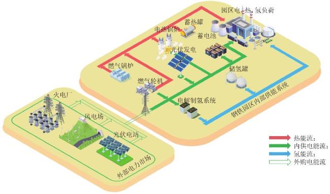
钢铁园区综合能源系统包括电、热、氢 3 种类型的能量需求  [13] ,系统结构如图1所示。钢铁厂能量需求由园区内部综合能源系统与电力市场交易电量满足。园区内部安装了光伏发电板(photovoltaic,PV)以供应电量,园区内部的能量转换设备包括:燃气轮机热电联产机组(gas turbine,GT)、制氢电解槽(electrolyzer,EL)、燃气锅炉(gas boiler,GB)与电热锅炉(electric boiler,EB)。除此以外,园区内设置储能系统以灵活调控时空能量功率,包括电储能(battery energy storage system,BESS)、热储能(thermal storage system,TSS)与氢储能(hydrogen storage system,HSS)。同时,钢铁厂与外部 3 类电厂:火电厂(thermal power plant,TPP)、风电场(wind power plant,WPP)与光伏电站(photovoltaic power plant,PVPP)签订长期交易合同,以确保钢铁厂具备稳定可靠的能量输入。钢铁园区中存在电、热、氢 3 类能量流。其中 GT 与 GB 将外购天然气转换为电热能;EB 实现园区内电能到热能的转换;EL 将电能转换为钢铁厂生产所需氢能;储能设备则灵活调控保证能量平衡  [14] 。需要说明的是,本文未进一步考虑氢能通过燃料电池实现热电联供,其原因主要是:本文在能量-碳流建模中对氢能赋予了明确的碳排放属性,从碳减排效果与系统经济性角度看,燃料电池在现阶段相较于园区既有电源形式并不具备显著优势,因此未将其纳入建模范围。
图1 钢铁园区系统结构

Fig. 1 Steel industrial park system architecture

GT 的功率及其约束为
$\begin{array}{c}\left\{\begin{array}{l}{\mathit{P}}_{\mathit{t}}^{\mathrm{G}\mathrm{T}}={\mathit{\eta }}_{\mathrm{G}\mathrm{T}}^{\mathrm{e}}{\mathit{G}}_{\mathit{t}}^{\mathrm{G}\mathrm{T}}\\ {\mathit{Q}}_{\mathit{t}}^{\mathrm{G}\mathrm{T}}={\mathit{\eta }}_{\mathrm{G}\mathrm{T}}^{\mathrm{h}\mathrm{t}}{\mathit{G}}_{\mathit{t}}^{\mathrm{G}\mathrm{T}}\\ {\mathit{P}}_{\mathrm{G}\mathrm{T}}^{\mathrm{m}\mathrm{i}\mathrm{n}}⩽{\mathit{P}}_{\mathit{t}}^{\mathrm{G}\mathrm{T}}⩽{\mathit{P}}_{\mathrm{G}\mathrm{T}}^{\mathrm{m}\mathrm{a}\mathrm{x}}\\ {\mathit{Q}}_{\mathrm{G}\mathrm{T}}^{\mathrm{m}\mathrm{i}\mathrm{n}}⩽{\mathit{Q}}_{\mathit{t}}^{\mathrm{G}\mathrm{T}}⩽{\mathit{Q}}_{\mathrm{G}\mathrm{T}}^{\mathrm{m}\mathrm{a}\mathrm{x}}\end{array}\right.\end{array}$
式中: ${\mathit{P}}_{\mathit{t}}^{\mathrm{G}\mathrm{T}}\mathrm{、}{\mathit{Q}}_{\mathit{t}}^{\mathrm{G}\mathrm{T}}$ 分别为 GT 在 t 时刻输出的电、热功率; ${\mathit{\eta }}_{\mathrm{G}\mathrm{T}}^{\mathrm{e}}\mathrm{、}{\mathit{\eta }}_{\mathrm{G}\mathrm{T}}^{\mathrm{h}\mathrm{t}}$ 为 GT 的电、热效率; ${\mathit{G}}_{\mathit{t}}^{\mathrm{G}\mathrm{T}}$t 时刻 GT 耗气功率; ${\mathit{P}}_{\mathrm{G}\mathrm{T}}^{\text{max}\text{ }}\mathrm{、}{\mathit{P}}_{\mathrm{G}\mathrm{T}}^{\text{min}\text{ }},\text{ }{\mathit{Q}}_{\mathrm{G}\mathrm{T}}^{\text{max}\text{ }}\mathrm{、}{\mathit{Q}}_{\mathrm{G}\mathrm{T}}^{\text{min}\text{ }}$ 分别为 GT 产电、热功率的上、下限。
EL 的功率及其约束为
$\begin{array}{c}\left\{\begin{array}{l}{\mathit{G}}_{\mathit{t}}^{\mathrm{E}\mathrm{L}}={\mathit{\eta }}_{\mathrm{E}\mathrm{L}}{\mathit{P}}_{\mathit{t}}^{\mathrm{E}\mathrm{L}}\\ {\mathit{G}}_{\mathrm{E}\mathrm{L}}^{\mathrm{m}\mathrm{i}\mathrm{n}}⩽{\mathit{G}}_{\mathit{t}}^{\mathrm{E}\mathrm{L}}⩽{\mathit{G}}_{\mathrm{E}\mathrm{L}}^{\mathrm{m}\mathrm{a}\mathrm{x}}\end{array}\right.\end{array}$
式中: ${\mathit{G}}_{\mathit{t}}^{\mathrm{E}\mathrm{L}}$ 为 EL t 时刻产生氢气的功率;ηEL 为EL 的电氢转换系数; ${\mathit{P}}_{\mathit{t}}^{\mathrm{E}\mathrm{L}}$ 为 EL 在 t 时刻消耗的电功率; ${\mathit{G}}_{\mathrm{E}\mathrm{L}}^{\mathit{m}\mathit{a}\mathit{x}}\mathrm{、}{\mathit{G}}_{\mathrm{E}\mathrm{L}}^{\mathit{m}\mathit{i}\mathit{n}}$ 分别为 EL 产氢功率的上、下限。
EB 的功率及其约束为
$\begin{array}{c}\left\{\begin{array}{l}{\mathit{Q}}_{\mathit{t}}^{\mathrm{E}\mathrm{B}}={\mathit{\eta }}_{\mathrm{E}\mathrm{B}}^{\mathrm{h}\mathrm{t}}{\mathit{P}}_{\mathit{t}}^{\mathrm{E}\mathrm{B}}\\ {\mathit{Q}}_{\mathrm{E}\mathrm{B}}^{\mathrm{m}\mathrm{i}\mathrm{n}}⩽{\mathit{Q}}_{\mathit{t}}^{\mathrm{E}\mathrm{B}}⩽{\mathit{Q}}_{\mathrm{E}\mathrm{B}}^{\mathrm{m}\mathrm{a}\mathrm{x}}\end{array}\right.\end{array}$
式中: ${\mathit{Q}}_{\mathit{t}}^{\mathrm{E}\mathrm{B}}$t 时刻 EB 输出的热功率; ${\mathit{\eta }}_{\mathrm{E}\mathrm{B}}^{\mathrm{h}\mathrm{t}}$ 为 GB电转热效率系数; ${\mathit{P}}_{\mathit{t}}^{\mathrm{E}\mathrm{B}}$t 时刻 EB 的耗电功率; ${\mathit{Q}}_{\mathrm{E}\mathrm{B}}^{\text{max}\text{ }}\mathrm{、}{\mathit{Q}}_{\mathrm{E}\mathrm{B}}^{\text{min}\text{ }}$ 分别为 EB 产热功率的上、下限。
GB 的功率及其约束为
$\begin{array}{c}\left\{\begin{array}{l}{\mathit{Q}}_{\mathit{t}}^{\mathrm{G}\mathrm{B}}={\mathit{\eta }}_{\mathrm{G}\mathrm{B}}^{\mathrm{h}\mathrm{t}}{\mathit{G}}_{\mathit{t}}^{\mathrm{G}\mathrm{B}}\\ {\mathit{Q}}_{\mathrm{G}\mathrm{B}}^{\mathrm{m}\mathrm{i}\mathrm{n}}⩽{\mathit{Q}}_{\mathit{t}}^{\mathrm{G}\mathrm{B}}⩽{\mathit{Q}}_{\mathrm{G}\mathrm{B}}^{\mathrm{m}\mathrm{a}\mathrm{x}}\end{array}\right.\end{array}$
式中: ${\mathit{Q}}_{\mathit{t}}^{\mathrm{G}\mathrm{B}}$t 时刻 GB 输出的热功率; ${\mathit{\eta }}_{\mathrm{G}\mathrm{B}}^{\mathrm{h}\mathrm{t}}$ 为GB 的供热效率; ${\mathit{G}}_{\mathit{t}}^{\mathrm{G}\mathrm{B}}$t 时刻 GB 的耗气功率; ${\mathit{Q}}_{\mathrm{G}\mathrm{B}}^{\text{max}\text{ }}\mathrm{、}{\mathit{Q}}_{\mathrm{G}\mathrm{B}}^{\text{min}\text{ }}$ 分别为 GB 输出热功率的上、下限。
BESS 功率及其约束为
$\left\{\begin{array}{c}{\mathit{P}}_{\mathit{t}}^{\mathrm{B}\mathrm{E}\mathrm{S}\mathrm{S}}={\mathit{P}}_{\mathit{t}-1}^{\mathrm{B}\mathrm{E}\mathrm{S}\mathrm{S}}+{\mathit{\eta }}_{\mathrm{B}\mathrm{E}\mathrm{S}\mathrm{S}}^{\mathrm{c}\mathrm{h}}{\mathit{R}}_{\mathit{t}-1}^{\mathrm{B}\mathrm{E}\mathrm{S}\mathrm{S},\mathrm{c}\mathrm{h}}+{\mathit{P}}_{\mathit{t}-1}^{\mathrm{B}\mathrm{E}\mathrm{S}\mathrm{S},\mathrm{c}\mathrm{h}}-\\ {\mathit{R}}_{\mathit{t}-1}^{\mathrm{B}\mathrm{E}\mathrm{S}\mathrm{S},\mathrm{d}\mathrm{i}\mathrm{s}}{\mathit{P}}_{\mathit{t}-1}^{\mathrm{B}\mathrm{E}\mathrm{S}\mathrm{S},\mathrm{c}\mathrm{h}}+{\mathit{\eta }}_{\mathrm{B}\mathrm{E}\mathrm{S}\mathrm{S}}^{\mathrm{d}\mathrm{i}\mathrm{s}}\\ {\mathit{P}}_{\mathrm{B}\mathrm{E}\mathrm{S}\mathrm{S},\mathrm{c}\mathrm{h}}^{\mathrm{m}\mathrm{i}\mathrm{n}}⩽{\mathit{P}}_{\mathit{t}}^{\mathrm{B}\mathrm{E}\mathrm{S}\mathrm{S},\mathrm{c}\mathrm{h}}⩽{\mathit{P}}_{\mathrm{B}\mathrm{E}\mathrm{S}\mathrm{S},\mathrm{c}\mathrm{h}}^{\mathrm{m}\mathrm{a}\mathrm{x}}\\ {\mathit{P}}_{\mathrm{B}\mathrm{E}\mathrm{S}\mathrm{S},\mathrm{d}\mathrm{i}\mathrm{s}}^{\mathrm{m}\mathrm{i}\mathrm{n}}⩽{\mathit{P}}_{\mathit{t}}^{\mathrm{B}\mathrm{E}\mathrm{S}\mathrm{S},\mathrm{c}\mathrm{h}}⩽{\mathit{P}}_{\mathrm{B}\mathrm{E}\mathrm{S}\mathrm{S},\mathrm{d}\mathrm{i}\mathrm{s}}^{\mathrm{m}\mathrm{a}\mathrm{x}}\\ {\mathit{P}}_{\mathrm{B}\mathrm{E}\mathrm{S}\mathrm{S}}^{\mathrm{m}\mathrm{i}\mathrm{n}}⩽{\mathit{P}}_{\mathit{t}}^{\mathrm{B}\mathrm{E}\mathrm{S}\mathrm{S},\mathrm{c}\mathrm{h}}⩽{\mathit{P}}_{\mathrm{B}\mathrm{E}\mathrm{S}\mathrm{S}}^{\mathrm{m}\mathrm{a}\mathrm{x}}\\ \mathit{ }\sum _{\mathit{t}}  {\mathit{P}}_{\mathit{t}}^{\mathrm{B}\mathrm{E}\mathrm{S}\mathrm{S},\mathrm{c}\mathrm{h}}=\sum _{\mathit{t}}  {\mathit{P}}_{\mathit{t}}^{\mathrm{B}\mathrm{E}\mathrm{S}\mathrm{S},\mathrm{d}\mathrm{i}\mathrm{s}}\\ {\mathit{P}}_{0}^{\mathrm{B}\mathrm{E}\mathrm{S}\mathrm{S}}={\mathit{P}}_{23}^{\mathrm{B}\mathrm{E}\mathrm{S}\mathrm{S}}=1/2{\mathit{P}}_{\mathrm{B}\mathrm{E}\mathrm{S}\mathrm{S}}^{\mathrm{m}\mathrm{a}\mathrm{x}}\end{array}\right.$
式中: ${\mathit{P}}_{\mathit{t}}^{\text{BESS}\text{ }}$ 为 BESS 在 t 时刻的运行功率; ${\mathit{\eta }}_{\text{BESS}\text{ }}^{\mathrm{c}\mathrm{h}}$ ${\mathit{\eta }}_{\mathrm{B}\mathrm{E}\mathrm{S}\mathrm{S}}^{\mathrm{d}\mathrm{i}\mathrm{s}}$ 分别为 BESS 的充、放电效率; ${\mathit{R}}_{\mathit{t}-1}^{\mathrm{B}\mathrm{E}\mathrm{S}\mathrm{S},\mathrm{c}\mathrm{h}}$ ${\mathit{R}}_{\mathit{t}-1}^{\mathrm{B}\mathrm{E}\mathrm{S}\mathrm{S}\text{ ,}\text{dis}\text{  }\text{分别为}\text{ }\mathit{t}-1\text{ }\text{时刻}\text{ BESS }\text{的充、放电状态}\text{;}}$ ${\mathit{P}}_{\mathit{t}-1}^{\mathrm{B}\mathrm{E}\mathrm{S}\mathrm{S},\mathrm{c}\mathrm{h}}\mathrm{、}{\mathit{P}}_{\mathit{t}-1}^{\mathrm{B}\mathrm{E}\mathrm{S}\mathrm{S},\mathrm{d}\mathrm{i}\mathrm{s}}$ 分别为 t-1 时刻 BESS 的充、放电功率; ${\mathit{P}}_{\text{BES}\text{,},\mathrm{c}\mathrm{h}}^{\text{max}\text{ }}\mathrm{、}{\mathit{P}}_{\text{BESS}\text{,}\text{ch}\text{ }}^{\text{min}\text{ }}$ 分别为 BESS 充电功率的上、下限; ${\mathit{P}}_{\text{BES}\text{, }\text{dis}\text{ }}^{\text{max}\text{ }}\mathrm{、}{\mathit{P}}_{\text{BESS}\text{,}\text{dis}\text{ }}^{\text{min}\text{ }}$ 分别为 BESS 放电功率的上、下限; ${\mathit{P}}_{\text{BESS}\text{ }}^{\text{max}\text{ }}\mathrm{、}{\mathit{P}}_{\text{BESS}\text{ }}^{\text{min}\text{ }}$ 分别为 BESS 的最大、小功率。
TSS 功率及其约束为
$\begin{array}{c}\left\{\begin{array}{l}{\mathit{Q}}_{\mathit{t}}^{\mathrm{T}\mathrm{S}\mathrm{S}}={\mathit{Q}}_{\mathit{t}-1}^{\mathrm{T}\mathrm{S}\mathrm{S}}+{\mathit{\eta }}_{\mathrm{T}\mathrm{S}\mathrm{S}}^{\mathrm{c}\mathrm{h}}{\mathit{R}}_{\mathit{t}-1}^{\mathrm{T}\mathrm{S}\mathrm{S},\mathrm{c}\mathrm{h}}+{\mathit{Q}}_{\mathit{t}-1}^{\mathrm{T}\mathrm{S}\mathrm{S},\mathrm{c}\mathrm{h}}-\\ \\ {\mathit{R}}_{\mathit{t}-1}^{\mathrm{T}\mathrm{S}\mathrm{S},\mathrm{d}\mathrm{i}\mathrm{s}}{\mathit{Q}}_{\mathit{t}-1}^{\mathrm{T}\mathrm{S}\mathrm{S},\mathrm{d}\mathrm{i}\mathrm{s}}/{\mathit{\eta }}_{\mathrm{T}\mathrm{S}\mathrm{S}}^{\mathrm{d}\mathrm{i}\mathrm{s}}\\ {\mathit{Q}}_{\mathrm{T}\mathrm{S}\mathrm{S},\mathrm{c}\mathrm{h}}^{\mathrm{m}\mathrm{i}\mathrm{n}}⩽{\mathit{Q}}_{\mathit{t}}^{\mathrm{T}\mathrm{S}\mathrm{S},\mathrm{c}\mathrm{h}}⩽{\mathit{Q}}_{\mathrm{T}\mathrm{S}\mathrm{S},\mathrm{c}\mathrm{h}}^{\mathrm{m}\mathrm{a}\mathrm{x}}\\ {\mathit{Q}}_{\mathrm{T}\mathrm{S}\mathrm{S},\mathrm{d}\mathrm{i}\mathrm{s}}^{\mathrm{m}\mathrm{i}\mathrm{n}}⩽{\mathit{Q}}_{\mathit{t}}^{\mathrm{T}\mathrm{S}\mathrm{S},\mathrm{d}\mathrm{i}\mathrm{s}}⩽{\mathit{Q}}_{\mathrm{T}\mathrm{S}\mathrm{S},\mathrm{d}\mathrm{i}\mathrm{s}}^{\mathrm{m}\mathrm{a}\mathrm{x}}\\ {\mathit{Q}}_{\mathrm{T}\mathrm{S}\mathrm{S}}^{\mathrm{m}\mathrm{i}\mathrm{n}}⩽{\mathit{Q}}_{\mathit{t}}^{\mathrm{T}\mathrm{S}\mathrm{S}}⩽{\mathit{Q}}_{\mathrm{T}\mathrm{S}\mathrm{S}}^{\mathrm{m}\mathrm{a}\mathrm{x}}\\ \sum _{\mathit{t}}  {\mathit{Q}}_{\mathit{t}}^{\mathrm{T}\mathrm{S}\mathrm{S},\mathrm{c}\mathrm{h}}=\sum _{\mathit{t}}  {\mathit{Q}}_{\mathit{t}}^{\mathrm{T}\mathrm{S}\mathrm{S},\mathrm{d}\mathrm{i}\mathrm{s}}\\ {\mathit{Q}}_{0}^{\mathrm{T}\mathrm{S}\mathrm{S}}={\mathit{Q}}_{23}^{\mathrm{T}\mathrm{S}\mathrm{S}}=1/2{\mathit{Q}}_{\mathrm{T}\mathrm{S}\mathrm{S}}^{\mathrm{m}\mathrm{a}\mathrm{x}}\end{array}\right.\end{array}$
式中: ${\mathit{Q}}_{\mathit{t}}^{\mathrm{T}\mathrm{S}\mathrm{S}}$ 为 TSS 在 t 时刻的蓄热功率; ${\mathit{\eta }}_{\mathrm{T}\mathrm{S}\mathrm{S}}^{\mathrm{c}\mathrm{h}}\mathrm{、}{\mathit{\eta }}_{\mathrm{T}\mathrm{S}\mathrm{S}}^{\mathrm{d}\mathrm{i}\mathrm{s}}$分别为 TSS 的充、放热效率; ${\mathit{R}}_{\mathit{t}-1}^{\mathrm{T}\mathrm{S}\mathrm{S},\mathrm{c}\mathrm{h}}\mathrm{、}{\mathit{R}}_{\mathit{t}-1}^{\mathrm{T}\mathrm{S}\mathrm{S},\mathrm{d}\mathrm{i}\mathrm{s}}$ 分别为 t-1 时刻 TSS 的充、放热状态; ${\mathit{Q}}_{\mathit{t}-1}^{\mathrm{T}\mathrm{S}\mathrm{S},\mathrm{c}\mathrm{h}}\mathrm{、}{\mathit{Q}}_{\mathit{t}-1}^{\mathrm{T}\mathrm{S}\mathrm{S},\text{ }\text{dis}\text{ }}$分别为 t-1 时刻 TSS 的充、放热功率; ${\mathit{Q}}_{\mathrm{T}\mathrm{S}\mathrm{S},\mathrm{c}\mathrm{h}}^{\text{max}\text{ }}$ ${\mathit{Q}}_{\mathrm{T}\mathrm{S}\mathrm{S},\mathrm{c}\mathrm{h}}^{\mathrm{m}\mathrm{i}\mathrm{n}}$ 分别为 TSS 蓄热功率的上、下限; ${\mathit{Q}}_{\mathrm{T}\mathrm{S}\mathrm{S},\mathrm{d}\mathrm{i}\mathrm{s}}^{\mathrm{m}\mathrm{a}\mathrm{x}}$ ${\mathit{Q}}_{\mathrm{T}\mathrm{S}\mathrm{S},\mathrm{d}\mathrm{i}\mathrm{s}}^{\mathrm{m}\mathrm{i}\mathrm{n}}$ 分别为 TSS 放热功率的上、下限; ${\mathit{Q}}_{\mathrm{T}\mathrm{S}\mathrm{S}}^{\mathrm{m}\mathrm{a}\mathrm{x}}$ ${\mathit{Q}}_{\mathrm{T}\mathrm{S}\mathrm{S}}^{\mathrm{m}\mathrm{i}\mathrm{n}}$ 分别为 TSS 蓄热功率的上、下限。
HSS 功率及其约束为
$\begin{array}{c}\left\{\begin{array}{l}{\mathit{G}}_{\mathit{t}}^{\mathrm{H}\mathrm{S}\mathrm{S}}={\mathit{G}}_{\mathit{t}-1}^{\mathrm{H}\mathrm{S}\mathrm{S}}+{\mathit{\eta }}_{\mathrm{H}\mathrm{S}\mathrm{S}}^{\mathrm{c}\mathrm{h}}{\mathit{R}}_{\mathit{t}-1}^{\mathrm{H}\mathrm{S}\mathrm{S},\mathrm{c}\mathrm{h}}{\mathit{G}}_{\mathit{t}-1}^{\mathrm{H}\mathrm{S}\mathrm{S},\mathrm{c}\mathrm{h}}-\\ \mathrm{ }{\mathit{R}}_{\mathit{t}-1}^{\mathrm{H}\mathrm{S}\mathrm{S},\mathrm{d}\mathrm{i}\mathrm{s}}{\mathit{G}}_{\mathit{t}-1}^{\mathrm{H}\mathrm{S}\mathrm{S},\mathrm{d}\mathrm{i}\mathrm{s}}/{\mathit{\eta }}_{\mathrm{H}\mathrm{S}\mathrm{S}}^{\mathrm{d}\mathrm{i}\mathrm{s}}\\ {\mathit{G}}_{\mathrm{H}\mathrm{S}\mathrm{S},\mathrm{c}\mathrm{h}}^{\mathrm{m}\mathrm{i}\mathrm{n}}⩽{\mathit{G}}_{\mathit{t}}^{\mathrm{H}\mathrm{S}\mathrm{S},\mathrm{c}\mathrm{h}}⩽{\mathit{G}}_{\mathrm{H}\mathrm{S}\mathrm{S},\mathrm{c}\mathrm{h}}^{\mathrm{m}\mathrm{a}\mathrm{x}}\\ {\mathit{G}}_{\mathrm{H}\mathrm{S}\mathrm{S},\mathrm{d}\mathrm{i}\mathrm{s}}^{\mathrm{m}\mathrm{i}\mathrm{n}}⩽{\mathit{G}}_{\mathit{t}}^{\mathrm{H}\mathrm{S}\mathrm{S},\mathrm{d}\mathrm{i}\mathrm{s}}⩽{\mathit{G}}_{\mathrm{H}\mathrm{S}\mathrm{S},\mathrm{d}\mathrm{i}\mathrm{s}}^{\mathrm{m}\mathrm{a}\mathrm{x}}\\ {\mathit{G}}_{\mathrm{H}\mathrm{S}\mathrm{S}}^{\mathrm{m}\mathrm{i}\mathrm{n}}⩽{\mathit{G}}_{\mathit{t}}^{\mathrm{H}\mathrm{S}\mathrm{S}}⩽{\mathit{G}}_{\mathrm{H}\mathrm{S}\mathrm{S}}^{\mathrm{m}\mathrm{a}\mathrm{x}}\\ \sum _{\mathit{t}}  {\mathit{G}}_{\mathit{t}}^{\mathrm{H}\mathrm{S}\mathrm{S},\mathrm{c}\mathrm{h}}=\sum _{\mathit{t}}  {\mathit{G}}_{\mathit{t}}^{\mathrm{H}\mathrm{S}\mathrm{S},\mathrm{d}\mathrm{i}\mathrm{s}}\\ {\mathit{G}}_{0}^{\mathrm{H}\mathrm{S}\mathrm{S}}={\mathit{G}}_{23}^{\mathrm{H}\mathrm{S}\mathrm{S}}=1/2{\mathit{G}}_{\mathrm{H}\mathrm{S}\mathrm{S}}^{\mathrm{m}\mathrm{a}\mathrm{x}}\end{array}\right.\end{array}$
式中: ${\mathit{G}}_{\mathit{t}}^{\mathrm{H}\mathrm{S}\mathrm{S}}$ 为 HSS 在 t 时刻的储氢功率; ${\mathit{\eta }}_{\mathrm{H}\mathrm{S}\mathrm{S}}^{\mathrm{c}\mathrm{h}}$ ${\mathit{\eta }}_{\mathrm{H}\mathrm{S}\mathrm{S}}^{\mathrm{d}\mathrm{i}\mathrm{s}}$ 分别为 HSS 的充、放效率; ${\mathit{R}}_{\mathit{t}-1}^{\mathrm{H}\mathrm{S}\mathrm{S},\mathrm{c}\mathrm{h}\mathrm{、}}{\mathit{R}}_{\mathit{t}-1}^{\mathrm{H}\mathrm{S}\mathrm{S},\mathrm{d}\mathrm{i}\mathrm{s}}$分别为 t-1 时刻 HSS 的充、放状态; ${\mathit{G}}_{\mathit{t}-1}^{\mathrm{H}\mathrm{S}\mathrm{S},\mathrm{c}\mathrm{h}}$ ${\mathit{G}}_{\mathit{t}-1}^{\mathrm{H}\mathrm{S}\mathrm{S},\mathrm{d}\mathrm{i}\mathrm{s}}$ 分别为 t-1 时刻 HSS 的充、放功率; ${\mathit{G}}_{\mathrm{H}\mathrm{S}\mathrm{S},\mathrm{c}\mathrm{h}}^{\text{max}\text{ }}$ ${\mathit{G}}_{\text{HSS}\text{,}\text{ch}\text{ }}^{\text{min}\text{ }}$ 分别为 HSS 储氢功率的上、下限; ${\mathit{G}}_{\text{HSS}\text{,}\text{dis}\text{ }}^{\text{max}\text{ }}$ ${\mathit{G}}_{\mathrm{H}\mathrm{S}\mathrm{S},\text{ }\text{dis}\text{ }}^{\mathrm{m}\mathrm{i}\mathrm{n}}$ 分别为 HSS 放氢功率的上、下限; ${\mathit{G}}_{\mathrm{H}\mathrm{S}\mathrm{S}}^{\text{max}\text{ }}$ ${\mathit{G}}_{\text{HSS}\text{ }}^{\text{min}\text{ }}$ 分别为 HSS 储氢功率的上、下限。

2 电-热-氢分时碳排放因子建模

碳排放因子作为连接能量流与碳排放之间的核心中介变量,其建模精度与分时动态性直接影响多能系统碳责任的分摊与调度策略的低碳导向性。为实现钢铁园区多能系统的分时碳排放测算,本文提出一种基于能量-碳流的分时碳排放因子建模方法,以设备出力与电源结构为变量,建立电-热-氢 3 类碳排放因子的统一建模框架。

2.1 电-热-氢能量设备碳排放流模型

园区内的各个设备可以根据能量转换形式分为单输人-单输出设备以及单输入-多输出设备  [15] 。根据碳流守恒定律,设备输入端的碳流应等于输出端的碳流  [16] 。在能量转换中产生的损耗,并不影响总碳排放量。根据这个原则,某单输入-单输出设备 i 的碳流模型为
$\begin{array}{c}{\mathit{e}}_{\mathit{t}}^{\mathit{i},\text{ }\text{out}\text{ }}=\frac{{\mathit{e}}_{\mathit{t}}^{\mathit{i},\text{ }\text{in}\text{ }}}{{\mathit{\eta }}_{\mathit{i}}}\end{array}$
式中: ${\mathit{e}}_{\mathit{t}}^{\mathit{i},\text{ }\text{in}\text{ }}\mathrm{、}{\mathit{e}}_{\mathit{t}}^{\mathit{i},\text{ }\text{out}\text{ }}$ 分别为 t 时刻 i 设备输入端与输出端能量的碳排放因子;ηii 设备的能量转换效率。
对于某单输入-多输出设备 j ,输入端的碳流按照能量转换效率比例分配至电热能量输出端,其碳流模型为
$\begin{array}{c}\left\{\begin{array}{l}{\mathit{e}}_{\mathit{t}}^{\mathrm{e},\mathit{j}}=\frac{{\mathit{e}}_{\mathit{t}}^{\mathit{j},\mathrm{i}\mathrm{n}}}{2{\mathit{\eta }}_{\mathit{j}}^{\mathrm{e}}}\\ {\mathit{e}}_{\mathit{t}}^{\mathrm{h}\mathrm{t},\mathit{j}}=\frac{{\mathit{e}}_{\mathit{t}}^{\mathit{j},\mathrm{i}\mathrm{n}}}{2{\mathit{\eta }}_{\mathit{j}}^{\mathrm{h}\mathrm{t}}}\end{array}\right.\end{array}$
式中: ${\mathit{e}}_{\mathit{t}}^{\mathrm{e},\mathit{j}}\mathrm{、}{\mathit{e}}_{\mathit{t}}^{\mathrm{h}\mathrm{t},\mathit{j}}$ 分别为 t 时刻 j 设备输出端发电侧与制热侧的碳排放因子; ${\mathit{\eta }}_{\mathit{j}}^{\mathrm{e}}\mathrm{、}{\mathit{\eta }}_{\mathit{j}}^{\mathrm{h}}$ 分别为 j 设备的电、热转换效率。
GT t 时刻的碳排放为
$\begin{array}{c}\left\{\begin{array}{l}{\mathit{E}}_{\mathit{t}}^{\mathrm{e},\mathrm{G}\mathrm{T}}={\mathit{e}}_{\mathit{t}}^{\mathrm{e},\mathrm{G}\mathrm{T}}{\mathit{P}}_{\mathit{t}}^{\mathrm{G}\mathrm{T}}=\frac{{\mathit{e}}_{\mathit{t}}^{\mathrm{G}\mathrm{T},\mathrm{i}\mathrm{n}}}{2{\mathit{\eta }}_{\mathrm{G}\mathrm{T}}^{\mathrm{e}}}{\mathit{G}}_{\mathit{t}}^{\mathrm{G}\mathrm{T}}\\ {\mathit{E}}_{\mathit{t}}^{\mathrm{h}\mathrm{t},\mathrm{G}\mathrm{T}}={\mathit{e}}_{\mathit{t}}^{\mathrm{h}\mathrm{t},\mathrm{G}\mathrm{T}}{\mathit{Q}}_{\mathit{t}}^{\mathrm{G}\mathrm{T}}=\frac{{\mathit{e}}_{\mathit{t}}^{\mathrm{G}\mathrm{T},\mathrm{i}\mathrm{n}}}{2{\mathit{\eta }}_{\mathrm{G}\mathrm{T}}^{\mathrm{h}\mathrm{t}}}{\mathit{G}}_{\mathit{t}}^{\mathrm{G}\mathrm{T}}\end{array}\right.\end{array}$
式中: ${\mathit{E}}_{\mathit{t}}^{\mathrm{e},\mathrm{G}\mathrm{T}}\mathrm{、}{\mathit{E}}_{\mathit{t}}^{\mathrm{h}\mathrm{t},\mathrm{G}\mathrm{T}}$ 分别为 t 时刻 GT 的电能与热能碳排放量; ${\mathit{e}}_{\mathit{t}}^{\mathrm{e},\mathrm{G}\mathrm{T}}\mathrm{、}{\mathit{e}}_{\mathit{t}}^{\mathrm{h}\mathrm{t},\mathrm{G}\mathrm{T}}$ 分别为 t 时刻 GT 的电能与热能碳排放因子; ${\mathit{e}}_{\mathit{t}}^{\mathrm{G}\mathrm{T},\mathrm{i}\mathrm{n}}$ 为 GT 输入端能量的碳排放因子。

2.2 电-热-氢分时碳排放因子建模

本文方法基于碳流守恒原则与能量分摊机制,构建多能系统碳排放因子的分时映射关系。碳排放因子定义为单位终端能量所承载的碳排放量,随系统设备运行状态、能量路径与购电结构在时间维度上分时演化。建模主要包括3步:1)源头碳排放识别。明确各类一次能源所对应的碳排放强度,火电购电、天然气均具备不同的碳排放因子;2)能量-碳流路径分摊。将一次能源通过能量转换设备转化为终端能量(热/氢),根据能量效率与转换流向,按比例分摊碳排放;3)分时碳排放因子生成。将各终端在各时刻的某种能量输出所携带的碳排放量除以该时刻园区总消耗能量,各自生成电-热-氢的分时碳排放因子。
分时电能碳排放因子的关键影响因素包括园区内部产电结构(GT、PV)与外部购电电源(TPP、WPP、PVPP)构成。以碳源溯源为原则  [17-19] ,园区当期所有用电需求的碳排放来源可拆分为内部设备供电的碳排放与外部交易电量的碳排放。分时电能碳排放因子为
$\begin{array}{c}{\mathit{e}}_{\mathit{t}}^{\mathrm{e}}=\frac{{\mathit{E}}_{\mathit{t}}^{\mathrm{e},\mathrm{G}\mathrm{T}}+{\mathit{E}}_{\mathit{t}}^{\mathrm{f}}}{{\mathit{P}}_{\mathit{t}}^{\text{load}\text{ }}+{\mathit{P}}_{\mathit{t}}^{\mathrm{E}\mathrm{B}}+{\mathit{P}}_{\mathit{t}}^{\mathrm{E}\mathrm{L}}}\end{array}$
式中: ${\mathit{e}}_{\mathit{t}}^{\mathrm{e}}$ 为分时电能设备碳排放因子; ${\mathit{E}}_{\mathit{t}}^{\mathrm{f}}$ 为 TPP的碳排放量; ${\mathit{P}}_{\mathit{t}}^{\text{load}\text{ }}$t 时刻钢铁园区的用户电负荷。
热能碳排放因子的核心在于不同热源的碳排差异。园区主要热源包括 GB、GT 产热以及 EB等。按照能量流-碳流映射关系,热碳排可拆解为:气源供热(GB、GT 产热)碳排与电源供热(EB)间接碳排。分时热能碳排放因子为
$\begin{array}{c}{\mathit{e}}_{\mathit{t}}^{\mathrm{h}\mathrm{t}}=\frac{{\mathit{E}}_{\mathit{t}}^{\mathrm{h}\mathrm{t},\mathrm{G}\mathrm{T}}+{\mathit{E}}_{\mathit{t}}^{\mathrm{E}\mathrm{B}}+{\mathit{E}}_{\mathit{t}}^{\mathrm{G}\mathrm{B}}}{{\mathit{Q}}_{\text{load}\text{ }}}\end{array}$
式中: ${\mathit{e}}_{\mathit{t}}^{\mathrm{h}\mathrm{t}}$ 为分时热能设备碳排放因子; ${\mathit{E}}_{\mathit{t}}^{\mathrm{E}\mathrm{B}}$ 为EB 的碳排放量; ${\mathit{E}}_{\mathit{t}}^{\mathrm{G}\mathrm{B}}$ 为 GB 的碳排放量;Qload t时刻钢铁园区内的用户热负荷。
气源供热部分根据天然气燃烧碳排放因子、热效率反推碳排放。电源供热部分则根据 EB 效率与每时刻输入锅炉的电能效率进行折算。
氢能碳排放主要取决于制氢用电的碳属性,园区以电解水为主要制氢路径,其碳排放来自输入电能的各时刻碳排放因子。因此,氢能碳排放因子可等价表示为制氢时刻的电能碳排放因子与设备效率耦合结果。氢能碳排放因子为
$\begin{array}{c}{\mathit{e}}_{\mathit{t}}^{\mathrm{h}}=\frac{{\mathit{E}}_{\mathit{t}}^{\mathrm{E}\mathrm{L}}}{{\mathit{G}}_{\mathit{t}}^{\text{load}\text{ }}}\end{array}$
式中: ${\mathit{e}}_{\mathit{t}}^{\mathrm{h}}$t 时刻分时氢能设备碳排放因子; ${\mathit{E}}_{\mathit{t}}^{\mathrm{E}\mathrm{L}}$ 为 EL 的碳排放量; ${\mathit{G}}_{\mathit{t}}^{\mathrm{l}\mathrm{o}\mathrm{a}\mathrm{d}}$t 时刻钢铁园区内用户氢负荷。

2.3 电-热-氢分时碳排放因子建模

储能设备对碳排放因子的影响体现为碳时移机制。从碳流的角度分析,当某种能量的储能设备充能时,相当于吸收了该能量类型的一部分碳排放,造成该时段碳排放的下降;相应的,当储能设备放能时,将其视作产能设备,向外释放碳排放  [20] 。进一步地,在储能设备的充能阶段,输入的能流—碳流是明确的,可区分每一单位输入能量的碳属性。然而,能量一旦进入储能设备内部,来自不同时段、不同来源的能量碳属性混合在一起,其内部能量不再能够区分碳标签。此时,储能设备的碳排放归属不再可追踪。因此,在放电阶段,需将储能设备中已混合的碳排放按当前单位能量均摊释放。
以电储能为例,园区内电储能分时碳排放因子为
$\begin{array}{rrr}{\mathit{e}}_{\mathit{t}}^{\mathrm{B}\mathrm{E}\mathrm{S}\mathrm{S}}=\frac{1}{{\mathit{P}}_{\mathit{t}}^{\mathrm{B}\mathrm{E}\mathrm{S}\mathrm{S}}}\left({\mathit{e}}_{\mathit{t}-1}^{\mathrm{B}\mathrm{E}\mathrm{S}\mathrm{S}}{\mathit{P}}_{\mathit{t}-1}^{\mathrm{B}\mathrm{E}\mathrm{S}\mathrm{S}}+{\mathit{e}}_{\mathit{t}}^{\mathrm{e}}{\mathit{P}}_{\mathit{t}}^{\mathrm{B}\mathrm{E}\mathrm{S}\mathrm{S},\mathrm{c}\mathrm{h}}\mathrm{\Delta }\mathit{t}\right)-\frac{1}{{\mathit{P}}_{\mathit{t}}^{\mathrm{B}\mathrm{E}\mathrm{S}\mathrm{S}}}{\mathit{e}}_{\mathit{t}-1}^{\mathrm{B}\mathrm{E}\mathrm{S}\mathrm{S}}{\mathit{P}}_{\mathit{t}}^{\mathrm{B}\mathrm{E}\mathrm{S}\mathrm{S},\mathrm{d}\mathrm{i}\mathrm{s}}\mathrm{\Delta }\mathit{t}&\end{array}$
式中: ${\mathit{e}}_{\mathit{t}}^{\text{BESS}\text{ }}$t 时刻电储能分时碳排放因子;Δt为时间间隔,本文取 1 h。
园区内电-热-氢 3 类能量系统的碳流根据每时刻能量转换设备的出力以及储能设备的充放状态发生分时变化,因此可由能量流-碳流映射关系追踪 3 类能量的总体碳排放因子,具体可以参考文献[12]。例如,电能分时碳排放因子为
$\begin{array}{c}{\mathit{e}}_{\mathit{t}}^{\mathrm{E}}=\frac{{\mathit{E}}_{\mathit{t}}^{\mathrm{e}}+{\mathit{E}}_{\mathit{t}}^{\mathrm{B}\mathrm{E}\mathrm{S}\mathrm{S}}}{{\mathit{P}}_{\mathit{t}}^{\mathrm{l}\mathrm{o}\mathrm{a}\mathrm{d}}+{\mathit{P}}_{\mathit{t}}^{\mathrm{E}\mathrm{B}}+{\mathit{P}}_{\mathit{t}}^{\mathrm{E}\mathrm{L}}+{\mathit{P}}_{\mathit{t}}^{\mathrm{B}\mathrm{E}\mathrm{S}\mathrm{S}}}\end{array}$
式中: ${\mathit{e}}_{\mathit{t}}^{\mathrm{E}}$ 为含储能设备的园区电能分时碳排放因子; ${\mathit{E}}_{\mathit{t}}^{\mathrm{e}}\mathrm{、}{\mathit{E}}_{\mathit{t}}^{\text{BESS}\text{ }}$ 分别为电能设备与电储能设备 t 时刻的碳排放量。

3 钢铁园区源-荷协同低碳经济调度模型

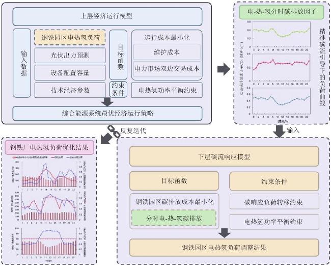
本文构建钢铁园区源-荷协同经济调度与低碳响应模型,如图2所示。上层经济运行模型以钢铁园区运行经济性最优为目标,考虑园区内产能设备运行经济性与电力市场双边交易成本。下层碳流响应模型以碳排放最小为目标,利用电-热-氢分时碳排放因子引导用户改变用能行为,并将响应后的电-热-氢 3 种负荷曲线传递回上层。收玫条件为:比较上下两次迭代的目标函数变化量,当所述变化量小于预设阈值或迭代次数达到预设值时,停止迭代。通过上下层的不断迭代,最终达到运行经济性与减少碳排放的协同目标。

3.1 钢铁生产流程的需求响应潜力

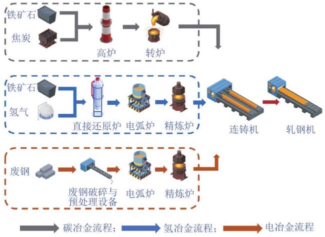
钢铁生产有 3 类典型工艺流程:碳冶金、氢冶金与电冶金,如图3所示。碳冶金以铁矿石和焦炭为主要原料,经高炉完成铁矿石的碳基还原,产出的铁水进入转炉进一步脱碳炼钢,随后通过连铸机铸坯并经轧钢机轧制成材,该流程是当前占比最高的传统路线。氢冶金则以氢气替代焦炭作为还原剂,铁矿石在直接还原炉中生成海绵铁,再送入电弧炉与部分废钢一同熔炼成钢水,经精炼炉净化后进入连铸和轧钢环节。电冶金以废钢为主要原料,经破碎与预处理后直接送入电弧炉熔化,钢水经精炼、连铸与轧制形成成材。相比于碳冶金流程,氢冶金与电冶金具备能耗电力化、可调节性强的特点。
在氢冶金流程中,铁矿石经氢气直接还原后进入电弧炉冶炼。电弧炉作为铁合金最重要的冶炼设备,国内目前主流是以每炉次为单位进行生产。电弧炉炼钢环节属于典型高耗能间歇性工序,单炉冶炼周期一般为 1∼2 h 。通过调整电弧炉开炉时间、冶炼功率水平以及投料批次,能够在不影响冶炼产量的前提下实现灵活移峰。在实际生产中,须控制冶炼过程中用电负荷不变,炉次之间的时间间隔可由当日生产计划进行调整。因此,电弧炉环节是钢铁生产中电力需求响应潜力的主要来源。而其余主要生产设备可在工艺允许的范围内通过生产调度优化的方式,获得一定的需求响应空间。与此同时,直接还原工序对氢气用量的需求并非完全刚性。不同批次铁矿石的装入节奏与还原反应速率可以根据生产组织进行优化,从而实现氢气消耗的时序分布调整。直接还原炉在短期内具备一定的运行弹性,可通过控制还原温度、气体流量及停留时间来改变瞬时氢耗水平,使氢气的消耗曲线在时间上呈现可移动、可平移的特征。总体而言,钢铁生产存在总能耗相对刚性、用能时序可调节的特征。本文通过调整生产时间,设置可转移负荷,总能耗不变,兼顾生产连续性与调度灵活性  [21-22]
图2 源—荷协同经济调度与低碳响应机制框架

Fig. 2 Source-load collaborative economic dispatch and low-carbon response mechanism framework

图3 钢铁生产的3种典型工艺流程

Fig. 3 Three typical steelmaking process routes

3.2 上层运行经济性模型

上层经济调度模型的优化目标为园区产能设备运行经济性最优,目标函数主要包括设备维护成本与能源购买成本,即
$\begin{array}{c}{\mathit{C}}_{\mathrm{s}\mathrm{y}\mathrm{s}}=\mathit{m}\mathit{i}\mathit{n}\left({\mathit{C}}_{\mathrm{m}}+{\mathit{C}}_{\mathrm{f}}+{\mathit{C}}_{\mathrm{c}\mathrm{d}}\right)\end{array}$
式中:Csys  为系统运行成本;CmCfCcd 分别为设备维护成本、购能成本与储能装置充放寿命损耗成本。
购能成本为
$\begin{array}{rrr}{\mathit{C}}_{\mathrm{f}}=\mathit{ }\sum _{\mathit{t}}  \left[{\mathit{\alpha }}_{\mathrm{G}}\left({\mathit{G}}_{\mathit{t}}^{\mathrm{G}\mathrm{T}}+{\mathit{G}}_{\mathit{t}}^{\mathrm{G}\mathrm{B}}\right)+{\mathit{\alpha }}_{\mathrm{T}\mathrm{P}\mathrm{P}}{\mathit{P}}_{\mathit{t}}^{\mathrm{T}\mathrm{P}\mathrm{P}}+\right. \left.{\mathit{\alpha }}_{\mathrm{P}\mathrm{V}\mathrm{P}\mathrm{P}}{\mathit{P}}_{\mathit{t}}^{\mathrm{P}\mathrm{V}\mathrm{P}\mathrm{P}}+{\mathit{\alpha }}_{\mathrm{W}\mathrm{P}\mathrm{P}}{\mathit{P}}_{\mathit{t}}^{\mathrm{W}\mathrm{P}\mathrm{P}}\right]&\end{array}$
式中:αG 为钢铁园区从上级气网购买天然气的费用;αTPP αPVPP αWPP  分别为钢铁园区与 TPP、 PVPP、 WPP 签订的单位电力交易价格; ${\mathit{P}}_{\mathit{t}}^{\mathrm{T}\mathrm{P}\mathrm{P}}\mathrm{、}{\mathit{P}}_{\mathit{t}}^{\mathrm{P}\mathrm{V}\mathrm{P}\mathrm{P}}$ ${\mathit{P}}_{\mathit{t}}^{\mathrm{W}\mathrm{P}\mathrm{P}}$ 分别为钢铁园区 t 时刻从 TPP、PVPP、WPP的购电功率。
储能装置充、放电寿命损耗成本可参考文献[23]。钢铁园区内存在电、热、氢 3 种形式的需求平衡约束。为了刻画多能系统中能量流向对碳排放因子的影响,在建模过程中对系统能量流向进行细化建模,对各类电源设备的出力进行路径划分  [24] 。引入按终端负荷类型划分的出力决策变量。具体而言,每一类电源均被拆分为流向电负荷、电热设备与电解制氢系统 3 类路径的出力变量,从而形成"源—终端"的能量映射关系,具体满足系统电能平衡约束、系统总体电-热-氢能量平衡约束。

3.3 下层碳流响应模型

下层碳排放调整模型的优化目标为钢铁厂用能碳排放成本最小  [24] 。总优化目标为
$\begin{array}{c}{\mathit{C}}_{\text{total}\text{ }}=\mathit{m}\mathit{i}\mathit{n}\left[{\mathit{c}}_{\text{carbon}\text{ }}\left({\mathit{C}}_{\mathrm{e}}+{\mathit{C}}_{\mathrm{h}\mathrm{t}}+{\mathit{C}}_{\mathrm{h}}\right)\right]\end{array}$
式中:ccarbon  为碳价;CeChtCh 分别为钢铁厂的用电、热、氢碳排放量。
由于目标函数碳成本的加入,钢铁企业的多能负荷根据碳流的时间分布做出响应调整,由高碳强度时域转移至低碳强度时域,而钢铁企业电热氢负荷总量不变,则满足负荷转移平衡约束,可参考文献[2526]。

4 算例分析

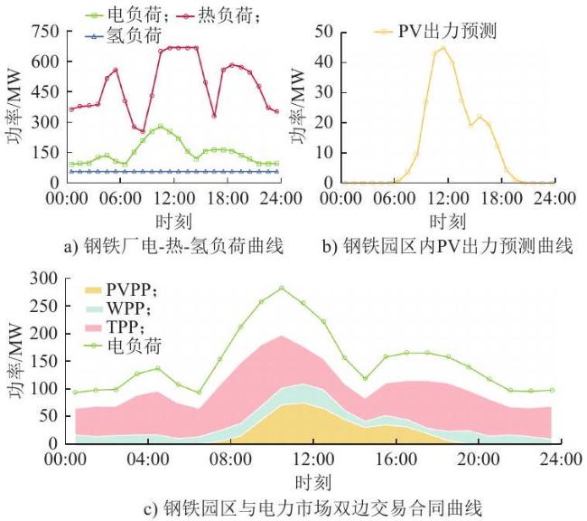
本文以典型钢铁厂为算例。该钢铁厂内部存在电、热、氢 3 种类型的负荷,钢铁园区内部配置光伏板。此外,考虑到用电稳定性要求,园区大部分的电力需求由电力市场双边交易满足  [27-31] 。3 种类型负荷、光伏预测出力、交易合同的功率曲线如图4所示。

4.1 电—热—氢分时碳排放因子特性分析

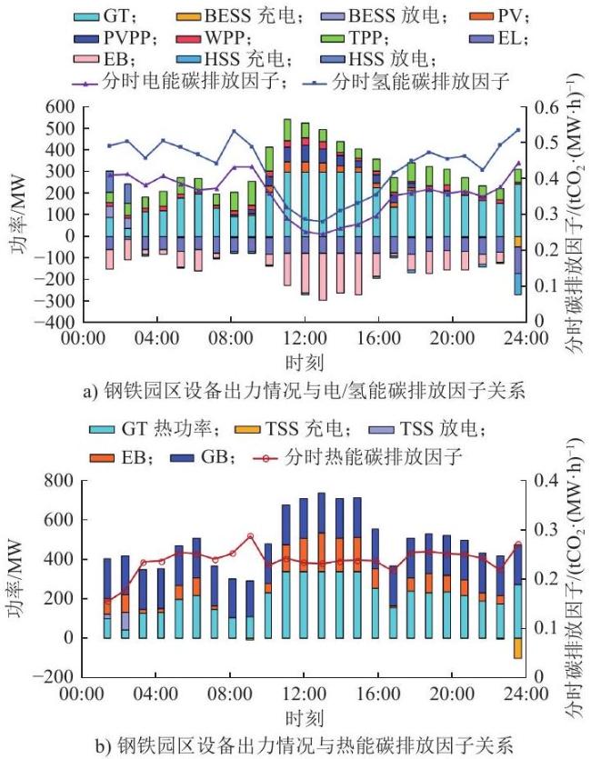
为探究分时碳排放因子的形成机制与其对系统调度行为的引导作用,本文从电-热-氢 3 类能量的角度分别分析了单位能量碳排放因子的时间演化特征及其与系统碳排放来源的内在关系,相关结果如图5 所示。由图5可见,电能碳排放因子波动幅度大,在白天(08:00—16:00)显著下降,夜间(20:00 以后)逐步升高。这一趋势与园区 PV 出力变化高度一致。白天时段,园区 PV 出力较高,同时 WPP、PVPP 交易电量占比上升,系统整体用电碳强度下降,从而拉低单位电能碳排放因子。相反,在 PV、PVPP归零且外部 TPP比例上升的夜间时段,单位电能碳排放因子迅速抬升,呈现出明显的峰谷特征。
热能碳排放因子的变化相对平缓,主要原因在于热源结构稳定,以 GB 和 GT 产热为主,虽然 EB 存在一定调节空间,但整体上热源构成在调度周期内未发生显著改变,因而碳排放因子波动受限。氢能碳排放因子则呈现出阶段性波动特征,其变化趋势在一定程度上受到电能碳排放因子的驱动。
图4 钢铁厂相关功率曲线

Fig. 4 Power curves of steel plant

图5 钢铁园区设备出力情况与电/热/氢能碳排放因子关系

Fig. 5 Correlation between equipment output and carbon emission factors(electricity/heat/hydrogen)in steel industrial park

综合来看,火电是电/热/氢能碳排放因子的主要影响源,其出力在夜间占比上升,导致电-热-氢能碳排放因子在20:00后明显抬升。在白天可再生能源出力较高的时段,电-热-氢能碳排放因子显著下降。分时碳排放因子作为能流—碳流融合的重要中介变量,能够反映当前系统能量结构与碳排关系,也为负荷响应与调度优化提供了可量化的引导依据。

4.2 负荷响应行为分析

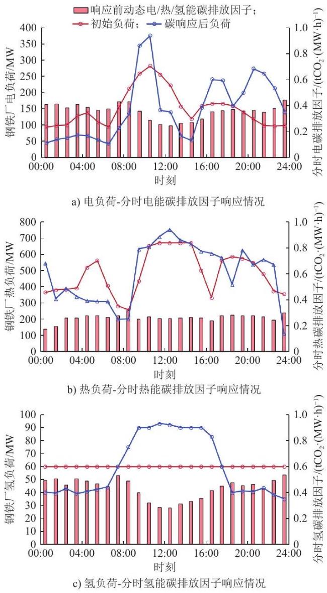
引入分时碳排放因子并构建负荷响应机制后,钢铁园区实现了明显的用能时序优化,钢铁园区负荷响应如图6所示。图6a)仿真结果显示,电负荷响应未严格追随碳排放因子最低值调整(12:00—13:00、17:00—18:00),主要原因是:系统优先调度设备,保障整体负荷需求满足。由于该时刻部分电负荷需要转化为热负荷,因此调低电负荷可能导致热能供应不足。
图6 钢铁园区负荷响应情况

Fig. 6 Load response characteristics of steel industrial park

对于热能-碳流的响应表现,图6b)显示,响应前热能碳排放因子在夜间(01:00—06:00)与中午(11:00—14:00)相对较高。响应后,热负荷显著从高碳时段(13:00 )转移到低碳排放因子时段(08:00、21:00)。由于钢铁园区的热负荷总量较高,对整体碳排放贡献占比大,碳优化模型优先保障其低碳调节策略,因此热负荷在碳排放因子变化驱动下响应最为显著。在负荷允许的灵活性范围内,热负荷较多地向低碳时段转移,从而降低热能碳排放因子均值,达到系统总体减碳目的。
对于氢能系统,图6c)显示,响应后氢负荷集中在 08:00—18:00 时段释放,避开高碳电力时期。氢负荷受制于 EL 运行周期和能量转换效率限制,响应空间较小。在有限的调节能力下,EL 尽量避开高碳电源输出时段制氢,选择在风光比例高、电能碳排放因子较低时运行。本文提出的碳响应机制下多能负荷的钢铁厂用能协同调整策略:1)热负荷作为碳排放的主要来源,响应优先级最高,系统为其让渡了部分电能调节空间;2)电负荷在保障热系统低碳目标下出现非最优调整行为,但整体趋势仍向低碳方向发展;3)氢系统因其灵活性有限,响应受限,但仍能实现一定的避峰填谷与碳趋避功能。

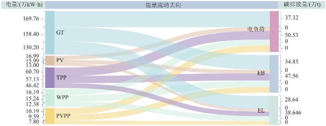
4.3 日运行的能流—碳流分析

为进一步直观呈现能源系统内各类电源及其对应碳排放的流向关系,图7展示了钢铁园区典型运行周期内的能碳流分摊情况,该图主要展示了系统内主要电源向不同终端用能对象传递电能的过程。从图7中可以看出,GT 发电承担了较大比例的园区供电任务,由于其天然气燃料属性,在碳排放中占据较高份额;TPP 提供了部分稳定电力,因其碳排放因子较高,同样成为系统中主要的碳排放来源之一;相对地,WPP 和 PVPP 则为系统提供了低碳电力,在供能至 EL 和 EB 路径上,起到了明显的碳削减作用。EB、EL 作为二次能量转换设备,其运行所输入的电能-碳流被系统准确分摊至其终端产出(热能与氢能),进而反映在热能碳排放因子与氢能碳排放因子的构成中。通过将输入电源与末端负荷建立碳排放分摊映射,展示了能量路径-碳排责任之间的因果关系,有助于识别主要碳源结构。其建模逻辑也体现了碳流守恒与按能分摊原则,验证了前文碳排放因子建模方法的合理性与物理一致性。

4.4 源-荷协同经济调度与低碳响应模型有效性分析

为验证所提模型的合理性与有效性,设立如下场景进行算例对比。
场景1:仅考虑上层经济调度,不考虑下层碳流响应。
场景2:考虑上层经济调度,下层仅考虑园区内部设备产能碳排放,不考虑市场化交易部分的碳排放。
本文场景:考虑上层经济调度与下层碳流响应,同时考虑园区内部设备产能与市场交易电量的碳排放。
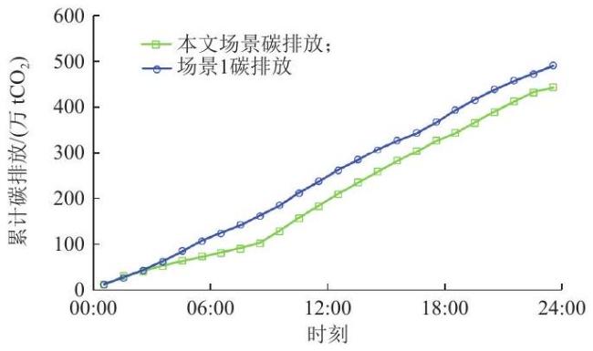
为验证所提模型的低碳引导效果,图8展示了两种场景下系统碳排放的时间累积趋势。本文所提场景将分时碳排放因子纳入负荷响应策略,同时明确纳入外部购电碳源,构建完整的碳排放边界。累计碳排放相较场景1具备显著降低趋势,说明分时碳排放因子具备时序引导作用,能够实现钢铁园区的低碳运行。
图7 日运行能流

Fig. 7 Sankey diagram of energy flow and carbon flow

图8 不同场景的 24 h 碳排放累积量

Fig. 8 24-hour cumulative carbon emissions under different scenarios

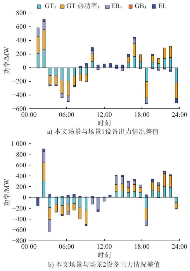
关键产能设备出力在不同场景下的差值对比如图9所示。若设备出力为正值,表示在本文场景下此设备出力高于对比场景,负值则表示在本文场景下设备出力被相对抑制。图9a)展示了在未引入分时碳排放因子引导机制(场景1)与引入分时碳排放因子(本文场景)下,关键设备的出力差异。 EB 在夜间(00:00—06:00、20:00—24:00)差值为负,在白天 PV 高峰期(10:00—16:00)差值转为正值。EL 在夜间(03:00—08:00)差值为负,在中午(09:00—13:00)差值为正。说明在引入分时碳排放因子后,系统主动调整两种设备在高碳电力时段的运行时间,避免使用火电驱动电热氢转换,转而集中在低碳电力富余时段运行。由于本文场景下系统在碳排放因子作用下负荷改变,整体抑制化石产能设备的出力,GT 大多数时段差值为负。尤其在夜间高碳负荷时段压制更为明显,表现出系统对高碳能流输入的主动规避趋势。
在未考虑市场购电碳排放的场景2中,系统忽略电力市场交易部分的碳排放,与本文场景对比可发现:相较于图9a),EB、EL 差值幅度扩大,表明在场景2中,系统错误地认为火电交易占比较多时段的电能碳清洁,导致两种设备在实际的高碳时段持续运行。而本文场景中,外购火电的碳排放被纳入参与园区内部整体调整,系统对 EB、EL 在高碳时段的运行进行了抑制。
图9 本文场景与不同场景的设备出力差值

Fig. 9 Output power variation of devices across different operational scenarios

GT 的夜间差值为负,说明在场景2中,系统因碳排放核算方式的不完整而低估整体碳负荷,导致经过下层低碳响应后的负荷情况改变不大,从而对 GT 的抑制不足;本文场景通过建立钢铁园区输入能源的完整的分时碳排放因子,提升系统总碳排放压力,抑制 GT 运行。

5 结论

本文围绕钢铁园区多能协同背景下的低碳运行问题,构建了考虑电-热-氢3类能量分时碳排放因子的源—荷协同优化模型。在建模过程中,引入能-碳流耦合机制,实现了对能量转换路径中碳排放属性的精细刻画。在优化方法上,采用上下层结构分别处理运行经济性与碳响应目标,通过迭代方式协调多能负荷与系统碳排放因子之间的反馈关系。本文的主要贡献在于:
1)突破了传统研究侧重电-热系统的局限。在钢铁园区背景下提出电-热-氢分时碳排放因子建模方法,并引入氢能负荷的碳排放溯源机制,使电源侧在日内 1 h 分辨率下的决策变量数量由120 增加至 360 个,实现碳排放核算的精细化;
2)拓展了钢铁园区碳排放核算范围。将电力
市场外购电源的碳属性显式纳入园区碳排放核算,建立了市场交易与园区能碳优化的联动机制,避免了对外购电源碳责任的低估。
算例结果表明,本文所提方法在低碳与经济协同优化方面具备有效性,具体结论如下:
1)碳排放显著降低。在引入分时碳排放因子后,电、热、氢 3 类负荷实现明显的时序转移,系统碳排放累计下降 10.8% 。
2)兼顾低碳与经济性的协同优化。相较于仅考虑经济调度的场景,所提协同优化策略在实现显著碳减排的同时,未牺牲系统运行经济性。
3)关键设备出力结构优化。 EB 与 EL 运行时段由夜间高碳时段转向白天风光出力富余时段,进一步提升了可再生能源利用率。
总体而言,本文提出的分时碳排放因子驱动的协同优化框架在降低钢铁园区碳排放水平的同时保持了良好的运行经济性。需要说明的是,本文在碳排放核算中主要侧重于能量维度的过程碳排,并未引入全生命周期碳核算框架,未来研究可进一步扩展碳排放因子的空间边界,结合区域能源替代、碳市场机制等因素,提升建模的完整性与现实性。
[1]
周专, 苗帅, 袁铁江. 提升风电消纳的绿氢钢铁冶炼系统动力学建模[J]. 中国电力, 2024, 57(8):36-45.

ZHOU Zhuan, MIAO Shuai, YUAN Tiejiang. System dynamics modeling of green hydrogen steel smelting to improve wind power consumption[J]. Electric Power, 2024, 57(8):36-45.

[2]
杨轶. 浅议我国钢铁产业园的发展现状[J]. 中国钢铁业, 2022(10):10-14, 30.

[3]
周天睿, 康重庆, 徐乾耀, 等. 电力系统碳排放流分析理论初探[J]. 电力系统自动化, 2012, 36(7):38-43, 85.

ZHOU Tianrui, KANG Chongqing, XU Qianyao, et al. Preliminary theoretical investigation on power system carbon emission flow[J]. Automation of Electric Power Systems, 2012, 36(7):38-43, 85.

[4]
周天睿, 康重庆, 徐乾耀, 等. 电力系统碳排放流的计算方法初探[J]. 电力系统自动化, 2012, 36(11):44-49.

ZHOU Tianrui, KANG Chongqing, XU Qianyao, et al. Preliminary investigation on a method for carbon emission flow calculation of power system[J]. Automation of Electric Power Systems, 2012, 36(11):44-49.

[5]
李姚旺, 张宁, 杜尔顺, 等. 基于碳排放流的电力系统低碳需求响应机制研究及效益分析[J]. 中国电机工程学报, 2022, 42(8): 2830-2841.

LI Yaowang, ZHANG Ning, DU Ershun, et al. Mechanism study and benefit analysis on power system low carbon demand response based on carbon emission flow[J]. Proceedings of the CSEE, 2022, 42(8): 2830-2841.

[6]
陈达, 鲜文军, 吴涛, 等. 混合电力市场下碳排放流的分配[J]. 电网技术, 2016, 40(6):1684-1689.

CHEN Da, XIAN Wenjun, WU Tao, et al. Allocation of carbon emission flow in hybrid electricity market[J]. Power System Technology, 2016, 40(6):1684-1689.

[7]
杨挺, 党兆帅, 王旭东, 等. 混合交易模式下电力系统全环节碳排放核算方法[J]. 中国电机工程学报, 2025, 45(1):38-51.

YANG Ting, DANG Zhaoshuai, WANG Xudong, et al. Carbon emission accounting method for the entire electricity system in the mixed trading model[J]. Proceedings of the CSEE, 2025, 45(1): 38-51.

[8]
李汶龙, 周云, 罗裬, 等. 计及现货交易的电能量交易全环节用电碳责任分摊[J]. 中国电力, 2024, 57(5):99-112.

LI Wenlong, ZHOU Yun, LUO Ling, et al. Carbon allocation throughout the entire process of electric energy trading considering spot trading[J]. Electric Power, 2024, 57(5):99-112.

[9]
CHENG Y H, ZHANG N, WANG Y, et al. Modeling carbon emission flow in multiple energy systems[J]. IEEE Transactions on Smart Grid, 2019, 10(4):3562-3574.

[10]
HUANG J H, DUAN W Y, ZHOU Q, et al. Methodology for carbon emission flow calculation of integrated energy systems[J]. Energy Reports, 2022, 8:1090-1097.

[11]
杨彪, 谭洪, 朱建川, 等. 面向电-氢本地能源市场的综合能源系统优化运行模型[J]. 电力系统自动化, 2026, 50(10):182-190.

YANG Biao, TAN Hong, ZHU Jianchuan, et al. Optimal operation model of integrated energy systems for electricity-hydrogen local energy markets[J]. Automation of Electric Power Systems, 2026, 50(10):182-190.

[12]
张玉敏, 孙鹏凯, 孟祥剑, 等. 基于碳势-能源价格双响应的综合能源系统低碳经济调度[J]. 电力系统自动化, 2024, 48(9):21-33.

ZHANG Yumin, SUN Pengkai, MENG Xiangjian, et al. Low-carbon economic dispatching of integrated energy system based on dual response of carbon intensity and energy price[J]. Automation of Electric Power Systems, 2024, 48(9):21-33.

[13]
张鹏成, 徐箭, 柯德平, 等. 氢能驱动下钢铁园区能源系统优化配置[J]. 电力系统自动化, 2022, 46(14):1-10.

ZHANG Pengcheng, XU Jian, KE Deping, et al. Optimal configuration of energy system in iron and steel park driven by hydrogen energy[J]. Automation of Electric Power Systems, 2022, 46(14):1-10.

[14]
苗秋愿, 邢海军. 基于机会约束的风光荷储热灵活性资源优化调度[J]. 浙江电力, 2025, 44(8):54-65.

MIAO Qiuyuan, XING Haijun. Optimal scheduling of WPLSH flexibility resources based on chance constraints[J]. Zhejiang Electric Power, 2025, 44(8):54-65.

[15]
张笑演, 王橹裕, 黄蕾, 等. 考虑扩展碳排放流和碳交易议价模型的园区综合能源优化调度[J]. 电力系统自动化, 2023, 47(9):34-46.

ZHANG Xiaoyan, WANG Luyu, HUANG Lei, et al. Optimal dispatching of park-level integrated energy system considering augmented carbon emission flow and carbon trading bargain model[J]. Automation of Electric Power Systems, 2023, 47(9): 34-46.

[16]
顾佳, 魏业文. 计及低碳-超碳需求响应的电力系统日前-日内两阶段优化调度[J]. 现代电子技术, 2025, 48(8):100-108.

GU Jia, WEI Yewen. Power systems day-ahead and intra-day two-stage optimization dispatch considering low-carbon and ultra-low carbon demand response[J]. Modern Electronics Technique, 2025, 48(8):100-108.

[17]
许乐, 徐玉韬, 袁旭峰, 等. 计及动态碳排的含氢综合能源系统低碳调度[J]. 电网与清洁能源, 2025, 41(2):120-129.

XU Le, XU Yutao, YUAN Xufeng, et al. Low-carbon dispatching of hydrogen-based integrated energy systems considering dynamic carbon emissions[J]. Power System and Clean Energy, 2025, 41(2): 120-129.

[18]
刘子腾, 赵建立, 陶伟健, 等. 基于 V2B 技术的智能楼宇分布式能源管理策略[J]. 综合智慧能源, 2025, 47(11):24-35.

LIU Ziteng, ZHAO Jianli, TAO Weijian, et al. Distributed energy management strategy for smart buildings based on V2B technology[J]. Integrated Intelligent Energy, 2025, 47(11):24-35.

[19]
闫越, 冯皓然, 郭逸涵, 等. 面向低碳需求响应的短流程钢铁企业最优用电策略[J]. 浙江电力, 2025, 44(5):90-100.

YAN Yue, FENG Haoran, GUO Yihan, et al. An optimal electricity consumption strategy for steel enterprises with short processes in the context of low-carbon DR[J]. Zhejiang Electric Power, 2025, 44(5): 90-100.

[20]
张玉敏, 孙鹏凯, 吉兴全, 等. 考虑扩展碳排放流的综合能源系统低碳经济调度[J]. 电网技术, 2023, 47(8):3174-3183.

ZHANG Yumin, SUN Pengkai, JI Xingquan, et al. Low-carbon economic dispatch of integrated energy system with augmented carbon emission flow[J]. Power System Technology, 2023, 47(8): 3174-3183.

[21]
傅铮, 王峰, 王若宇, 等. 基于时序生产模拟的需求侧响应促进新能源消纳量化分析[J]. 浙江电力, 2024, 43(9):39-48.

FU Zheng, WANG Feng, WANG Ruoyu, et al. Quantitative analysis of renewable energy consumption promoted by demand-side re-sponse based on time-series production simulation[J]. Zhejiang Electric Power, 2024, 43(9):39-48.

[22]
赵宏飞, 马秀娟, 马添翼, 等. 基于碳手印方法的工业过程降碳改造研究[J]. 浙江电力, 2024, 43(3):122-129.

ZHAO Hongfei, MA Xiujuan, MA Tianyi, et al. Research on carbon reduction transformation in industrial processes based on carbon handprint method[J]. Zhejiang Electric Power, 2024, 43(3):122-129.

[23]
张敏, 郭翔宇, 常潇, 等. 碳-绿证交易机制下计及分布式储能的虚拟电厂经济性分析[J]. 中国电力, 2026, 59(1):20-32.

ZHANG Min, GUO Xiangyu, CHANG Xiao, et al. Economic analysis of virtual power plants incorporating distributed energy storage in carbon-green certificate trading mechanisms[J]. Electric Power, 2026, 59(1):20-32.

[24]
许传博, 李沛遥, 张文座, 等. 面向电-碳-氢-醇协同的海上综合能源岛规划[J]. 南方能源建设, 2025, 12(3):52-66.

XU Chuanbo, LI Peiyao, ZHANG Wenzuo, et al. Planning for offshore integrated energy islands with electricity-carbon-hydrogen-methanol synergy[J]. Southern Energy Construction, 2025, 12(3): 52-66.

[25]
孙笑天, 卫志农, 陈胜, 等. 考虑碳流需求响应的园区低碳经济运行策略[J]. 电力建设, 2025, 46(5):84-95.

SUN Xiaotian, WEI Zhinong, CHEN Sheng, et al. Strategy for low-carbon economic operation in industrial parks considering carbon flow demand response[J]. Electric Power Construction, 2025, 46(5): 84-95.

[26]
彭宏香, 陈曦. 计及需求响应的含电-氨-电环节综合能源系统多时间尺度电-热联合调度[J]. 现代电子技术, 2025, 48(10):109-117.

PENG Hongxiang, CHEN Xi. Electricity-ammonia-electricity link IES multi-time-scale electricity-heat joint scheduling considering DR[J]. Modern Electronics Technique, 2025, 48(10):109-117.

[27]
张昊, 米阳, 陈耀威, 等. 基于混合博弈的含多产消者虚拟电厂优化运行策略[J]. 浙江电力, 2026, 45(2):60-71. ZHANG Hao,MI Yang,CHEN Yaowei,et al. A hybrid game-based

optimal operation strategy for virtual power plants with multiprosumer participation[J]. Zhejiang Electric Power, 2026, 45(2): 60-71.

[28]
李梦露, 德格吉日夫. 计及储能运营商的工业园区微网协同优化运行研究[J]. 综合智慧能源, 2025, 47(12):57-65.

LI Menglu, Degejirifu. Research on coordinated optimized operation of microgrids in industrial parks considering energy storage operators[J]. Integrated Intelligent Energy, 2025, 47(12):57-65.

[29]
张嘉蕾, 冯浩然, 宣文举, 等. 考虑需求响应和绿证-碳排放交易联动机制的电力系统双层调度策略[J]. 湖南电力, 2025, 45(6): 97-106.

ZHANG Jialei, FENG Haoran, XUAN Wenju, et al. Two-layers scheduling strategy of power system considering demand response and green certificate-carbon emission trading linkage mechanism[J]. Hunan Electric Power, 2025, 45(6):97-106.

[30]
郭康壮, 赵俊, 李海斌, 等. 考虑碳交易和需求响应的虚拟电厂低碳经济调度[J]. 分布式能源, 2025, 10(2):69-80.

GUO Kangzhuang, ZHAO Jun, LI Haibin, et al. Low carboneconomic dispatch of virtual power plants considering carbon trading and demand response[J]. Distributed Energy, 2025, 10(2):69-80.

[31]
刘卫东, 邓晖, 贾兴, 等. 浙江电力市场价格传导体系建设思考与实践[J]. 中国电力, 2026, 59(1):133-142.

LIU Weidong, DENG Hui, JIA Xing, et al. Thoughts and practices on the construction of the electricity price transmission system in Zhejiang power market[J]. Electric Power, 2026, 59(1):133-142.

Options
Outlines

/