
Carbon-Based Composite Absorbing Materials
Received date: 2023-08-15
Revised date: 2023-11-12
Online published: 2024-03-15
Supported by
National Natural Science Foundation of China(12175089)
National Natural Science Foundation of China(12205127)
Key Research and Development Program of Yunnan Province(202103AF140006)
Applied Basic Research Programs of Yunnan Provincial Science and Technology Department(202001AW070004)
Applied Basic Research Programs of Yunnan Provincial Science and Technology Department(202301AS070051)
Applied Basic Research Programs of Yunnan Provincial Science and Technology Department(202301AU070064)
Yunnan Industrial Innovative Talents Program for "Xingdian Talent Support Plan"(KKXY202252001)
Yunnan Program for Introducing Foreign Talents(202305AO350042)
Yunnan Major Scientific and Technological Projects(202202AG050003)
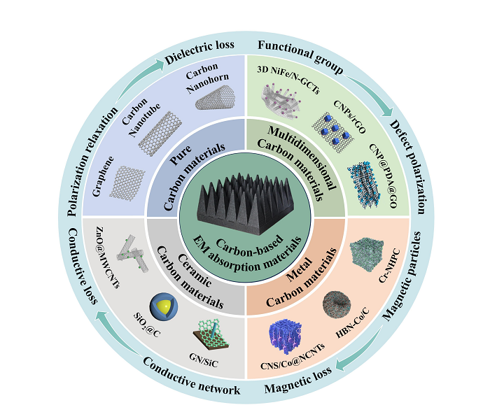
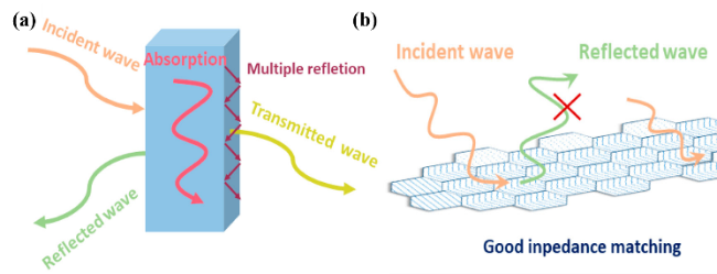
with the rapid development of radio waves and electronic information technology,the problem of electromagnetic radiation pollution is becoming more and more prominent,which has attracted wide attention around the world.in order to solve the problem of electromagnetic pollution,people are committed to researching and developing electromagnetic wave-absorbing materials with light weight,thin thickness,a wide frequency band,and strong absorption.Compared with traditional wave-absorbing materials,carbon-based composite wave-absorbing materials have excellent dielectric properties,special microstructure,good impedance matching and efficient wave-absorbing properties,and can effectively reduce the mass of composite materials,which has great development potential In the field of wave-absorbing materials,and has gradually become a research hotspot.In this paper,the basic absorption principle of electromagnetic wave is summarized from the aspects of impedance matching and loss mechanism,and the research progress of carbon-carbon,carbon-metal/metal oxide,carbon-ceramics and other kinds of carbon-based composite absorbing materials is reviewed.At the same time,the synthesis methods,absorption properties and attenuation mechanism of these carbon-based composite absorbing materials are reviewed.Finally,the shortcomings of carbon-based composite absorbing materials in electromagnetic wave absorption are discussed and possible solutions are put forward,and the future development direction of carbon-based composite absorbing materials is prospected。
1 Introduction
2 Absorbing mechanism and classification of absorbing materials
2.1 Absorbing mechanism
2.2 Classification of absorbing materials
3 Carbon nano-absorbing materials
4 Carbon-based composite absorbing materials
4.1 carbon-carbon composite absorbing materials
4.2 Carbon-metal/metal oxide composite absorbing materials
4.3 Carbon-ceramic composite absorbing materials
5 Conclusion and outlook
Lu Shuiqing , Liu Yichang , Xie Zhipeng , Zhang Da , Yang Bin , Liang Feng . Carbon-Based Composite Absorbing Materials[J]. Progress in Chemistry, 2024 , 36(4) : 556 -574 . DOI: 10.7536/PC230814
表1 Comparison of microwave absorbing properties of carbon materialsTable 1 Comparison of the electromagnetic wave absorption performance of carbon materials |
| Different carbon materials | Synthesis method | Thickness /mm | Reflection loss/dB | Absorption bandwidth /GHz | Ref. |
|---|---|---|---|---|---|
| rGO | Chemical reduction | 2 | −6.9 | / | 58 |
| Graphene foam | Solvent heat | 10 | −27 | 4.2 | 68 |
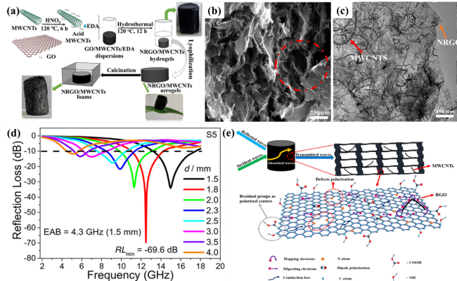
| NRGO/MWCNT | Hydrothermal method | 1.5 | −69.6 | 4.3 | 69 |
| ERG | Chemical vapor deposition | 3.75 | −26.7 | 4.2 | 72 |
| NCMCCS | Solvent heat | 3.7 | −60.4 | 7.2 | 73 |
| Metal-free CNTs | Chemical vapor deposition | 3.5 | −22.4 | 1.5 | 74 |
| CNTs/PyC | Template method | 6.6 | −29.6 | 4.2 | 75 |
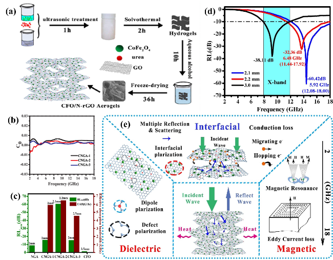
图7 CFO/N-rGO气凝胶(CNGA)的 (a) 合成路线图;(b) C0-f曲线;(c) 吸波性能对比图;(d) CNGA-2反射损耗图;(e) 吸波机理示意图[104,105]Fig. 7 (a) Schematic illustration of the synthetic route, (b) the C0-f curves, (c) Absorption performance comparison, (d) Reflection loss diagram of CNGA-2, (e) Schematic illustration on wave absorption mechanism of CFO/N-rGO aerogel (CNGA)[104,105] |
表2 Comparison of electromagnetic wave absorption properties of different carbon matrix compositesTable 2 Comparison of electromagnetic wave absorption performance of various carbon-based composited materials |
| Carbon-based composite absorbing materials | Synthesis method | Thickness /mm | Reflection loss/dB | Absorption bandwidth /GHz | Ref. |
|---|---|---|---|---|---|
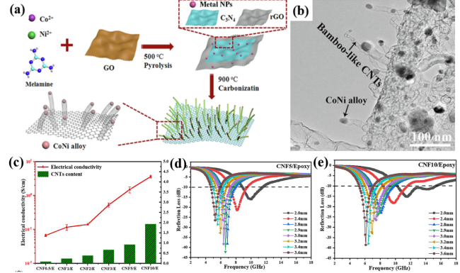
| CNT5/Epoxy | Hydrothermal method | 2.9 | −42.13 | 1.6 | 81 |
| CNPs/rGO | In-situ pyrolysis | 2.89 | −66.2 | 14.8 | 82 |
| GN/CS | Liquid-phase method | 1.5 | −28.1 | 5.7 | 83 |
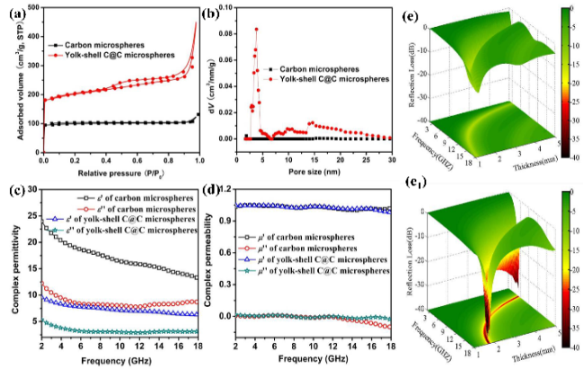
| Yolk-shell C@C | Co-precipitation, Etching | 2 | −34.8 | 5.4 | 84 |
| MWCNTs/Fe3O4 | Hydrothermal method | / | −18.22 | / | 87 |
| Fe3O4/rGO | Hydrothermal method | 3.5 | −45 | 3.2 | 88 |
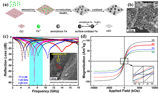
| Amorphous Fe/RGO | Solvent heat | 3.26 | −72.8 | 5.9 | 89 |
| C@Fe@Fe3O4 | Template method, Pyrolysis | 1.5 | −40 | 5.2 | 90 |
| FeCoNi@GO | Chemical plating | 2.33 | −68 | 8.4 | 91 |
| Co3O4/rGO | Hydrothermal method | 3.6 | −45.15 | 7.14 | 92 |
| Fe3O4/S-GO | Solvent heat | 2 | −41 | 5.3 | 93 |
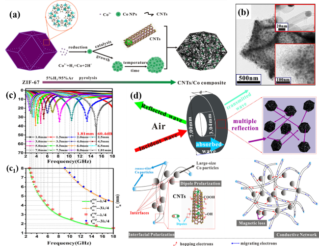
| CNTs/Co | In-situ pyrolysis | 1.81 | −60.4 | 5.2 | 98 |
| CoFe2O4/CNTs | Solvent heat | / | −15.7 | 2.5 | 103 |
| CoFe2O4/N-rGO | Solvent heat | 2.2 | −60.4 | 6.48 | 104 |
| rGO/CoFe2O4 | Hydrothermal method | 2.3 | −47.9 | 5 | 107 |
| MWCNTs/ZnFe2O4 | Hydrothermal method | 1.5 | −55.5 | 3.6 | 109 |
| CoFe2O4@GO | Solvent heat | 2 | −42 | 12.9 | 110 |
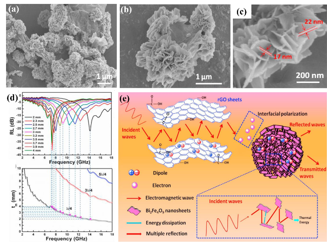
| Bi2Fe4O9/rGO | One-step etching | 2 | −71.88 | 13.8 | 111 |
| BiFeO3/rGO | One-step etching | 1.8 | −46.7 | 4.7 | 112 |
| CNT/EG/BF | Sol-gel method | 2 | −26.1 | 8.2 | 113 |
| Cu0.25Ni0.25Zn0.5Fe2O4/ MWCNTs | Co-precipitation | 2.5 | −37.7 | / | 114 |
| Co0.2Ni0.4Zn0.4Fe2O4/GN | Hydrothermal method | / | −58.3 | 14.8 | 115 |
| N-rGO/Ni0.5Zn0.5Fe2O4 | Solvent heat | 2.91 | −63.2 | 5.4 | 116 |
| G/SiOC | Polymer pyrolysis | 2.35 | −69.3 | 3.9 | 124 |
| MWCNTs/SiO2 | Ultrasonic method | 3.5 | −60.54 | 4.2 | 125 |
| rGO/SiO2 | Cold pressing method | 2.1 | −42 | 4.2 | 126 |
| Mo2C@C | Pyrolysis | 1.9 | −48 | 4.1 | 128 |
| [1] |
|
| [2] |
|
| [3] |
|
| [4] |
|
| [5] |
|
| [6] |
|
| [7] |
|
| [8] |
|
| [9] |
|
| [10] |
|
| [11] |
|
| [12] |
|
| [13] |
|
| [14] |
|
| [15] |
( 乔瑶雨, 张学辉, 赵晓竹, 李超, 何乃普. 化学进展, 2022, 34(5): 1181.)
|
| [16] |
|
| [17] |
|
| [18] |
|
| [19] |
|
| [20] |
|
| [21] |
|
| [22] |
( 杨旺, 蒋波, 车赛, 闫璐, 李正轩, 李永峰. 新型炭材料, 2021, 36(6): 1016.)
|
| [23] |
|
| [24] |
|
| [25] |
|
| [26] |
|
| [27] |
|
| [28] |
|
| [29] |
|
| [30] |
|
| [31] |
|
| [32] |
|
| [33] |
|
| [34] |
|
| [35] |
|
| [36] |
|
| [37] |
|
| [38] |
|
| [39] |
|
| [40] |
|
| [41] |
|
| [42] |
|
| [43] |
|
| [44] |
|
| [45] |
|
| [46] |
( 祁文青. 压电与声光, 2018, 40(4): 633.)
|
| [47] |
|
| [48] |
|
| [49] |
|
| [50] |
( 杨期鑫, 俞璐军, 董余兵, 傅雅琴, 朱曜峰. 新型炭材料, 2019, 34(5): 455.)
|
| [51] |
|
| [52] |
|
| [53] |
|
| [54] |
|
| [55] |
|
| [56] |
|
| [57] |
|
| [58] |
|
| [59] |
|
| [60] |
|
| [61] |
|
| [62] |
|
| [63] |
|
| [64] |
|
| [65] |
|
| [66] |
|
| [67] |
|
| [68] |
|
| [69] |
|
| [70] |
|
| [71] |
|
| [72] |
|
| [73] |
|
| [74] |
|
| [75] |
|
| [76] |
|
| [77] |
|
| [78] |
( 康怡然, 蔡锋, 陈宏源, 陈名海, 张锐, 李清文. 化学进展, 2014, 26(09): 1562.)
|
| [79] |
|
| [80] |
|
| [81] |
|
| [82] |
|
| [83] |
|
| [84] |
|
| [85] |
|
| [86] |
|
| [87] |
( 侯翠岭, 李铁虎, 赵廷凯, 刘和光, 刘乐浩, 张文娟. 新型炭材料, 2013, 28(3): 184.)
|
| [88] |
|
| [89] |
|
| [90] |
|
| [91] |
|
| [92] |
|
| [93] |
|
| [94] |
|
| [95] |
|
| [96] |
|
| [97] |
|
| [98] |
|
| [99] |
|
| [100] |
|
| [101] |
|
| [102] |
|
| [103] |
|
| [104] |
|
| [105] |
|
| [106] |
|
| [107] |
|
| [108] |
|
| [109] |
|
| [110] |
|
| [111] |
|
| [112] |
|
| [113] |
|
| [114] |
|
| [115] |
|
| [116] |
|
| [117] |
|
| [118] |
( 叶凯, 梁风, 姚耀春, 马文会, 杨斌, 戴永年. 材料导报, 2019, 33(7): 1089.)
|
| [119] |
|
| [120] |
|
| [121] |
|
| [122] |
|
| [123] |
|
| [124] |
|
| [125] |
|
| [126] |
|
| [127] |
|
| [128] |
|
| [129] |
|
/
| 〈 |
|
〉 |