
Polymeric Porous Surface Materials: Construction and Drug Delivery Applications
Received date: 2023-10-07
Revised date: 2024-01-03
Online published: 2024-02-12
Supported by
National Natural Science Foundation of China(U20A20262)
National Natural Science Foundation of China(51933009)
National Natural Science Foundation of China(52203190)
Fundamental Research Funds for the Central Universities(226-2023-00108)
combination products present significant opportunities for advancing traditional medical devices by versatile integration of therapeutic drugs and devices.as clinical needs evolve,there remains growing interest in developing new surface and interface engineering technologies for modulating drug delivery behavior.Recently,polymeric porous surface interface technology has emerged As a robust strategy for the flexible amalgamation of functional molecules with medical devices via capillary adsorption.in comparison to the conventional coating method,This technology shows distinctive features like flexible loading,facile dosage control,and tunable release,therefore providing a novel insight for personalized medicine.This review begins by outlining the methods for preparing porous surfaces of polymer materials,including the breath figure,template method,surface non-solvent-induced phase separation,stimulus-induced phase separation method,and electrospinning method.Then,the mechanism for the capillary-based loading process and hindered release behavior of functional species,which play a central role in the development of spongy surface-based Combination devices,is discussed.This review also provides an overview of the latest research on the porous surface interfaces of polymer materials in applications like targeted anti-cancer,cardiovascular implants,and bone repair,summarizes the present challenges in research on the porous surfaces of polymer materials,and highlights insights into potential future directions。
1 Introduction
2 Construction strategy of porous surface on polymer materials
2.1 Breath figure
2.2 Template method
2.3 Surface non solvent induced phase separation
2.4 Stimulus-induced phase separation
2.5 Electrospinning method
3 Functional molecule delivery based on porous polymer surface
3.1 The driving force of loading and release of functional molecules
3.2 Study on the release behavior of functional molecules
4 Application of polymer porous surface in drug delivery
4.1 Targeted anti-cancer
4.2 Cardiovascular diseases
4.3 Orthopedics diseases
5 Conclusion

Key words: combination products; porous materials; surface engineering; drug delivery
Yanchen Chen , Honglin Qian , Yirong Guo , Jing Wang , Jian Ji . Polymeric Porous Surface Materials: Construction and Drug Delivery Applications[J]. Progress in Chemistry, 2024 , 36(5) : 679 -695 . DOI: 10.7536/PC230919
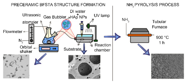
图1 超声喷涂辅助的呼吸图法。氮气流量计连接装有纳米粒子/水溶液的气体起泡器,起泡器内的超声波雾化器通过空化效应产生包含纳米粒子的水气,水气被输送到含有基材和紫外光的反应室中,从而在基材表面形成蜂窝状孔洞;后续该基材可以通过氨气环境的热解过程进一步转化为氮氧化硅[28]Fig. 1 Ultrasonic spray assisted breathing figure method. The nitrogen flowmeter is connected to a gas bubbler containing nanoparticles/aqueous solution. The ultrasonic atomizer inside the bubbler generates water vapor containing nanoparticles through the cavitation effect, which is then transported to a reaction chamber containing a substrate and UV light to form honeycomb holes. Subsequently, it can be further transformed into silicon nitride by pyrolysis process in ammonia environment[28] |
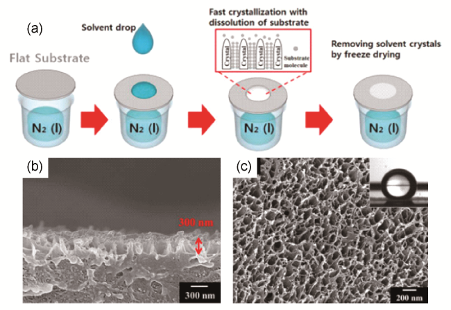
图3 极快冰模板法:(a)溶剂在表面极快溶解和定向熔融结晶的示意图;(b, c)为多孔PS表面横截面和表面的SEM图像[33]Fig. 3 Extremely fast ice templating process. (a) Schematic diagram of extremely fast solvent dissolution and directional melt crystallization on the surface; (b) and (c) are the SEM images of porous PS surface cross section and surface[33] |
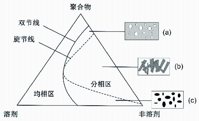
图4 非溶剂诱导相分离法三元相图:(a)贫聚合物相成核(双节线分相);(b)双连续结构(旋节线分相);(c)富聚合物相成核(双节线分相)[18]Fig. 4 Ternary phase diagram for nonsolvent-induced phase separation. (a) Nucleation of polymer-poor phase (binodal phase separation); (b) bicontinuous structure (spinodal phase separation); (c) nucleation of polymer-rich phase (binodal phase separation)[18] |
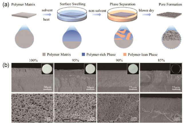
图5 (a)表面溶胀非溶剂诱导相分离法制备多孔表界面示意图。聚合物基材被依次浸入溶剂和非溶剂中,通过相分离形成孔洞;(b)不同浓度的DMF与水混合物作为溶剂制备的PMMA多孔断面的SEM图像[11]Fig. 5 (a) Schematic diagram of porous surface/interface prepared by surface swelling non-solvent-induced phase separation;(b) SEM image of porous surface of PMMA prepared with different concentrations of DMF and water mixture as solvent[11] |
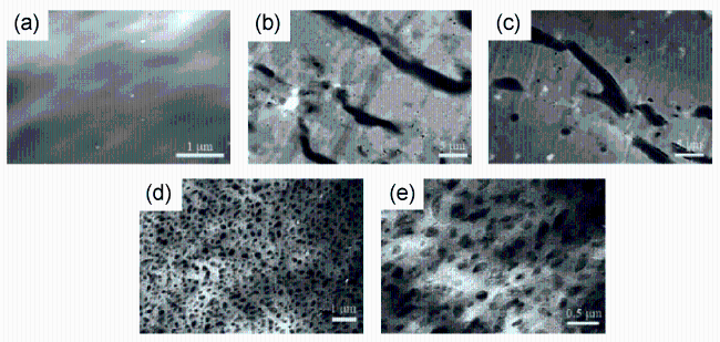
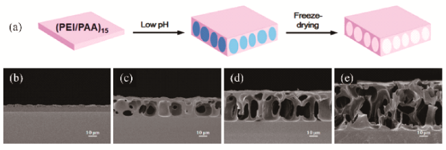
图6 刺激诱导相分离法制备多孔涂层示意图。将无孔(PEI/PAA)自组装膜浸入酸性溶液(pH=2.9)中以诱导孔形成,然后冷冻干燥以除去水。(b~e)分别为在酸性溶液中浸泡0、30、60和90 min的薄膜的SEM横截面图像[43]Fig. 6 Schematic diagram of preparation of porous coatings by stimulus-induced phase separation. Poreless (PEI/PAA) self-assembled membranes were immersed in an acidic solution (pH=2.9) to induce pore-formation, then freeze-dried to remove water. (b~e) SEM cross-section images of films soaked in acidic solution for 0, 30, 60 and 90 min, respectively[43] |
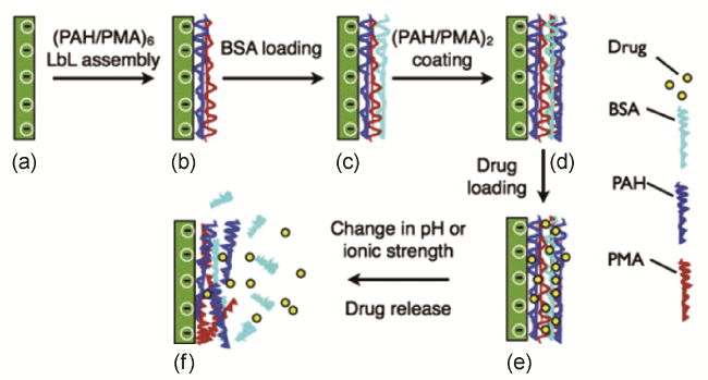
图7 通过刺激诱导相分离来传递药物分子的PEM薄膜制备方法示意图:(a)玻璃基板;(a~b) LbL沉积(PAH/PMA);(b~c) BSA装载;(c~d) 附加(PAH/PMA);(d~e) CH加载;(e~f),刺激响应释放[42]Fig. 7 Schematic diagram of the preparation of PEM films for the delivery of the drug and protein by stimulus-induced phase separation. (a) A glass substrate; (a~b) LbL deposition (PAH/PMA); (b~c) BSA loading; (c~d) LbL deposition again (PAH/PMA); (d~e) CH loading; (e~f) stimulus-response release[42] |
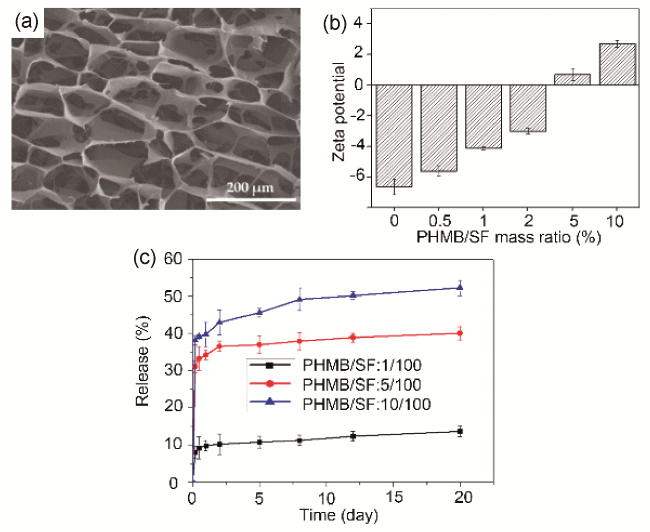
图10 静电相互作用加强物理吸附:(a)多孔PHMB/SF海绵横截面的SEM图像;(b) 不同质量比的PHMB/SF复合物的Zeta电位,SF的负电荷被PHMB中和,表明二者通过静电相互作用结合;(c) PHMB/SF海绵释放曲线图[73]Fig. 10 Physical adsorption enhanced by electrostatic interaction. (a) SEM image of the cross section of porous PHMB/SF sponge; (b) the Zeta potential of the PHMB/SF complex at different mass ratios, where the negative charge of SF is neutralized by PHMB, indicating that the binding is through electrostatic interaction; (c) the release curve of PHMB/SF sponge[73] |
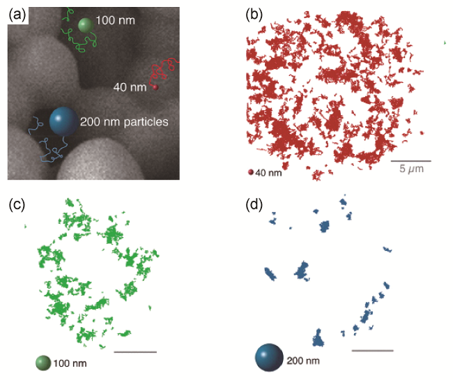
图11 不同粒径的微粒在同样孔径的多孔介质中扩散的可视化实验:(a)多孔介质的孔径为3.1 μm;(b)粒径40 nm的微粒在多孔介质中的扩散轨迹;(c)粒径100 nm的微粒在多孔介质中的扩散轨迹;(d)粒径200 nm的微粒在多孔介质中的扩散轨迹[67]Fig. 11 Visual experiment of diffusion of different particle sizes in porous media with the same aperture. (a) The pore size of the porous medium is 3.1 μm; (b) diffusion trajectory of particles with a particle size of 40 nm in porous media; (c) diffusion trajectory of 100 nm particles in porous media; (d) diffusion trajectory of 200 nm particles in porous media[67] |
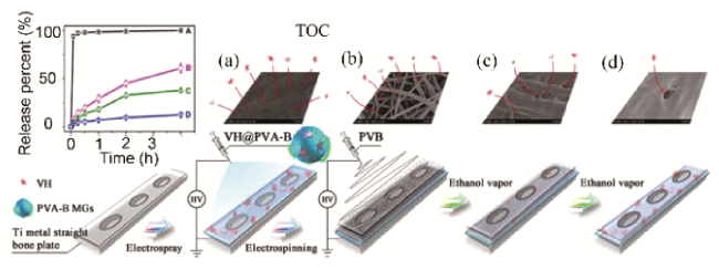
图12 聚合物薄膜和多孔纤维毡复合结构用于控制药物分子的释放:(a)钛金属直骨板表面喷涂载有盐酸万古霉素的聚乙烯醇-硼砂微凝胶(VH@PVA-B);(b)在微凝胶表面再喷一层多孔聚乙烯醇缩丁醛纤维毡(PVB),一定程度阻止药物分子释放;(c, d)并且可以通过乙醇蒸气处理,调节纤维毡的多孔结构[81]Fig. 12 Polymer film and porous fiber felts composite structure to control the release of drug molecules. (a) The surface of Ti metal straight bone plate was sprayed with vancomycin hydrochloride-loaded polyvinyl alcohol-borax microgel (VH@PVA-B); (b) spray another layer of porous polyvinyl butyral fiber felts on the surface of the microgel to block the release of drug molecules; (c, d) the porous structure of the fiber felts can be adjusted by ethanol steam treatment[81] |
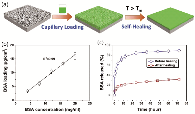
图13 动态自愈合多孔涂层示意图与表征:(a)负载功能分子后,通过温和的热触发方式进行孔洞的封闭,将功能分子包埋在孔洞中;(b)分子负载量与分子溶液浓度成正比;(c)自修复后分子释放速率显著减小[31]Fig. 13 Schematic and characterization of the dynamic self-healing porous coating. (a) After loading the molecules, the pores are closed by mild thermal triggering, then the molecules are embedded in the pores; (b) the molecular loading is proportional to the molecular solution concentration; (c) the molecular release rate is significantly reduced after self-healing[31] |
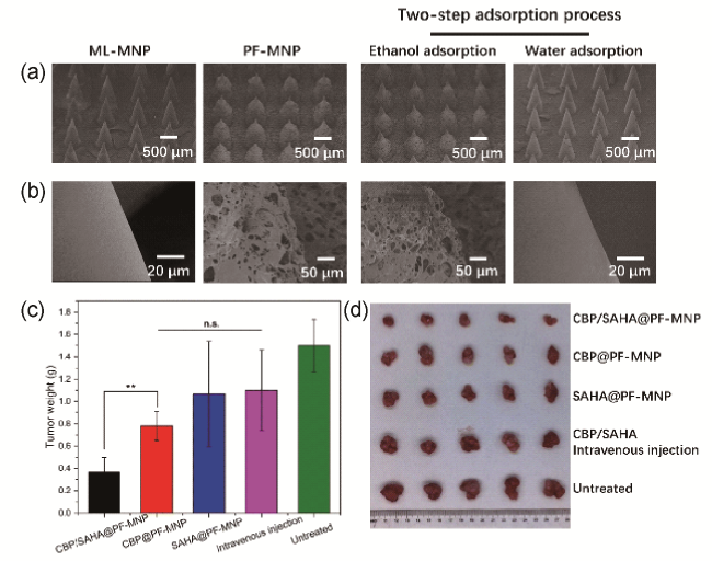
图14 多孔海绵涂层微针负载多种药物来治疗黑色素瘤。ML-MNP(无涂层微针)、PF-MNP(多孔海绵涂层微针)和PF-MNP吸附乙醇和水后的整体(a)和部分(b)形貌的SEM图像;(c)治疗21天后从不同组的5组小鼠中分离出的肿瘤重量;(d)治疗21天后五组孤立肿瘤的图像[95]Fig. 14 Porous sponge-coated microneedles are loaded with multiple drugs to treat melanoma. SEM images of the overall (a) and partial (b) morphology of ML-MNP (uncoated microneedles), PF-MNP (porous sponge-coated microneedles) and PF-MNP after adsorbing ethanol and water; (c) weight of tumors isolated from five groups of mice in different groups after 21 days of treatment; (d) images of isolated tumors in five groups after 21 days of treatment[95] |
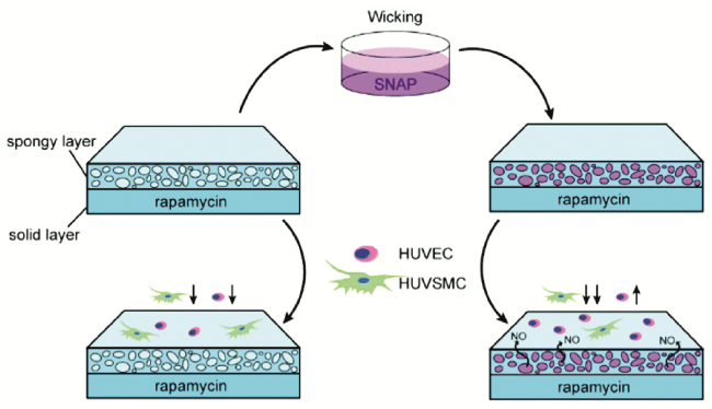
图15 NO加载和释放到雷帕霉素涂层中并调节细胞行为示意图。仅有雷帕霉素的涂层会同时抑制内皮细胞和平滑肌细胞的生长,NO的引入使受损的ECs得到恢复,而SMCs的生长进一步减少[101]Fig. 15 Schematic diagram of loading and releasing NO into rapamycin coating and regulating cell behavior. Only the coating of rapamycin inhibited the growth of both endothelial cells and smooth muscle cells, while the introduction of NO restored the damaged ECs and further reduced the growth of SMCs[101] |
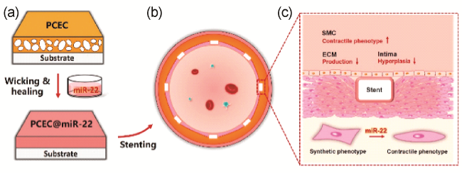
图16 动态自愈合多孔涂层递送基因药物miR-22:(a)多孔涂层负载miR-22后进行自愈合来闭合孔洞;(b)血管内植入支架示意图;(c)递送的miR-22使得平滑肌细胞(SMC)收缩表型改善、细胞外基质(ECM)分泌减少和内膜增生减少[87]Fig. 16 Dynamic self-healing porous coating for miR-22 gene drug delivery. (a) The porous coating was loaded with miR-22 and self-healed to close the holes; (b) diagram of stent placement in blood vessels; (c) MiR-22 improved SMC systolic phenotype, decreased ECM secretion, and decreased endometrial hyperplasia[87] |
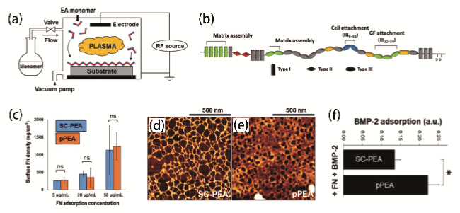
图17 超低剂量生长因子递送技术:(a)定制的等离子体聚合室示意图;(b)FN结构,显示其三种结构域类型(Ⅰ, Ⅱ, Ⅲ)和功能;(c)不同浓度的FN吸附在SC-PEA和pPEA上1 h的表面密度;FN在(d)SC-PEA和(e)pPEA上吸附10 min后的AFM相图。在SC-PEA上观察到薄的纤维网络,而在pPEA上观察到厚的,密集的网络;(f)BMP-2在fn包被表面的相对吸附量[109]Fig. 17 Ultralow dose growth factor delivery technology. (a) Schematic diagram of a customized plasma polymerization chamber; (b) FN structure, showing its three domain types (Ⅰ, Ⅱ, Ⅲ) and functions; (c) surface densities of FN adsorbed at different concentrations on SC-PEA and pPEA for 1 h; AFM phase diagram of FN adsorbed on (d) SC-PEA and (e) pPEA for 10 min. Thin fiber networks were observed on SC-PEA, while thick, dense networks were observed on pPEA. (f) The relative adsorption capacity of BMP-2 on FN coated surface[109] |
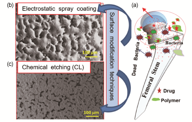
图18 表面多孔的髋臼杯衬垫:(a)髋臼杯衬垫抗菌示意图;(b)静电喷涂法制备的多孔结构表面SEM图像;(c)化学蚀刻法制备的多孔结构表面SEM图像[113]Fig. 18 Acetabulum cup liner with porous surface. (a) Antibacterial diagram of acetabular cup liner; (b) SEM images of porous surface prepared by electrostatic spraying; (c) SEM images of porous surface prepared by chemical etching[113] |
| [1] |
(张兴栋, 大卫·威廉姆斯. 21世纪生物材料定义. 科学出版社, 2021.).
|
| [2] |
|
| [3] |
|
| [4] |
|
| [5] |
|
| [6] |
|
| [7] |
|
| [8] |
|
| [9] |
About Combination Products, (2019-06-18). [2023-01-30]. https://www.fda.gov/combination-products/about-combination-products
|
| [10] |
|
| [11] |
|
| [12] |
|
| [13] |
|
| [14] |
|
| [15] |
Tan, Rodrigue. Polymers, 2019, 11(8): 1310.
|
| [16] |
|
| [17] |
|
| [18] |
(徐又一, 徐志康. 高分子膜材料. 北京: 化学工业出版社, 2005.).
|
| [19] |
|
| [20] |
|
| [21] |
|
| [22] |
|
| [23] |
|
| [24] |
|
| [25] |
|
| [26] |
|
| [27] |
|
| [28] |
|
| [29] |
|
| [30] |
|
| [31] |
|
| [32] |
|
| [33] |
|
| [34] |
|
| [35] |
|
| [36] |
|
| [37] |
|
| [38] |
|
| [39] |
|
| [40] |
|
| [41] |
|
| [42] |
|
| [43] |
|
| [44] |
|
| [45] |
|
| [46] |
|
| [47] |
|
| [48] |
|
| [49] |
|
| [50] |
|
| [51] |
|
| [52] |
|
| [53] |
|
| [54] |
|
| [55] |
|
| [56] |
|
| [57] |
|
| [58] |
|
| [59] |
|
| [60] |
(王涛, 朴香兰, 朱慎林. 高等传递过程原理. 北京: 化学工业出版社, 2005.).
|
| [61] |
|
| [62] |
|
| [63] |
|
| [64] |
|
| [65] |
|
| [66] |
|
| [67] |
|
| [68] |
|
| [69] |
|
| [70] |
|
| [71] |
|
| [72] |
|
| [73] |
|
| [74] |
|
| [75] |
|
| [76] |
|
| [77] |
|
| [78] |
|
| [79] |
|
| [80] |
|
| [81] |
|
| [82] |
|
| [83] |
|
| [84] |
|
| [85] |
|
| [86] |
|
| [87] |
|
| [88] |
|
| [89] |
|
| [90] |
|
| [91] |
|
| [92] |
|
| [93] |
|
| [94] |
|
| [95] |
|
| [96] |
|
| [97] |
|
| [98] |
|
| [99] |
|
| [100] |
|
| [101] |
|
| [102] |
|
| [103] |
|
| [104] |
|
| [105] |
|
| [106] |
|
| [107] |
|
| [108] |
|
| [109] |
|
| [110] |
|
| [111] |
|
| [112] |
|
| [113] |
|
| [114] |
|
| [115] |
|
| [116] |
|
| [117] |
|
| [118] |
|
| [119] |
|
| [120] |
|
| [121] |
|
| [122] |
|
| [123] |
|
/
| 〈 |
|
〉 |