
Modification of Cathode Materials for Prussian Blue-Based Sodium-Ion Batteries
Received date: 2022-11-24
Revised date: 2023-03-03
Online published: 2023-04-30
Prussian blue (PB) and its analogues (PBAs), which are composed of three-dimensional frame structure, are ideal cathode materials for sodium ion battery (SIB) and can provide a wide channel for sodium ion embedding and removal. However, there are a lot of water molecules and vacancies in PBAs materials, which greatly reduces the storage sites of sodium ions. Furthermore, transition metal ions in the metal organic framework are easy to dissolve during the cycles, resulting in limited sodium storage capacity and poor cycle stability of PBAs cathode materials. In recent years, a variety of PBAs modification technologies have been developed to improve their sodium storage performance. Based on recent related work and existing literature reports, this paper summarizes the process design, preparation methods, electrochemical behavior and other aspects of different modification technologies, and systematically reviews and prospects the research progress of various modification technologies of PBAs cathode materials in sodium ion batteries.
1 Introduction
2 Structure of Prussian blue and its analogues
3 Modification method of Prussian blue cathode material
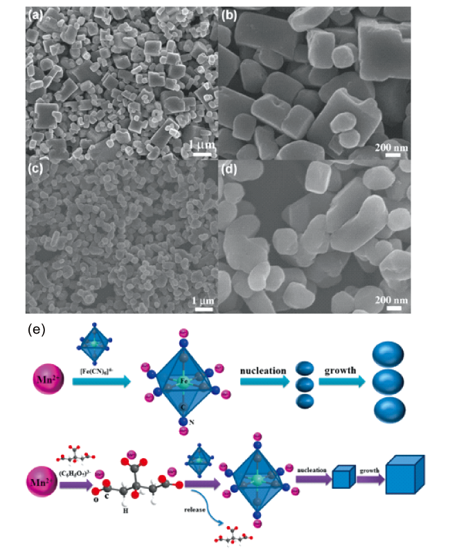
3.1 Chelating agent assisted method
3.2 Increase Na+concentration
3.3 Element doping
3.4 Inactive layer coating
3.5 Conductive agent composite technology
3.6 Self-assembly
3.7 Other modification methods
4 Conclusion and outlook

Qingping Li , Tao Li , Chenchen Shao , Wei Liu . Modification of Cathode Materials for Prussian Blue-Based Sodium-Ion Batteries[J]. Progress in Chemistry, 2023 , 35(7) : 1053 -1064 . DOI: 10.7536/PC221116
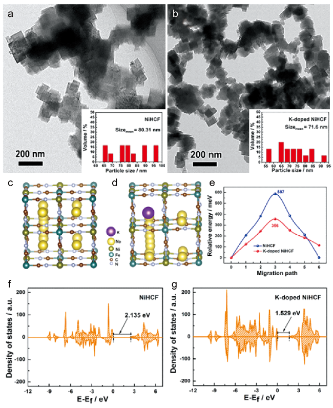
图4 (a, b) NiHCF和K-NiHCF的透射电镜(TEM)图像;(c~e) Na+的优化迁移路径和相应的NiHCF和K-NiHCF的能垒分布;(f,j) NiHCF和K-NiHCF的总态密度(TDOS)图像[52]Fig.4 (a,b) TEM images of NiHCF and K-doped NiHCF, respectively; (c~e) The optimized migration paths of Na+ ions and the corresponding energy barrier profiles for NiHCF and K-doped NiHCF species; (f, g) the total density of state (TDOS) patterns of NiHCF and K-doped NiHCF[52] |
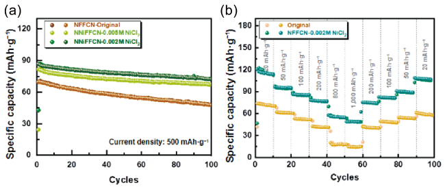
图6 (a) NFFCN-Original, NFFCN-0.005M NiCl2, NFFCN-0.002M NiCl2 在500 mA·g-1的循环稳定性;(b) NFFCN-Original和NFFCN-0.002M NiCl2的倍率性能[55]Fig.6 (a) the cycling performance of NFFCN-Original, NFFCN-0.005M NiCl2, NFFCN-0.002M NiCl2 at 500 mA·g-1; (b) rate performance comparison of NFFCN-Original and NFFCN-0.002M NiCl2[55] |
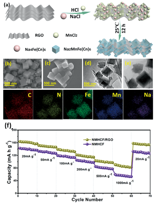
图8 (a)高度均匀的NMHCF/RGO的合成工艺;(b) NMHCF的SEM图像;(c) NMHCF/RGO的SEM图像;(d) NMHCF/RGO的TEM图像;(e) NMHCF/RGO的元素分布图像;(f) NMHCF和NMHCF/RGO的倍率性能[59]Fig.8 (a) Synthesis process of highly uniform NMHCF/RGO. SEM images of (b) NMHCF and (c) NMHCF/RGO samples; TEM images of (d) NMHCF/RGO; (e) Elemental mapping images of the NMHCF/RGO; (f) Rate performances of NMHCF/RGO and NMHCF[59] |
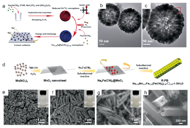
图10 (a) Na1.58Fe[Fe(CN)6]0.92纳米空心球的合成过程和Na1.58Fe[Fe(CN)6]0.92纳米球电极在钠离子电池中的放电机理的化学图解[70];(b,c) Na1.58Fe[Fe(CN)6]0.92纳米空心球的TEM图像[70];(d) 制备多级中空棒状普鲁士蓝的合成方法[71]; (e~g) PW-HN在1 h、12 h、24 h的场发射扫描电镜(FESEM)图像[72]; (h) PW-HN的横截面FESEM图像[72]Fig.10 (a) Schematic illustration of the synthesis procedure for Na1.58Fe[Fe(CN)6]0.92 hollow nanospheres and the discharge mechanism of Na1.58Fe[Fe(CN)6]0.92 nanosphere electrodes in sodium-ion batteries.[70].; (b,c) TEM images of hollow Na1.58Fe[Fe(CN)6]0.92[70] ; (d) Synthetic procedures for the preparation of hierarchical hollow rod-like Prussian blue[71]; (e~g) Time-dependent FESEM images of PW-HN after the reaction time of 1 h, 12 h, 24 h[72]; (h) Cross-section FESEM images of PW-HN[72] |
表1 通过不同方法改性的PBAs的性能对比Table 1 Performance comparison of PBAs modified by different methods |
| PBAs | Modification method | Discharge specific capacity | Cyclic stability | Rate capability | ref |
|---|---|---|---|---|---|
| Na1.56Mn[Fe(CN)6]0.86□0.14·1.2H2O | Chelating agent assisted | 133 mAh·g-1 at 15 mA·g-1 | 80% after 100 cycles at 150 mA·g-1 | 89 mAh·g-1 at 300 mA·g-1 | 22 |
| Na1.80Mn[Fe(CN)6]0.98·1.76H2O | Chelating agent assisted | 144 mAh·g-1 at 0.1 C | 72.7% after 2100 cycles at 1 C | 86.6 mAh·g-1 at 10 C | 25 |
| Na2.01Ni[Fe(CN)6]0.85·1.61H2O | Chelating agent assisted | 86.3 mAh·g-1 at 0.2C | 90.4% after 800 cycles at 0.5 C | 74.9 mAh·g-1 at 10 C | 32 |
| Na2.2Ni[Fe(CN)6]0.8□0.2·2.5H2O | Chelating agent assisted | 76.4 mAh·g-1 at 0.2 C | 90.4% after 16 000 cycles at 20 C | 71.9 mAh·g-1 at 10 C | 33 |
| Na1.92Mn[Fe(CN)6]0.98·1.38H2O | Chelating agent assisted | 152.8 mAh·g-1 at 10 mA·g-1 | 82 % after 500 cycles at 100 mA·g-1 | 110.3 mAh·g-1 at 1 A·g-1 | 34 |
| Na1.48Ni[Fe(CN)6]0.89·2.87H2O | Chelating agent assisted | 85.7 mAh·g-1 at 0.1 C | 78% after 1200 cycles at 50 C | 66.2 mAh·g-1 at 50 C | 35 |
| Na0.22Ni[Fe(CN)6]0.76·3.67H2O | Chelating agent assisted | 78 mAh·g-1 at 17 mA·g-1 | 97.3% after 1200 cycles at 300 mAh·g-1 | 57.5 mAh·g-1 at 4.25 A·g-1 | 36 |
| Na1.87Co[Fe(CN)6]0.98·2.2H2O | Increase Na+ concentration | 151 mAh·g-1 at 20 mA·g-1 | 85.2% after 100 cycles at 20 mA·g-1 | 115 mAh·g-1 at 400 mA·g-1 | 26 |
| Na1.96Mn[Mn(CN)6]0.99□0.01·2H2O | Increase Na+ concentration | 209 mAh·g-1 at 0.2 C | 75% after 100 cycles at 2 C | - | 39 |
| NaxFe[Fe(CN)6]y·nH2O | Increase Na+ concentration | 130 mAh·g-1 at 0.2 C | - | 110 mAh·g-1 at 5 C | 40 |
| Na1.52Ni0.24Fe0.76[Fe(CN)6]0.95·3.06H2O | Element doping | 105.9 mAh·g-1 at 20 mA·g-1 | 73.1% after 1000 cycles at 1 A·g-1 | 55.5 mAh·g-1 at 2 A·g-1 | 44 |
| Na2Cu0.6Ni0.4[Fe(CN)6] | Element doping | 62 mAh·g-1 at 0.5 C | 96% after 1000 cycles at 10 C | 56 mAh·g-1 at 10 C | 45 |
| Na1.68Ni0.14Co0.86[Fe(CN)6]0.84 | Element doping | 145 mAh·g-1 at 15 mA·g-1 | 90% after 100 cycles at 750 mA·g-1 | 110 mAh·g-1 at 750 mA·g-1 | 46 |
| Na1.85Ni0.40Co0.31Fe0.29 [Fe(CN)6]0.97·2.5H2O | Element doping | 120.4 mAh·g-1 at 20 mA·g-1 | 95.6% after 1000 cycles at 2 A·g-1 | 80 mA·h-1 at 2 A·g-1 | 48 |
| Na1.61K0.13Ni[Fe(CN)6]0.89· 1.48H2O | Element doping | 87.1 mAh·g-1 at 10 mA·g-1 | 86.1% after 500 cycles at 800 mA·g-1 | 68.2 mAh·g-1 at 200 mA·g-1 | 52 |
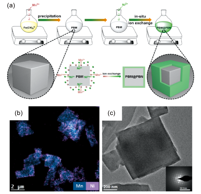
| Mn[Fe(CN)6]@Ni[Fe(CN)6] | Inactive layer coating | 126.9 mAh·g-1 at 0.5 C | 74.3% after 800 cycles at 1 C | 87.2 mAh·g-1 at 10 C | 54 |
| NNiFCN@NFFCN | Inactive layer coating | 113.67 mAh·g-1 at 20 mA·g-1 | 83.18 after 100 cycles at 500 mA·g-1 | 82.9 mAh·g-1 at 500 mA·g-1 | 55 |
| FeHCF@CuHCF | Inactive layer coating | 89 mAh·g-1 at 50 mA·g-1 | 80.6 after 1000 cycles at 50 mA·g-1 | 51.9 mAh·g-1 at 1.6 A g-1 | 56 |
| NaMn[Fe(CN)6]/RGO | Conductive agent composite technology | 161 mAh·g-1 at 20 mA·g-1 | - | 90 mAh·g-1 at 1 A·g-1 | 59 |
| NaxFe[Fe(CN)6]/CNT | Conductive agent composite technology | 142 mAh·g-1 at 0.1 C at -25℃ | 86% after 1000 cycles at 2.4 C at -25℃ | 88.4 mA·h g-1 at 2.4 C at -25℃ | 63 |
| NaxFe[Fe(CN)6]@PANI | Conductive agent composite technology | 108.3 mAh·g-1 at 100 mA·g-1 | 93.4% after 500 cycles at 100 mA·g-1 | 90.3 mAh·g-1 at 2 A·g-1 | 65 |
| Na2Fe[Fe(CN)6]@PANI | Conductive agent composite technology | 149.9 mAh·g-1 at 1 C | 62.7% after 500 cycles at 1 C | 125.6 mAh·g-1 at 20 C | 66 |
| Na1.58Fe[Fe(CN)6]0.92 | Self-assembly | 142 mAh·g-1 at 0.1 C | 90% after 800 cycles at 2 C | 101 mAh·g-1 at 5 C | 70 |
| Na0.99Mn0.37Fe0.63[Fe(CN)6]0.96·1.36H2O | Self-assembly | 117.3 mAh·g-1 at 1 C | 98.5% after 200 cycles at 1 C | 92.4 mAh·g-1 at 20 C | 71 |
| Na3.1Fe4[Fe(CN)6]3 | Self-assembly | 115 mAh·g-1 at 2 C | 65% after 10 000 cycles at 10 C | 83 mAh·g-1 at 50 C | 72 |
| [1] |
|
| [2] |
|
| [3] |
|
| [4] |
|
| [5] |
|
| [6] |
|
| [7] |
|
| [8] |
|
| [9] |
|
| [10] |
|
| [11] |
|
| [12] |
|
| [13] |
|
| [14] |
|
| [15] |
|
| [16] |
|
| [17] |
|
| [18] |
|
| [19] |
|
| [20] |
|
| [21] |
|
| [22] |
|
| [23] |
|
| [24] |
|
| [25] |
|
| [26] |
|
| [27] |
|
| [28] |
|
| [29] |
|
| [30] |
|
| [31] |
|
| [32] |
|
| [33] |
|
| [34] |
|
| [35] |
|
| [36] |
|
| [37] |
|
| [38] |
|
| [39] |
|
| [40] |
|
| [41] |
|
| [42] |
|
| [43] |
|
| [44] |
|
| [45] |
|
| [46] |
|
| [47] |
|
| [48] |
|
| [49] |
|
| [50] |
|
| [51] |
|
| [52] |
|
| [53] |
|
| [54] |
|
| [55] |
|
| [56] |
|
| [57] |
|
| [58] |
|
| [59] |
|
| [60] |
|
| [61] |
|
| [62] |
|
| [63] |
|
| [64] |
|
| [65] |
|
| [66] |
|
| [67] |
|
| [68] |
|
| [69] |
|
| [70] |
|
| [71] |
|
| [72] |
|
| [73] |
|
| [74] |
|
| [75] |
|
/
| 〈 |
|
〉 |