Home Journals Progress in Chemistry
Progress in Chemistry

Abbreviation (ISO4): Prog Chem      Editor in chief: Jincai ZHAO

About  /  Aim & scope  /  Editorial board  /  Indexed  /  Contact  / 
Review

Preparation and Application of Functional Polymer-Based Electromagnetic Shielding Materials

  • Wenbo Zhang , 1, * ,
  • Jianing Wang 1 ,
  • Linfeng Wei 2 ,
  • Hua Jin 3 ,
  • Yan Bao 4 ,
  • Jianzhong Ma 4
Expand
  • 1 College of Chemistry and Chemical Engineering, Shaanxi Collaborative Innovation Center of Industrial Auxiliary Chemistry and Technology, Shaanxi University of Science & Technology,Xi’an 710021, China
  • 2 Xi’an Rare Metal Materials Institute Co. Ltd,Xi’an 710016, China
  • 3 School of Design and Creativity, Wenzhou Polytechnic University,Wenzhou 325000, China
  • 4 College of Bioresources Chemical and Materials Engineering (College of Flexible Electronics), Shaanxi University of Science and Technology,Xi’an 710021, China
* Corresponding author e-mail:

Received date: 2022-11-24

  Revised date: 2023-02-28

  Online published: 2023-03-30

Supported by

National Natural Science Foundation of China(21908141)

National Natural Science Foundation of China(52073164)

Key Research and Development Program of Shaanxi Province(2019GY-171)

Zhejiang Provincial Basic Public Welfare Research Plan Project(LGG21E030003)

Abstract

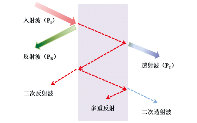
With the rapid development of high-power electronic equipment and electronic communication technology such as the emerging 5G mobile network communication technology, the development of high-performance electromagnetic interference shielding materials has become a desideratum. Polymer-based electromagnetic shielding materials (PEMSM) have been widely applied due to their advantages of lightweight, machinability, and adjustable conductivity. The increasingly complex application environment and operating conditions put forward higher requirements for the functionality of PEMSM. This paper firstly discusses the key concepts and loss mechanism of electromagnetic shielding (reflection, absorption, and multiple reflections), and then summarizes the current structural design of electromagnetic shielding composites including homogeneous structure, segregation structure, porous structure, and layered structure. The process of homogeneous structure is simple, and segregation structure can reduce the conductivity percolation threshold of materials. The porous structure is helpful for electromagnetic waves reflection and absorption, and the layered structure can make electromagnetic wave reflect inside the material many times. The research progress of PEMSM with the functions such as durability, superhydrophobicity, antibacterial property, Joule heating property, etc. is introduced in detail. Finally, the development of PEMSM is prospected.

Contents

1 Introduction

2 Mechanism of EMI Shielding

3 Structural designs of polymer-based electromagnetic shielding materials

3.1 Homogeneous structure

3.2 Segregation structure

3.3 Porous structure

3.4 Layered structure

4 Functional polymer-based electromagnetic shielding materials

4.1 Durability

4.2 Superhydrophobicity

4.3 Antibacterial property

4.4 Joule heating property

4.5 Others

5 Conclusion and outlook

Cite this article

Wenbo Zhang , Jianing Wang , Linfeng Wei , Hua Jin , Yan Bao , Jianzhong Ma . Preparation and Application of Functional Polymer-Based Electromagnetic Shielding Materials[J]. Progress in Chemistry, 2023 , 35(7) : 1065 -1076 . DOI: 10.7536/PC221121

1 Introduction

Electronic devices such as mobile phones, Bluetooth and wireless chargers are more and more widely used in daily life, and various communication devices also play an important role in industry, aerospace and other fields[1][2,3]. However, electronic equipment will produce electromagnetic interference (EMI) to the outside world during operation, which not only affects the normal operation of other electronic equipment, but also increases the risk of headache, depression, immunodeficiency and other diseases for related workers[4~6]. Therefore, there is an urgent need for efficient electromagnetic shielding materials to attenuate electromagnetic waves to protect the normal operation of electronic equipment and human health.
Polymer-based electromagnetic shielding materials (PEMSM) mainly shield electromagnetic waves in the form of reflection attenuation. They are conductive polymer composites (CPCs) prepared by insulating polymer matrix and filled with conductive fillers, in which conductive fillers play an important role, such as carbon black (CB), carbon nanofibers, carbon nanotubes (CNT), graphene and its derivatives (GNS), carbon fibers and MXene[7,8][9][10][11~13][14~17][18][19]. Compared with metal electromagnetic shielding materials, PEMSM has the characteristics of low density, corrosion resistance and good machinability[20,21]. The electromagnetic shielding performance of materials has an important relationship with conductive fillers. Usually, the ability to attenuate electromagnetic waves is improved by adjusting the amount and type of conductive fillers to increase the conductivity. In addition, the structure of the material is equally important. The attenuation mechanism in the shielding process can be adjusted through the structure design. A perfect conductive network is a prerequisite for obtaining excellent electromagnetic shielding effectiveness. Effective multiple interface reflection and scattering, as well as the hysteresis loss of the material itself, are important factors for regulating EMI SE. Therefore, how to improve the electromagnetic shielding performance of PEMSM through efficient structure design has become a current research focus[22]. With the wide use of PEMSM, it is also facing increasingly complex application environment and use requirements, such as long-term use performance such as wear resistance, super-hydrophobic performance in humid and rainy environment, antibacterial performance in biological pollution environment, and electric heating performance in cold environment.
Based on this, the key concepts and loss mechanisms of electromagnetic shielding are discussed in this paper. The research progress of PEMSM with different structures and functional PEMSM is introduced in detail. The influence of structure on the electromagnetic shielding effectiveness of PEMSM and the key to realize the function are described. Finally, the development prospect of PEMSM is prospected.

2 Electromagnetic shielding mechanism

Electromagnetic shielding is to use the shielding body to reflect and attenuate the electromagnetic wave so that it can not enter the shielding area. Among the eddy current effect theory, electromagnetic field theory and transmission line theory, the transmission line theory is highly recognized, that is, the electromagnetic wave passing through the shielding material will be affected by three different shielding mechanisms, including reflection, absorption and multiple reflection[23~25]. When an electromagnetic wave is incident on the surface of the shielding material, it is reflected due to the impedance mismatch between the shielding material and the external free space. When the unreflected electromagnetic wave enters the shielding material, it will be attenuated in the form of dielectric loss, magnetic loss and conduction loss[26~31]. In addition, when the unconsumed electromagnetic wave inside the material reaches another surface of the material, it will encounter the interface between the material and the air again and return to the inside of the material again. This reflection is called multiple reflection. The residual electromagnetic wave will pass through the shielding material and become a transmitted wave[32,33][34~36][37,38]. The electromagnetic shielding mechanism based on the transmission line theory is shown in Fig. 1.
图1 基于传输线理论的电磁屏蔽机制示意图

Fig.1 Schematic diagram of EMI shielding mechanism based on transmission line theory

The attenuation or loss of electromagnetic waves is one of the key indicators to evaluate the ability of materials to shield electromagnetic waves. It can be qualitatively described as the difference in the intensity of the electromagnetic wave before and after shielding. The electromagnetic shielding mechanism mainly includes reflection and absorption, which can be determined by the power coefficient. The power coefficient is a general term for the reflection coefficient (R), absorption coefficient (A), and transmission coefficient (T)[39]. The definitions and relationship formulas of R, A and T are as follows:
R = P R e f P i n , T = P o u t P i n , A = 1 - R - T
Where PRef, Pout, and Pin represent the power reflected by the upper and lower surfaces of the material, the power of the output material, and the power of the input material, respectively.
EMI Shielding Effectiveness (EMI SE, unit: dB) can be used to quantitatively evaluate the ability of materials to shield electromagnetic waves. The higher the EMI SE, the stronger the Shielding effect[40]. It is defined as the ratio of the electric field intensity (E), magnetic field intensity (H) or power (P) of the electromagnetic wave before entering the shielding material to that after passing through the shielding material, which is expressed by formula (2):
S E T ( d B ) = 10 l g P t P i = 20 l g E t E i = 20 l g H t H i
Where Pi, Pt are the power of incident and transmitted electromagnetic waves, respectively,Ei, Et are the electric field strength of the incident and transmitted electromagnetic waves, respectively, and Hi, Ht are the magnetic field strength of the incident and transmitted electromagnetic waves, respectively.
To quantitatively describe the shielding performance, the EMI SE is defined as the sum of three shielding mechanisms of reflection loss (SER), absorption loss (SEA) and multiple reflection loss (SEM) according to the Schelkunoff formula:
S E ( d B ) = S E R + S E A + S E M
SER, SEA and SEM can be further expressed as follows:
S E R = 168.2 + 10 l g σ r f μ r
S E A = 131.43 t f μ r σ r
S E M = 20 l g 1 - e - 2 t δ = 20 l g 1 - 10 S E A 10
In the above formula, σ r represents the relative conductivity, μ r represents the relative permeability, f represents the electromagnetic wave frequency (Hz), t represents the thickness of the shielding material (m), δ represents the skin depth (m), and R represents the distance from the radiation source to the shielding material (m). For electrically thick materials, the electromagnetic wave travels a long path inside the material due to its thickness. When it reaches the lower surface of the material for the first time, a lot of energy has been consumed, so the energy reflected or transmitted through the lower surface for the second time is negligible, so the SEM can be ignored. On the contrary, for electrically thin materials, the SEM can not be ignored. When the SEA≥10 dB of the shielding material, the SEM can be neglected. It can be seen from the above formula that the conductivity of the shielding material is positively correlated with SEA and SER. However, the permeability of shielding materials is positively correlated with SEA and negatively correlated with SER. Therefore, increasing the conductivity of shielding materials and introducing magnetic loss are beneficial to improve the shielding effectiveness of electromagnetic shielding materials.
In addition to the factors affecting the performance of electromagnetic shielding, the analysis of shielding mechanism is another important content of electromagnetic shielding research. It can be seen from equation (1) that if A > R, more incident electromagnetic waves are attenuated by absorption inside the material, and conversely, a higher R coefficient indicates that most of the incident electromagnetic waves are reflected. The EMI SE consists of SER, SEA, and SET, which can be calculated by the scattering parameters (S-parameters) measured by a vector network analyzer using the following equation:[41~43]
S E R = 10 l g 1 1 - R = 10 l g 1 1 - | S 11 | 2 ,   R = | S 11 | 2 = | S 22 | 2
S E A = 10 l g 1 - R T = 10 l g 1 - | S 11 | 2 | S 21 | 2 , T = | S 21 | 2 = | S 12 | 2
S E T = S E R + S E A = - 10 l g T
Where T, R, and A are the transmission power coefficient, reflection power coefficient, and absorption power coefficient of the electromagnetic shielding material. Some researchers believe that if SEA>SER, the shielding mechanism should be absorption-dominated shielding. Pure 0000016 with a thickness of 8 μm was reported to have SET, SEA, and SER values of approximately 58, 35, and 23 dB, respectively, corresponding to electromagnetic shielding power coefficients of T = 0.0000016, A = 0.005, and R = 0.995[44]. Although SEA>SER, A < R, the shielding mechanism should be reflection-dominated shielding because 99.5% of the power is reflected and only 0.5% is absorbed by the shielding material. Therefore, it is incorrect to compare the values of SEA and SER to directly determine the shielding mechanism.
Materials that meet common commercial electromagnetic shielding requirements (> 20 dB) can be classified according to their primary shielding mechanism[45]. Materials that provide more than 50% absorption of incident electromagnetic waves can be classified as absorption-dominated shielding materials, and vice versa. As an absorption-dominated shielding material, its SER value should be lower than 3.0103 dB, which is calculated from Equation (7). However, this does not mean that the shielding mechanism will be absorption-dominated shielding when SER<3.0103 dB, because the relationship between R and A varies with T[46,47].

3 Structure Design of Polymer Matrix Electromagnetic Shielding Composites

Based on Schelkunoff's theory of electromagnetic wave interface conduction, improving the reflection loss and absorption loss ability of electromagnetic shielding materials is an important way to achieve high shielding performance. In addition to the exploration of efficient fillers, the structural design of PEMSM is particularly important. Through the structural design, the attenuation mechanism in the shielding process can be adjusted, and the electromagnetic shielding performance can be enhanced and regulated according to different shielding requirements, which increases the controllability of the electromagnetic shielding material. Therefore, it has become a new research focus to obtain efficient EMI SE by regulating the structure of composites[48~59]. According to the designed structure, PEMSM can be divided into homogeneous structure, isolated structure, porous structure and layered structure (as shown in TOC diagram)[60][61][62][63]. Among them, the homogeneous structure has a simple process flow; The isolation structure can effectively reduce the percolation threshold of the material; The porous structure is beneficial to the multiple reflection and absorption of electromagnetic waves; The layered structure can improve the impedance matching of the material and effectively reduce the problem of secondary electromagnetic wave pollution.

3.1 Homogeneous structure

Homogeneous structure is to distribute the filler uniformly in the composite and build a conductive network to obtain electromagnetic shielding properties. The commonly used preparation methods include in-situ polymerization, solution blending and melt blending[64].
In-situ polymerization is to form conductive composites by adding initiator to the mixture of conductive filler and monomer to initiate the polymerization of monomer. For example, Patil et al. Prepared conductive polymer composites by in situ polymerization of pyrrole in the presence of Ba0.6Sr0.4Fe12O19 particles[65]. In the structure of hexaferrite, positive and negative ions of different valences are separated at different bond lengths, causing dipole polarization; In polycrystalline ferrites, low-resistance grains are separated by high-resistance grain boundaries, which produce interfacial polarization; Multiple polarizations enhance the electromagnetic shielding properties of the material. Zhang et al. Introduced polyaniline modified graphene oxide (PANI-g-GO) and multi-walled carbon nanotubes (MWCNT) in the in-situ polymerization of polyimide (PI), and prepared PI electromagnetic shielding composite (PPIC) by thermally assisted non-solvent induced phase separation (TNIPS)[66]. It is found that the mixed filler can form an effective conductive network in the PI matrix, so the electromagnetic shielding performance is improved. This method does not have a high shear force, so the surface structure of the filler is not easily destroyed. However, conductive fillers often require surface modification, which can compromise the physical and chemical properties of the filler.
The solution blending method is to prepare PEMSM by dispersing the conductive filler in the polymer matrix using a suitable solvent and then removing the solvent. In the solution mixing system with lower viscosity, the polymer and conductive filler can be uniformly mixed to ensure the formation of conductive pathways inside the final composite. Wei et al. Immobilized polydopamine (PDA) on the surface of GNS and blended it with aqueous anionic styrene-acrylic latex to prepare composites[67]. The pH value of the film is adjusted to 6.4, at this time, the phenolic hydroxyl of the polydopamine is ionized to be negatively charged, and is dispersed and not agglomerated with the anionic styrene-acrylic emulsion under the action of electrostatic repulsion, the pH value is reduced along with the evaporation of water in the film forming process, and the ionized phenolic hydroxyl is protonated again and forms a hydrogen bond with the ester carbonyl in the polyacrylate,Hydrogen bonding enhances and dominates the interfacial bonding, which not only realizes the stable dispersion of the filler during blending, but also enhances the interfacial interaction during film formation, and the shielding performance is further improved. The EMI SE of the composite with 20 wt% filler content is 58 dB at a thickness of 0. 6 mm. In order to ensure the stability of the filler in solution, it can be modified. Chen et al. Deposited nickel particles on the surface of graphite nanosheets, prepared high conductive GnPs @ Ni core-shell structure mixed filler by electroplating method, and prepared high thermal conductive GnPs @ Ni/PPSU composite by solution blending and hot pressing method with modified GnPs @ Ni and polyphenylsulfone (as shown in Figure 2)[68]. The results show that the maximum EMI SE of the composite can reach 42. 9 dB at 40 wt% filler loading. The solution blending method can significantly reduce the viscosity of the composite system, thereby improving the dispersion of the filler in the polymer matrix. However, this method generally requires the addition of a large amount of organic solvents such as toluene, which will cause problems such as solvent residues and environmental pollution, and the incomplete subsequent treatment of solvents will shorten the service life of materials.
图2 共混法制备GnPs@Ni/PPSU复合材料的示意图[68]

Fig.2 Schematic diagrams of preparation of GnPs@Ni/PPSU composite by solution blending[68]

The melt-blending method obtains a viscous melt by melting the polymer, and then uses high shear forces to complete the dispersion of the filler. Bhawal et al. Prepared in-situ reduced graphene oxide (IrGO) by in-situ melt blending of ethylene methacrylate (EMA) and graphene oxide (GO), and introduced it into EMA matrix and molded it. A continuous conductive network could be constructed with 5 wt% IrGO, and the shielding effectiveness was 30 dB at 8.2 ~ 12.4 GHz[69]. Sharika et al. Introduced MWCNTs into polypropylene (PP) and natural rubber (NR) blends by melt blending[70]. Conductive pathways can be established in insulating polymer matrices by efficient dispersion of conductive nanoparticles in the host matrix. High-aspect-ratio MWCNTs can reduce the percolation threshold many times because they are able to form conductive pathways in the matrix at a relatively low ratio. Compared with the solution blending method, the melt blending method has the advantages of simple operation, low cost and no third-party solvent. However, the shear force in melt blending will shorten the length of rod-like fillers, which is not conducive to the construction of conductive network, resulting in the decline of electromagnetic shielding performance.
Materials with homogeneous structure are widely used in commercial fields because of their simple processing process and short cycle. However, the filler content is often high, and it is easy to agglomerate, which has a negative impact on the properties of the composite.

3.2 Isolation structure

For the isolated PEMSM, the conductive filler is isolated at the edge of the polymer particles by the volume exclusion effect, which can significantly improve the construction efficiency of the conductive network in the polymer matrix, thus effectively reducing the percolation threshold of the material, so that the material can obtain ideal conductivity and electromagnetic shielding performance with less filler addition[71]. At present, there are two main methods to construct the isolation structure: one is to load the conductive filler on the polymer particles in advance, and prepare it by compression molding and other processes. Wang et al. Mechanically mixed CNT and polyurethane (PUDA) by a ball mill to form CNT-coated PUDA composite particles, and formed CNT @ PUDA composites with isolated structure by hot pressing[72]. It was found that the CNTs were selectively distributed between the interfaces of the PUDA region and constructed a conductive network, which endowed the composite with excellent electromagnetic shielding properties. The other is to prepare a three-dimensional interconnected network structure first, and then fill the conductive filler into the pores. Wang et al. Used 3D printing technology to prepare a three-dimensional interconnected network framework of polylactic acid (PLA), and the highly conductive carbon nanotubes coated on the PLA scaffold by dip coating method were converted into a conductive network after compression molding, and the EMI SE of the composite changed with the adjustment of CNT content[73]. Although the isolated structure has outstanding advantages in reducing the percolation threshold, the mechanical properties of the composite are reduced to different degrees due to the selective distribution of fillers on the interface of polymer particles. Therefore, while maintaining the excellent electromagnetic shielding performance of isolated PEMSM, further optimization of mechanical properties and manufacturing cost is the key to achieve large-scale applications.

3.3 Porous structure

The porous PEMSM takes the polymer matrix as the supporting skeleton, which is then modified or loaded with conductive fillers. Foaming (chemical foaming and physical foaming) and freeze-drying are the common methods to prepare porous structures.
Chemical foaming method refers to the mixing of foaming agents (azo compounds, sulfonyl hydrazide compounds, nitroso compounds, etc.) into polymer matrix composites, which can decompose during heating to produce gases to foam the composites. For example, Eswaraiah et al. Prepared a fG/PVDF composite with porous structure by chemical foaming method using functionalized graphene (fG) as conductive filler, polyvinylidene fluoride (PVDF) as polymer matrix, and azobisisobutyronitrile (AIBN) as foaming agent. When the fG content was 0.5 wt%, the EMI SE of the fG/PVDF composite was 20 dB at 8 – 12 GHz[74]. Physical foaming method refers to the nucleation, growth and stabilization of gases generated by supercritical fluids (SCF)(CO2, N2, butane, pentane, etc.) in the thermodynamically unstable state, so as to realize the foaming of PEMSM[75]. Hamidinejad et al. Prepared high density polyethylene (HDPE) -graphene nanosheet (GnP) composite foams by SCF treatment and physical foaming[76]. The microporous structure gives it higher conductivity, dielectric constant, and EMI SE. The above study shows that the foaming method for preparing electromagnetic shielding composites is suitable for a variety of polymer matrices, and the conductive filler can be dispersed again during the foaming process. However, the improvement of EMI SE of PEMSM by a single foaming technique is limited. In practical applications, it is necessary to combine other methods to further improve the electromagnetic shielding performance of composites.
In addition, freeze-drying technology can also control the electromagnetic shielding performance of composites, mainly by controlling the directional growth of ice crystals in the freezing process to achieve the orientation of cells, thereby adjusting the conductive network structure in electromagnetic shielding materials[77,78]. For example, Zhao et al. prepared MXene/graphene aerogel foam by freeze-drying technology (as shown in Fig. 3 (a)). The high conductive network endows the composite with excellent electromagnetic shielding performance under very low load, and the aerogel foam shows electromagnetic shielding performance of more than 50 dB[79]. Zeng et al. Prepared CNT/waterborne polyurethane composite foam with vertically oriented cell structure by vacuum freeze-drying using gradient-grown ice crystals as templates, and the density of the composite foam was as low as 20 mg/cm3, and the specific electromagnetic shielding effectiveness reached 1148 dB·cm3·g-1[80]. Based on the development of freeze-drying technology, the two-way freeze-drying technology further improves the orderly construction of materials on the micro-nano scale[81]. Sambyal et al. prepared MXene/MWCNT aerogel (as shown in Fig. 3 (B)) by using bidirectional freeze-drying technology. The highly ordered multi-scale construction and the introduction of multiple interfaces make the electromagnetic shielding effectiveness of the material as high as 103.9 dB[82]. The combination of freeze-drying technology and the special network structure design of electromagnetic shielding composites can not only effectively solve the problem of non-uniform shielding network in porous structure, but also endow the porous structure with microwave absorbing characteristics and achieve ultra-light, ultra-tough and other ultra-strong mechanical properties through the structural advantages of cell orientation.
图3 (a) Ti3C2Tx MXene/RGO泡沫结构电磁屏蔽复合材料的制备过程[79]。(b) 双向冷冻方法制备Ti3C2Tx/CNT混合气凝胶[82]

Fig.3 (a) Preparation of Ti3C2Tx MXene/RGO foam structure electromagnetic shielding composite[79]. (b) Ti3C2Tx/CNT hybrid aerogel fabricated by bidirectional freezing method[82]

Compared with traditional materials, porous PEMSM has the advantages of low cost, good toughness and low density. The construction of porous structure in the composite is conducive to reducing the dielectric constant of the composite, making the surface impedance of the material close to or consistent with the free space impedance, contributing to the multiple reflection and absorption of electromagnetic waves, and further improving the electromagnetic shielding performance of the composite. However, the decomposition of chemical foaming agents requires temperature, the process is more complex, and some foaming agents are easy to produce toxic gases, which does not meet the requirements of environmental protection.

3.4 Layered structure

The PEMSM with layered structure can make the electromagnetic wave reflect many times in the composite, and the impedance mismatch between different conductive layers further induces the interface polarization, which greatly improves the electromagnetic shielding performance. The electromagnetic wave is incident into the material from the absorbing layer with good impedance matching, resulting in absorbing dissipation, and is reflected back to the absorbing layer by the highly conductive reflective layer after passing through the absorbing layer, resulting in secondary absorbing dissipation. The layered structure can be constructed by stacking different lamellae alternately to achieve a conductive network perpendicular to the stacking direction. At present, the preparation methods of layered structural materials include vacuum filtration, curing and lamination.
The vacuum filtration method refers to the preparation of PEMSM by removing the solvent from the mixed solution of conductive filler and polymer matrix under a pressure difference. The film prepared by vacuum filtration method has obvious layered structure, which can effectively reflect electromagnetic waves many times. Zhou et al. Used cellulose nanofibers (CNF) and MXene as raw materials to prepare multilayer CNF @ MXene films by alternating vacuum filtration method (Fig. 4 (a))[83]. The EMI SE of the CNF @ MXene film with a thickness of 0.035 mm at X-band is about 40 dB, which is higher than that of the film with a uniform structure, and the main reason is that the alternating multilayer structure of the CNF @ MXene film increases the zigzag reflection mechanism of electromagnetic waves. Wang et al. Proposed to prepare flexible ultrathin Ti3C2Tx/Fe3O4@PANI composite film with sandwich structure by vacuum assisted filtration method[84]. The addition of Fe3O4@PANI significantly improves the electromagnetic shielding performance of MXene system, and the electromagnetic shielding performance of the composite film is 58. 8 dB. The existence of Fe3O4@PANI not only balances the impedance matching of MXene, but also increases the magnetic loss, heterointerface, surface defects, and effectively increases the dielectric loss. The thickness of the electromagnetic shielding film prepared by the vacuum filtration method is easy to control, and the utilization rate of raw materials is high. However, the area of the film is limited by the size of the device, and it takes a long time for the two-dimensional nanosheet-containing material to form a film by vacuum filtration.
The curing method refers to curing a mixed system containing a conductive filler and a polymer matrix in an appropriate mold to prepare a PEMSM. This method is relatively simple and widely used in practical production. In order to build a more complete conductive network inside the electromagnetic shielding film, the viscosity and curing time of the polymer matrix are the key to the process. Xu et al. Used Fe3O4@rGO and silver-coated tetragonal needle-like zinc oxide whiskers (T-ZnO/Ag) as fillers to prepare Fe3O4@rGO/T-ZnO/Ag/WPU films by solidification method (Fig. 4 (B))[85]. The EMI SE reaches 87.2 dB at X-band with a thickness of only 0.5 mm. Due to the difference in density between Fe3O4@rGO and t-ZnO/Ag, a gradient structure is automatically formed during film formation. The Fe3O4@rGO is uniformly distributed over the entire film thickness, forming an effective three-dimensional electromagnetic wave absorption network. T-ZnO/Ag is uniformly deposited on the bottom of the film, forming an effective two-dimensional electromagnetic wave reflection network. The electromagnetic wave path design of "absorbing-reflecting-absorbing" realizes the functional integration of high shielding effectiveness and high electromagnetic wave absorption under thin thickness. The above study shows that the film prepared by the solidification method is not limited by the equipment and can be produced on a large scale. The electromagnetic shielding film with gradient structure can be prepared by using the density difference of the conductive filler, so that the film has excellent electromagnetic wave absorption performance. However, the curing method also faces some problems, such as the curing process of the polymer matrix is time-consuming, and the interlayer of the film is not dense.
Lamination refers to the preparation of PEMSM by directly depositing conductive fillers on the surface of polymer matrix film through laser printing, high pressure spraying, sputtering deposition and other methods. Chen et al. Continuously constructed dense AgNW and MXene conductive grids on polyethylene terephthalate (PET) substrates using high-pressure air-assisted spraying technique (as shown in Fig. 4 (C))[86]. The EMI SE of the obtained film can reach 49 dB. Wei et al. used PVDF as the polymer matrix, CNT as the radar absorbing filler, and GNS as the conductive filler to prepare a PVDF/CNT/GNS composite material with a "radar absorbing-reflecting" double-layer structure with broadband absorption in the X-band by using a laminated hot-pressing technology, and its shielding effectiveness met the requirements of commercial shielding materials[87]. Although the lamination method can produce composite films rapidly and continuously, the bonding strength between the conductive filler network and the polymer matrix is not high, which easily leads to interfacial separation[88].
图4 (a) 交替多层CNF@MXene薄膜的制备过程[83]。(b)固化法制备rGO@Fe3O4/T-ZnO/Ag/WPU复合薄膜[85]。(c)MXene/AgNW薄膜制备示意图[86]

Fig.4 Preparation of (a) multilayer CNF@MXene films[83], (b) rGO@Fe3O4/T-ZnO/Ag/WPU composite films by curing method[85] and (c) transparent MXene/AgNW film[86]

4 Functional electromagnetic shielding composite material

Electromagnetic shielding composite materials only have a single shielding performance, which can not meet the various functional requirements in the application environment[89~93]. Multifunctionality is one of the main development directions of electromagnetic shielding materials. While pursuing the optimization of PEMSM shielding performance, it is necessary to cooperate with different application scenarios to obtain more performance, such as durability, superhydrophobicity, antibacterial and electrothermal.

4.1 Durability

With the development of wearable and foldable electronic products, electromagnetic shielding materials with excellent durability and reliability are urgently needed. Lin et al. Successfully prepared a flexible transparent electromagnetic shielding film based on silver nanofibers (AgNF) by roll-to-roll method at room temperature, and it has excellent electromagnetic shielding ability (76 dB, 100 μm).In addition, the flexibility and bending stability of the film were studied, and due to the specific structural advantages of one-dimensional materials and the inherent flexibility of metallic silver, the silver nanofiber film did not break despite bending by 180 ° (Fig. 5 (a))[94]. Liang et al. Prepared multifunctional flexible AgNWs/cellulose film by vacuum-assisted filtration and hot pressing, and obtained 101 dB electromagnetic shielding effect[95]. The hydrogen bonds between the AgNWs and cellulose sheets originate from their oxygen-containing functional groups (Fig. 5 (B)), which is beneficial to the formation of dense films with enhanced mechanical properties, and the excellent structural stiffness and mechanical flexibility enable the AgNWs/cellulose film to withstand complex deformations, and the EMI SE finally remains around 95 dB after 1500 cycles of bending. Wu et al. Prepared polydimethylsiloxane (PDMS) -coated MXene foam aerogel by directional freezing and freeze-drying, and the PDMS coating effectively endowed the 3D conductive network with excellent compressibility and durability, and its EMI SE was 48.2 dB after 500 compression-release cycles[96]. To sum up, electromagnetic shielding composites with durability and excellent stability can be obtained by selecting flexible conductive fillers, improving the force between fillers and polymer matrix, and selecting polymers with good flexibility, so as to realize their applications in wearable electronic devices, sensors and other specific fields.
图5 (a) 弯曲AgNF薄膜的扫描电镜图像[94]。(b) AgNWs和纤维素片之间的相互作用[95]

Fig.5 (a) SEM image of a bended AgNF film[94]. (b) Interaction between AgNWs and cellulose sheets[95].

4.2 Superhydrophobic

When PEMSM is used under harsh conditions such as moisture, acid and alkali, fillers such as nanoparticles and nanowires are easily oxidized or even corroded, and some polymers in PEMSM will also decompose and fail, thus adversely affecting the electromagnetic shielding performance[97~99][100,101]. Therefore, improving the hydrophobicity of electromagnetic shielding materials has become one of the research directions, and the superhydrophobic surface also has self-cleaning function, which is expected to improve the durability of materials. Li et al. Prepared a lightweight, flexible, and superhydrophobic polyacrylonitrile (PAN)@SiO2-Ag composite nanofiber membrane by electrospinning, and AgNPs were uniformly attached to the surface of PAN fiber through SiO2 nanoparticles, while perfluorodecanethiol (PTDT) was introduced to the surface of the fiber through Ag-S bonds to obtain superhydrophobicity, with a water contact angle of 156.99 °[102]. The combination of low surface energy and high surface roughness can effectively prevent the oxidation and corrosion of the Ag layer, thus ensuring the reliability of the composite film used as a shielding material under severe conditions. Zhou et al. Sandwiched a Ti3C2TxMXene conductive layer between a transparent polycarbonate (PC) substrate and superhydrophobic fumed silica (Hf-SiO2), and prepared a superhydrophobic and transparent electromagnetic shielding film by the combination of spraying technique and spinning method[103]. Air plasma treatment of the PC film increases its hydrophilicity by changing the surface roughness, and is beneficial to the wetting of MXene, which further forms a uniformly distributed conductive network. The Hf-SiO2 layer added on the top of the conductive layer finally makes the film super-hydrophobic. The (CA>150.7°),Hf-SiO2 coating not only gives the film excellent self-cleaning ability, but also prevents the oxidation of MXene. The material is waterproof and self-cleaning, and water droplets can absorb dust or pollutants on the surface, which has the potential to be applied to multi-functional wearable electronics and smart clothing. The construction of micro-nano rough structure on the surface of electromagnetic shielding materials and the introduction of low surface energy substances are the core to obtain superhydrophobic properties. The realization of this process combined with the selection and design of PEMSM matrix, filler and structure can effectively reduce the difficulty of the preparation of superhydrophobic electromagnetic shielding materials.

4.3 Antibacterial property

In addition to durability and other properties, electromagnetic shielding materials will also face a variety of complex environments, such as rain, stains, sweat, etc. Therefore, in the field of human wearable protection, electromagnetic shielding materials need to have excellent antibacterial properties to cope with the above complex environments. One of the commonly used methods is to use the antibacterial property of conductive fillers to achieve the antibacterial property of electromagnetic shielding materials, such fillers include silver, MXene and so on. Mu et al. Prepared a novel electroless silver-plated polyethylene terephthalate (PET) fabric by a two-step method of in situ polymerization and in situ reduction[104]. The EMI SE of silver-coated PET fabric is about 50 ~ 90 dB. Silver has natural antibacterial properties and is non-toxic to human cells. Antibacterial tests show that silver-plated fabrics exhibit 100% antibacterial activity against both Staphylococcus aureus and Escherichia coli. Zhu et al. Impregnated AgNWs into cellulose scaffolds (CS), and then hot-pressed and impregnated with PDMS. With the help of hydrogen bonding between AgNWs and cellulose fibers, a continuous conductive path was constructed in the channel of CS to obtain excellent electromagnetic shielding effect[105]. The Ag+ in AgNWs can fight against bacterial infectious diseases, and the introduction of PDMS layer can prevent the oxidation and shedding of AgNWs, and improve the hydrophobicity and antibacterial property of the composite membrane (Fig. 6 (a, B)). In addition, antibacterial materials can also be introduced into the system. Jiao et al. Prepared a core-shell composite composed of cotton-derived carbon fiber (CDCF) and nano-copper[106]. Oxidative free radicals can be produced by the interaction between nano-copper and the sulfhydryl group of the enzyme; Direct cell contact with CDCF affects bacterial membrane integrity, metabolic activity, and morphology[107]. The composite acquired antibacterial properties against E. coli and S. aureus (> 92%) as well as hydrophobicity (144 °) (as in Fig. 6 (C, d)). The application of this shielding material with antibacterial properties to wearable electronic devices can reduce the risk of bacterial transmission to human health.
图6 (a,b) d-AgNWs@CS-PDMS的水接触角和抗菌性[105]。(c,d)棉纤维、CDCFs和纳米Cu/CDCFs的抗菌性和水接触角[106]

Fig.6 Water contact angle and antibacterial activity of (a,b) d-AgNWs@CS-PDMS[105] and (c,d) cotton fibers, CDCFs and Cu/CDCFs[106]

4.4 Electrothermicity

Outdoor materials such as military tents, aircraft deicing devices, wearable electric heaters and smart textiles, in addition to ensuring normal electromagnetic shielding performance, also need to cope with the test of low temperature, so it is necessary to endow electromagnetic shielding materials with electrothermal performance[108][109]. Electrothermal material is a kind of functional resistor that converts electric energy into heat energy by Joule effect. Good conductivity is a necessary prerequisite for achieving efficient electromagnetic shielding performance and significant Joule heat capacity. At present, researchers mostly select efficient conductive fillers and construct conductive pathways to achieve synchronous realization of electromagnetic shielding and electrothermal performance. Guo et al. Fabricated PI composite films with high thermal conductivity and excellent electromagnetic shielding properties using a layered design and assembly strategy[110]. The top layer of the PI composite film is graphene oxide/expanded graphite (GO/EG), and its main function is thermal conduction and electromagnetic shielding. The main reason for the good electrical heating performance of the PI composite film is that its top layer is conductive, which generates heat due to the Joule effect (Fig. 7 (a)). Zhao et al. Prepared MXene/ANF @ FeNi composite film by in-situ growth and vacuum-assisted filtration method, magnetic FeNi nanoparticles can improve the EMI SE of the composite film through magnetic loss, and the efficient conductive network formed by MXene nanosheets can generate more Joule heat, which provides a basis for the electrothermal performance (as shown in Fig. 7 (B))[111]. Li et al. Prepared carbon nanofiber films (CNFFs) with an alternating multilayer structure by coating carbon nanofibers and silicone[112]. The films have excellent EMI SE (~ 100 dB, thickness as low as 0.6 mm) as well as good electrothermal properties, and this excellent performance is attributed to the high conductivity of CNFFs, which can generate Joule heating through inelastic collisions between electrons and phonons. To sum up, composite materials with excellent low pressure Joule thermal response and excellent operation stability are expected to be used in frontier industrial fields such as artificial intelligence, wearable equipment and controllable heating elements.
图7 (a) PI复合薄膜的制备示意图[110]。(b)MXene/ANF@FeNi复合薄膜的电热性能[111]

Fig.7 (a) Schematic diagram of PI composite film preparation[110]. (b) Joule heating property of MXene/ANF@FeNi film[111]

4.5 Other

At present, more and more functional electromagnetic shielding materials have been prepared and used in various fields by researchers, which has solved some thorny problems in special industries. In addition to the functions described above, some electromagnetic shielding materials also have the properties of oil-water separation, energy collection, and high light transmittance. Zhao et al. Prepared multifunctional magnetic carbon foams under the synergistic effect of nickel ion reduction and in situ growth of carbon nanotubes[113]. Under the stimulation of applied voltage, the increased absorption, interface polarization and multiple scattering caused by the accelerated transition of electrons in the porous three-dimensional structure are the main reasons for the enhancement of electromagnetic shielding performance. Under the stimulation of external voltage, the viscosity of crude oil can be reduced, so that it can be quickly absorbed by magnetic carbon foam, thus achieving the effect of oil-water separation. Xing et al. Grew nanostructured PANI and CNTs on carbonized cotton cloth (CC) and used them as supercapacitor and electromagnetic shielding materials. The random arrangement of CNTs on the composite can provide larger specific surface area and higher conductivity, combined with the fibrous and layered three-dimensional structure to provide more channels for ion transport and adsorption to the electrode/electrolyte interface[114]. Wang et al. Prepared a high-performance electromagnetic shielding film by combining Fe3O4 with AgNW film[115]. The effect of different Fe3O4/PVP ratio solution on the transparency of AgNW film was studied (Fig. 8 (a, B)). The pure AgNW film was used as a control film, which showed good transparency, with a transparency of 92. 4% at 550 nm. However, the transparency of the Fe3O4 modified AgNW film decreased to 81.5% at 550 nm. By adding PVP to the precursor suspension, the transparency of the film was significantly improved, and the AgNW film was treated with Fe3O4 solution with a Fe3O4/PVP mass ratio of less than 1/3, and its transmittance at 550 nm was more than 90%. The good transparency of AgNW meets the demand for visualization of electronic devices, which can be used to manufacture electronic products such as flexible displays. At present, the functions of some electromagnetic shielding materials are developing in the direction of more integration, and multi-functional materials with excellent shielding effectiveness, excellent thermal and mechanical properties have emerged. Wang et al. Prepared Ti3C2Tx@Fe3O4/CNF aerogel (BTFCA) by bidirectional freezing and lyophilization, and then prepared BTFCA/epoxy nanocomposite by vacuum-assisted impregnation method, and the successful construction of bidirectionally arranged three-dimensional conductive network made the composite show 79 dB shielding effectiveness[116]. The Fe3O4 has more excellent heat resistance and relatively low weight loss, and simultaneously increases the surface roughness of the BTFCA, which is beneficial to enhancing the interfacial strength between the BTFCA and the epoxy resin; therefore,The corresponding composite also exhibits excellent thermal stability (T<sub> heat resistance index </sub > of 198.7 ° C) and mechanical properties (storage modulus of 9902.1 MPa, Young's modulus of 4.51 GPa, and hardness of 0.34 GPa), which is expected to be used in aerospace and weapons manufacturing. Song et al. Obtained cellulose-derived carbon aerogel @ reduced graphene oxide aerogel (CCA @ rGO) by freeze-drying and thermal reduction, and further prepared CCA @ rGO/PDMS composites by vacuum-assisted impregnation of PDMS[117]. Due to the skin-core structure of CCA @ rGO, a complete 3D bilayer conductive network can be successfully constructed, and the EMI SE of CCA @ rGO/PDMS composite is 51 dB, in addition to which the composite has excellent thermal stability (THRI = 178.3 ° C), good thermal conductivity (λ = 0.65 W·m-1K-1), and mechanical properties. The excellent comprehensive properties make the composites have broad application prospects in lightweight and flexibility.
图8 (a)AgNW薄膜的透射率。(b)550 nm处的透射率[115]

Fig.8 Schematic of the AgNW film (a) transmittance and(b) transmittance at 550 nm[115]

To sum up, in order to meet the applicability of various application scenarios, multi-function has become an important research direction in complex application environments.Researchers have developed electromagnetic shielding materials with excellent durability, antibacterial, electrothermal and superhydrophobic properties by means of roll-to-roll, vacuum-assisted filtration, two-way freezing and freeze-drying technology.Moreover, the functions of materials are found to be more integrated, and electromagnetic shielding materials with multiple functions have emerged, which solves the problems of single material performance and limited application, and makes them more widely used in wearable electronic devices, extreme environments, aerospace and other fields, and play a greater role in different fields.

5 Conclusion and prospect

Electromagnetic shielding materials can protect people and electronic equipment from the adverse effects of electromagnetic radiation. At present, researchers have carried out a lot of fruitful research on the research and development of high-performance electromagnetic shielding composites. Although a series of favorable progress has been made in the preparation of PEMSM at this stage, there are still many obstacles and challenges in its practical application. For example, some electromagnetic shielding materials have single performance, which can not meet the applicability of various application scenarios, and the high cost of individual materials leads to their inability to be produced on a large scale. Composites require a high content of conductive fillers to form an effective conductive network in the polymer matrix, which will lead to a decrease in mechanical properties and secondary electromagnetic wave pollution. The complex preparation process also hinders the expansion of the production scale of electromagnetic shielding materials, and limits the practical application and commercial development.
In the future, more research may focus on several development directions: (1) developing low-cost composite materials and simplifying the production process of PEMSM to support the large-scale application of PEMSM; (2) The structure of PEMSM should be designed more accurately, and the selection of materials and the construction of the structure should be matched with the actual use requirements to reduce the secondary pollution of electromagnetic waves; (3) Develop PEMSMs used in complex application environments to give them more functionality, such as waterproof or super-hydrophobic performance in humid environment, good durability in wearable and foldable electronic products, and antibacterial performance needed in the field of human wearable protection, so that they can play a role in more fields; (4) Apply functional PEMSM to frontier industrial fields such as artificial intelligence, wearable devices, and controllable heating elements, and adjust the design and development of materials through application feedback. In a word, polymer-based electromagnetic shielding materials will be developed in the direction of functionalization, lightweight and intelligence to meet different needs in different fields.
[1]
Wang H B, Teng K Y, Chen C, Li X J, Xu Z W, Chen L, Fu H J, Kuang L Y, Ma M J, Zhao L H. Mater. Lett., 2017, 186: 78.

[2]
Wang G L, Wang L, Mark L H, Shaayegan V, Wang G Z, Li H P, Zhao G Q, Park C B. ACS Appl. Mater. Interfaces, 2018, 10(1): 1195.

[3]
Cao M S, Wang X X, Zhang M, Shu J C, Cao W Q, Yang H J, Fang X Y, Yuan J. Adv. Funct. Mater., 2019, 29(25): 1807398.

[4]
Thomassin J M, JÉrôme C, Pardoen T, Bailly C, Huynen I, Detrembleur C. Mater. Sci. Eng. R Rep., 2013, 74(7): 211.

[5]
Bhattacharjee Y, Chatterjee D, Bose S. ACS Appl. Mater. Interfaces, 2018, 10(36): 30762.

[6]
Abbasi H, Antunes M, Velasco J I. Prog. Mater. Sci., 2019, 103: 319.

[7]
Zhang F F, Hu J S, Zhao P, He P, Mi H Y, Guo Z H, Liu C T, Shen C Y. Compos. A Appl. Sci. Manuf., 2021, 147: 106472.

[8]
Sang G L, Xu P, Yan T, Murugadoss V, Naik N, Ding Y S, Guo Z H. Nano Micro Lett., 2021, 13(1): 1.

[9]
Das N C, Khastgir D, Chaki T K, Chakraborty A. Compos. A Appl. Sci. Manuf., 2000, 31(10): 1069.

[10]
Hong X H, Chung D D L. Carbon, 2017, 111: 529.

[11]
Chen Y, Zhang H B, Yang Y B, Wang M, Cao A Y, Yu Z Z. Adv. Funct. Mater., 2016, 26(3): 447.

[12]
Zhao B, Deng J S, Zhao C X, Wang C D, Chen yu guang, Hamidinejad M, Li R S, Park C B. J. Mater. Chem. C, 2020, 8(1): 58.

[13]
Wang L, Qiu H, Liang C B, Song P, Han Y X, Han Y X, Gu J W, Kong J, Pan D, Guo Z H. Carbon, 2019, 141: 506.

[14]
Jou W S, Cheng H Z, Hsu C F. J. Alloys Compd., 2007, 434/435: 641.

[15]
Rohini R, Bose S. ACS Appl. Mater. Interfaces, 2014, 6(14): 11302.

[16]
Kim S, Oh J S, Kim M G, Jang W, Wang M, Kim Y, Seo H W, Kim Y C, Lee J H, Lee Y, Nam J D. ACS Appl. Mater. Interfaces, 2014, 6(20): 17647.

[17]
Kumar R, Sahoo S, Joanni E, Singh R K, Yadav R M, Verma R K, Singh D P, Tan W K, PÉrez del Pino A, Moshkalev S A, Matsuda A. Nano Res., 2019, 12(11): 2655.

[18]
Munalli D, Dimitrakis G, Chronopoulos D, Greedy S, Long A. Compos. B Eng., 2019, 173: 106906.

[19]
Tong Y, He M, Zhou Y M, Zhong X, Fan L D, Huang T Y, Liao Q, Wang Y J. Appl. Surf. Sci., 2018, 434: 283.

[20]
Kumar P, Narayan Maiti U, Sikdar A, Kumar Das T, Kumar A, Sudarsan V. Polym. Rev., 2019, 59(4): 687.

[21]
Wu L P, Wu F, Sun Q Y, Shi J Y, Xie A M, Zhu X F, Dong W. J. Mater. Chem. C, 2021, 9(9): 3316.

[22]
Singh A K, Shishkin A, Koppel T, Gupta N. Compos. B Eng., 2018, 149: 188.

[23]
Sankaran S, Deshmukh K, Ahamed M B, Khadheer Pasha S K. Compos. A Appl. Sci. Manuf., 2018, 114: 49.

[24]
Pakdel E, Wang J F, Kashi S M, Sun L, Wang X G. Adv. Colloid Interface Sci., 2020, 277: 102116.

[25]
Nazir A, Yu H J, Wang L, Haroon M, Ullah R S, Fahad S, Naveed K U R, Elshaarani T, Khan A, Usman M. J. Mater. Sci., 2018, 53(12): 8699.

[26]
Wang Y, Gu F Q, Ni L J, Liang K, Marcus K, Liu S L, Yang F, Chen J J, Feng Z S. Nanoscale, 2017, 9(46): 18318.

[27]
Zhang D Q, Xiong Y F, Cheng J Y, Chai J X, Liu T T, Ba X W, Ullah S, Zheng G P, Yan M, Cao M S. Sci. Bull., 2020, 65(2): 138.

[28]
Zhang D Q, Chai J X, Cheng J Y, Jia Y X, Yang X Y, Wang H, Zhao Z L, Han C, Shan G C, Zhang W J, Zheng G P, Cao M S. Appl. Surf. Sci., 2018, 462: 872.

[29]
Cheng J Y, Zhang H B, Xiong Y F, Gao L F, Wen B, Raza H, Wang H, Zheng G P, Zhang D Q, Zhang H. J. Materiomics, 2021, 7(6): 1233.

[30]
Al-Saleh M H, Saadeh W H, Sundararaj U. Carbon, 2013, 60: 146.

[31]
Kwon S, Ma R J, Kim U, Choi H R, Baik S. Carbon, 2014, 68: 118.

[32]
Gupta T K, Singh B P, Mathur R B, Dhakate S R. Nanoscale, 2014, 6(2): 842.

[33]
Hong Y K, Lee C Y, Jeong C K, Lee D E, Kim K, Joo J. Rev. Sci. Instrum., 2003, 74(2): 1098.

[34]
Singh A P, Garg P, Alam F, Singh K, Mathur R B, Tandon R P, Chandra A, Dhawan S K. Carbon, 2012, 50(10): 3868.

[35]
Lu S W, Shao J Y, Ma K M, Chen D, Wang X Q, Zhang L, Meng Q S, Ma J. Carbon, 2018, 136: 387.

[36]
Li N, Huang Y, Du F, He X B, Lin X, Gao H J, Ma Y F, Li F F, Chen Y S, Eklund P C. Nano Lett., 2006, 6(6): 1141.

[37]
Wang L, Ma Z L, Zhang Y L, Chen L X, Cao D P, Gu J W. SusMat, 2021, 1(3): 413.

[38]
Jiao Y Z, Cheng S Y, Wu F, Pan X H, Xie A M, Zhu X F, Dong W. Compos. B Eng., 2021, 211: 108643.

[39]
Clark D E, Folz D C, West J K. Mater. Sci. Eng. A, 2000, 287(2): 153.

[40]
Liu S, Qin S H, Jiang Y, Song P G, Wang H. Compos. A Appl. Sci. Manuf., 2021, 145: 106376.

[41]
Gupta A, Choudhary V. Compos. Sci. Technol., 2011, 71(13): 1563.

[42]
Yuan B Q, Yu L M, Sheng L M, An K, Zhao X L. J. Phys. D: Appl. Phys., 2012, 45(23): 235108.

[43]
Saini P, Choudhary V, Singh B P, Mathur R B, Dhawan S K. Mater. Chem. Phys., 2009, 113(2/3): 919.

[44]
Shahzad F, Alhabeb M, Hatter C B, Anasori B, Man Hong S, Koo C M, Gogotsi Y. Science, 2016, 353(6304): 1137.

[45]
Wei Q W, Pei S F, Qian X T, Liu H P, Liu Z B, Zhang W M, Zhou T Y, Zhang Z C, Zhang X F, Cheng H M, Ren W C. Adv. Mater., 2020, 32(14): 1907411.

[46]
Hwang U, Kim J, Seol M, Lee B, Park I K, Suhr J, Nam J D. ACS Omega, 2022, 7(5): 4135.

[47]
Zhang W B, Wei L F, Ma Z L, Fan Q Q, Ma J Z. Carbon, 2021, 177: 412.

[48]
Lee S, Jo I, Kang S M, Jang B, Moon J, Park J B, Lee S, Rho S, Kim Y, Hong B H. ACS Nano, 2017, 11(6): 5318.

[49]
Xia Y J, Fang J, Li P C, Zhang B M, Yao H Y, Chen J S, Ding J, Ouyang J Y. ACS Appl. Mater. Interfaces, 2017, 9(22): 19001.

[50]
Jung J, Lee H, Ha I, Cho H, Kim K K, Kwon J, Won P, Hong S, Ko S H. ACS Appl. Mater. Interfaces, 2017, 9(51): 44609.

[51]
Arief I, Biswas S, Bose S. ACS Appl. Mater. Interfaces, 2017, 9(22): 19202.

[52]
Lee T W, Lee S E, Jeong Y G. Compos. Sci. Technol., 2016, 131: 77.

[53]
Hsiao S T, Ma C C M, Liao W H, Wang Y S, Li S M, Huang Y C, Yang R B, Liang W F. ACS Appl. Mater. Interfaces, 2014, 6(13): 10667.

[54]
Zhang Y, Huang Y, Chen H H, Huang Z Y, Yang Y, Xiao P S, Zhou Y, Chen Y S. Carbon, 2016, 105: 438.

[55]
Wu Y, Wang Z Y, Liu X, Shen X, Zheng Q B, Xue Q, Kim J K. ACS Appl. Mater. Interfaces, 2017, 9(10): 9059.

[56]
Sun R H, Zhang H B, Liu J, Xie X, Yang R, Li Y, Hong S, Yu Z Z. Adv. Funct. Mater., 2017, 27(45): 1702807.

[57]
Huang Z Y, Chen H H, Huang Y, Ge Z, Zhou Y, Yang Y, Xiao P S, Liang J J, Zhang T F, Shi Q, Li G H, Chen Y S. Adv. Funct. Mater., 2018, 28(2): 1704363.

[58]
Song Q, Ye F, Yin X W, Li W, Li H J, Liu Y S, Li K Z, Xie K Y, Li X H, Fu Q G, Cheng L F, Zhang L T, Wei B Q. Adv. Mater., 2017, 29(31): 1701583.

[59]
Lin S C, Ma C C M, Hsiao S T, Wang Y S, Yang C Y, Liao W H, Li S M, Wang J A, Cheng T Y, Lin C W, Yang R B. Appl. Surf. Sci., 2016, 385: 436.

[60]
Feng S Y, Zhan Z Y, Yi Y, Zhou Z H, Lu C H. Compos. A Appl. Sci. Manuf., 2022, 157: 106907.

[61]
Jia L C, Yan D X, Cui C H, Ji X, Li Z M. Macromol. Mater. Eng., 2016, 301(10): 1232.

[62]
Kuang T R, Chang L Q, Chen F, Sheng Y, Fu D J, Peng X F. Carbon, 2016, 105: 305.

[63]
Lee S H, Kang D, Oh I K. Carbon, 2017, 111: 248.

[64]
Verma P, Saini P, Malik R S, Choudhary V. Carbon, 2015, 89: 308.

[65]
Velhal N, Patil N D, Kulkarni G, Shinde S K, Valekar N J, Barshilia H C, Puri V. J. Alloys Compd., 2019, 777: 627.

[66]
Zhang C H, Lv Q T, Liu Y J, Wang C, Wang Q, Wei H, Liu L J, Li J Q, Dong H X. Polymer, 2021, 224: 123742.

[67]
Wei L F, Ma J Z, Zhang W B, Bai S L, Ren Y J, Zhang L, Wu Y K, Qin J B. Carbon, 2021, 181: 212.

[68]
Chen Z, Yang T, Cheng L, Mu J X. Polymers, 2021, 13(20): 3493.

[69]
Bhawal P, Ganguly S, Das T K, Mondal S, Choudhury S, Das N C. Compos. B Eng., 2018, 134: 46.

[70]
Sharika T, Abraham J, Arif P M, George S C, Kalarikkal N, Thomas S. Compos. B Eng., 2019, 173: 106798.

[71]
Pang H, Xu L, Yan D X, Li Z M. Prog. Polym. Sci., 2014, 39(11): 1908.

[72]
Wang T, Yu W C, Sun W J, Jia L C, Gao J F, Tang J H, Su H J, Yan D X, Li Z M. Compos. Sci. Technol., 2020, 200: 108446.

[73]
Wang Y, Fan Z W, Zhang H, Guo J, Yan D X, Wang S F, Dai K, Li Z M. Mater. Des., 2021, 197: 109222.

[74]
Eswaraiah V, Sankaranarayanan V, Ramaprabhu S. Macromol. Mater. Eng., 2011, 296(10): 894.

[75]
Zhang H M, Zhang G C, Gao Q, Tang M, Ma Z L, Qin J B, Wang M Y, Kim J K. Chem. Eng. J., 2020, 379: 122304.

[76]
Hamidinejad M, Zhao B, Zandieh A, Moghimian N, Filleter T, Park C B. ACS Appl. Mater. Interfaces, 2018, 10(36): 30752.

[77]
Wegst U G K, Bai H, Saiz E, Tomsia A P, Ritchie R O. Nat. Mater., 2015, 14(1): 23.

[78]
Gong S S, Ni H, Jiang L, Cheng Q F. Mater. Today, 2017, 20(4): 210.

[79]
Zhao S, Zhang H B, Luo J Q, Wang Q W, Xu B, Hong S, Yu Z Z. ACS Nano, 2018, 12(11): 11193.

[80]
Zeng Z H, Jin H, Chen M J, Li W W, Zhou L C, Zhang Z. Adv. Funct. Mater., 2016, 26(2): 303.

[81]
Bai H, Chen Y, Delattre B, Tomsia A P, Ritchie R O. Sci. Adv., 2015, 1(11): e1500849.

[82]
Sambyal P, Iqbal A, Hong J, Kim H, Kim M K, Hong S M, Han M K, Gogotsi Y, Koo C M. ACS Appl. Mater. Interfaces, 2019, 11(41): 38046.

[83]
Zhou B, Zhang Z, Li Y L, Han G J, Feng Y Z, Wang B, Zhang D B, Ma J M, Liu C T. ACS Appl. Mater. Interfaces, 2020, 12(4): 4895.

[84]
Wang Z, Cheng Z, Xie L, Hou X L, Fang C Q. Ceram. Int., 2021, 47(4): 5747.

[85]
Xu Y D, Yang Y Q, Yan D X, Duan H J, Zhao G Z, Liu Y Q. ACS Appl. Mater. Interfaces, 2018, 10(22): 19143.

[86]
Chen W, Liu L X, Zhang H B, Yu Z Z. ACS Nano, 2020, 14(12): 16643.

[87]
Wei L F, Ma J Z, Ma L, Zhao C X, Xu M L, Qi Q, Zhang W B, Zhang L, He X, Park C B. Small Methods, 2022, 6(4): 2101510.

[88]
Zhan Y H, Hao X H, Wang L C, Jiang X C, Cheng Y, Wang C Z, Meng Y Y, Xia H S, Chen Z M. ACS Appl. Mater. Interfaces, 2021, 13(12): 14623.

[89]
Zuo S D, Liang Y Y, Yang H Z, Ma X X, Ge S B, Wu Y J, Fei B H, Guo M, Ahamad T, Le H S, Van Le Q, Xia C L. Prog. Org. Coat., 2022, 165: 106736.

[90]
Zeng Z H, Wu N, Wei J J, Yang Y F, Wu T T, Li B, Hauser S B, Yang W D, Liu J R, Zhao S Y. Nano Micro Lett., 2022, 14(1): 1.

[91]
Zhang P, Tian R J, Zhang X, Ding X, Wang Y Y, Xiao C, Zheng K, Liu X L, Chen L, Tian X Y. Compos. B Eng., 2022, 232: 109611.

[92]
Jiang Y Q, Ru X L, Che W B, Jiang Z H, Chen H L, Hou J F, Yu Y M. Compos. B Eng., 2022, 229: 109460.

[93]
Li X L, Sheng M J, Gong S, Wu H, Chen X L, Lu X, Qu J P. Chem. Eng. J., 2022, 430: 132928.

[94]
Lin S, Wang H, Wu F, Wang Q, Bai X, Zu D, Song J, Wang D, Liu Z, Li Z. npj Flex. Electron, 2019, 3(1): 1.

[95]
Liang C B, Ruan K P, Zhang Y L, Gu J W. ACS Appl. Mater. Interfaces, 2020, 12(15): 18023.

[96]
Wu X Y, Han B Y, Zhang H B, Xie X, Tu T X, Zhang Y, Dai Y, Yang R, Yu Z Z. Chem. Eng. J., 2020, 381: 122622.

[97]
Zhu Y, Zhang J, Zheng Y, Huang Z, Feng L, Jiang L. Adv. Funct. Mater., 2006, 16(4): 568.

[98]
Li Q M, Liu H, Zhang S D, Zhang D B, Liu X H, He Y X, Mi L W, Zhang J X, Liu C T, Shen C Y, Guo Z H. ACS Appl. Mater. Interfaces, 2019, 11(24): 21904.

[99]
Wang L, Chen Y, Lin L W, Wang H, Huang X W, Xue H G, Gao J F. Chem. Eng. J., 2019, 362: 89.

[100]
Yang H, Bai S C, Chen T R, Zhang Y, Wang H F, Guo X Z. Mater. Res. Express, 2019, 6(8): 086315.

[101]
Tao Y, Pan D C. Mater. Res. Express, 2019, 6(7): 076430.

[102]
Li T T, Wang Y T, Peng H K, Zhang X F, Shiu B C, Lin J H, Lou C W. Compos. A Appl. Sci. Manuf., 2020, 128: 105685.

[103]
Zhou B, Li Z Y, Li Y L, Liu X H, Ma J M, Feng Y Z, Zhang D B, He C G, Liu C T, Shen C Y. Compos. Sci. Technol., 2021, 201: 108531.

[104]
Mu S P, Xie H Y, Wang W, Yu D. Appl. Surf. Sci., 2015, 353: 608.

[105]
Zhu M, Yan X X, Lei Y T, Guo J H, Xu Y J, Xu H L, Dai L, Kong L. ACS Appl. Mater. Interfaces, 2022, 14(12): 14520.

[106]
Jiao Y, Wan C C, Zhang W B, Bao W H, Li J. Nanomaterials, 2019, 9(3): 460.

[107]
Kang S, Herzberg M, Rodrigues D F, Elimelech M. Langmuir, 2008, 24(13): 6409.

[108]
Yan J, Jeong Y G. Appl. Phys. Lett., 2014, 105(5): 051907.

[109]
Wang Z G, Yang Y L, Zheng Z L, Lan R T, Dai K, Xu L, Huang H D, Tang J H, Xu J Z, Li Z M. Compos. Sci. Technol., 2020, 194: 108190.

[110]
Guo Y Q, Qiu H, Ruan K P, Zhang Y L, Gu J W. Nano Micro Lett., 2022, 14(1): 1.

[111]
Zhao B, Ma Z L, Sun Y Y, Han Y X, Gu J W. Small Struct., 2022, 3(10): 2200162.

[112]
Li Z W, Lin Z J, Han M S, Mu Y B, Yu P P, Zhang Y L, Yu J. Chem. Eng. J., 2021, 420: 129826.

[113]
Zhao B, Bai P W, Yuan M Y, Yan Z K, Fan B B, Zhang R, Che R C. Carbon, 2022, 197: 570.

[114]
Xing D, Rana M, Hao B, Zheng Q B, Ma P C. Electrochimica Acta, 2022, 427: 140847.

[115]
Wang Z X, Jiao B, Qing Y C, Nan H Y, Huang L Q, Wei W, Peng Y, Yuan F, Dong H, Hou X, Wu Z X. ACS Appl. Mater. Interfaces, 2020, 12(2): 2826.

[116]
Wang L, Ma Z L, Qiu H, Zhang Y L, Yu Z, Gu J W. Nano Micro Lett., 2022, 14(1): 1.

[117]
Song P, Liu B, Liang C B, Ruan K P, Qiu H, Ma Z L, Guo Y Q, Gu J W. Nano Micro Lett., 2021, 13(1): 1.

Outlines

/