Home Journals Progress in Chemistry
Progress in Chemistry

Abbreviation (ISO4): Prog Chem      Editor in chief: Jincai ZHAO

About  /  Aim & scope  /  Editorial board  /  Indexed  /  Contact  / 
Review

Electrophoretic Deposition in the Preparation of Electrolyte Thin Films for Solid Oxide Fuel Cells

  • Bingguo Zhao 1 ,
  • Yadi Liu , 2, * ,
  • Haoran Hu 1, 2 ,
  • Yangjun Zhang 1 ,
  • Zezhi Zeng , 1, *
Expand
  • 1 State Key Laboratory of Automotive Safety and Energy, Tsinghua University,Beijing 100084, China
  • 2 Beijing Swift New Energy Technologies Co., Ltd, Beijing 100192, China
* Corresponding author e-mail: (Yadi Liu);

Received date: 2022-11-07

  Revised date: 2023-01-04

  Online published: 2023-02-20

Supported by

Advanced Aviation Power Innovation institution and the Aero Engine Academy of China, and the Tsinghua University Initiative Scientific Research Program

Abstract

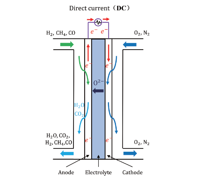
Solid oxide fuel cells (SOFCs) are power generation devices with high efficiency and low emissions. The high operating temperature (700~900 ℃) has impeded the wider adoption of SOFC stacks and limited their lifetime. This has motivated intense research efforts in developing SOFC stacks which can operate at lower temperatures. The thin electrolytes with a thickness smaller than 10 μm could shorten the ion conductive paths and reduce the associated ohmic loss, effectively improving the electrical performance of the low-temperature SOFC. The electrophoretic deposition process has the advantages of low cost and fast manufacturing speed. It is a potential candidate for large-scale commercial production of electrolyte thin films for low-temperature SOFC. In the present article, the research progress of electrophoretic deposition during the past ten years has been summarized. The key results and achievements for the important procedures of the electrophoretic deposition process, which are respectively substrate selection and pretreatment, stable suspension preparation, bubble elimination and heat treatment process, are also discussed and analyzed. The suggestions for future development of the electrophoretic deposition are also provided based on the requirements of large-scale commercialization of thin electrolyte for low-temperature SOFC.

Contents

1 Introduction

2 Fundamentals of the electrophoretic deposition process

3 Technical challenges and research progress of electrophoretic deposition process for the preparation of electrolyte thin films

3.1 Substrate selection and pretreatment

3.2 Stable suspension preparation

3.3 Bubble elimination

3.4 Heat treatment process

4 Conclusion and outlook

Cite this article

Bingguo Zhao , Yadi Liu , Haoran Hu , Yangjun Zhang , Zezhi Zeng . Electrophoretic Deposition in the Preparation of Electrolyte Thin Films for Solid Oxide Fuel Cells[J]. Progress in Chemistry, 2023 , 35(5) : 794 -806 . DOI: 10.7536/PC221104

1 Introduction

Solid Oxide Fuel Cell (SOFC) is an all-Solid-state energy conversion device that directly converts the chemical energy of Fuel into electrical energy at medium and high temperatures (500 ~ 900 ℃)[1,2]. Because of its high efficiency, wide power range and wide fuel adaptability, it has been paid close attention and studied by scholars at home and abroad in recent years[3][4][5]. The SOFC single cell is composed of a cathode, an electrolyte and an anode, and its working principle is shown in Fig. 1: At high temperature, O2 gets electrons at the three-phase reaction interface on the cathode side to generate O2- and passes through the dense electrolyte membrane, and reacts with H2, CO, etc. At the three-phase reaction interface on the anode side to generate electrons and electrochemical reaction products such as H2O and CO2, and the electrons pass through an external circuit to generate electric energy[6].
图1 SOFC 工作原理[5]

Fig. 1 Working principle of SOFC[5]

The electrolyte layer of conventional SOFC is thick and has low ionic conductivity, and SOFC requires high operating temperature (> 700 ℃) to reduce ohmic loss. The high operating temperature limits the choice of cathode, anode and linker materials, and leads to a long start-up time, which limits the application range of SOFC[7]. The low temperature of SOFC has become a research hotspot in recent years. Compared with the traditional high temperature SOFC, the medium and low temperature SOFC (400 ~ 800 ℃) has the advantages of short start-up time, good thermal shock resistance, slow component aging rate, high cell stability and low manufacturing cost, but the electrolyte ionic resistance and activation potential loss of SOFC increase significantly under the working condition of 400 ~ 650 ℃, which greatly reduces the electrochemical performance of SOFC[8][9][10]. The key to improve the power density of SOFC at medium and low temperatures is to study the high-performance electrolyte materials at medium and low temperatures to improve the ionic conductivity and the preparation process of ultra-thin electrolyte to shorten the ionic conduction path.
The research on electrolyte materials at intermediate and low temperatures focuses on oxygen ion-conducting electrolytes, mainly CeO2-based electrolytes, ZrO2-based electrolytes, lanthanum silicate electrolytes (La10Si6O27), LaGaO3 perovskite electrolytes and Bi2O3 based electrolytes. The ionic conductivity of electrolyte materials can be improved by doping metals or metal oxides[11][12][13][14][15]. Studies have shown that doping CaO, MgO and Y2O3 into ZrO2 can improve its ionic conductivity, and when the dopant concentration is close to the concentration required to completely stabilize the cubic fluorite structure, the ZrO2 electrolyte has the maximum ionic conductivity[16]. A recent study found that doping Cu in lanthanum silicate electrolyte can effectively promote the densification process of the electrolyte. In the temperature range of 550 ~ 800 ℃, the activation energy of the electrolyte phase decreases with the increase of Cu doping due to the larger conduction channel and mobility of Cu[17].
SOFC thin film preparation processes mainly include Tape casting, dip coating, spin coating, screen-printing, sol-gel, magnetron sputtering, plasma spraying, chemical vapor deposition, chemical solution deposition, physical vapor deposition (PVD), ultrasonic atomization pyrolysis, ultrasonic atomization spraying, Atomic layer deposition (ALD) and Electrophoretic deposition (ECD[18][19][20][21][22][23][24][25][26][27][28][29][30][31]. Fig. 2 compares the research heat changes of traditional thin film preparation processes such as tape casting and screen printing with new thin film preparation processes such as physical vapor deposition, atomic layer deposition and electrophoretic deposition (EPD) at home and abroad since the 21st century[32]. In the past two decades, the research results and enthusiasm of SOFC thin film preparation technology in domestic and foreign academia have been increasing day by day. At the same time, in the past decade, the research on new thin film preparation technologies such as PVD and ALD has gradually increased. Figure 2 shows that the number of papers published on EPD process is large and the number of papers published has been increasing in the past two decades, which fully demonstrates the recognition of the potential of EPD process by scholars at home and abroad.
图2 近20年SOFC薄膜制备工艺发展趋势(可通过Web of science 检索获取)[32]

Fig. 2 Development of SOFC thin film preparation process in recent 20 years (utilizing web of science to access the data)[32]

Among the SOFC thin film preparation technologies, the traditional thin film preparation technologies such as tape casting and screen printing can be used to prepare thick high-temperature SOFC electrolyte films (thickness > 10 μm), but it is difficult to process thin electrolyte films (thickness < 10 μm).Although the new thin film preparation processes such as ultrasonic atomization pyrolysis, physical vapor deposition and atomic layer deposition can process small area electrolyte membranes, they are limited by expensive processing equipment and long processing time, and are difficult to meet the needs of large-scale commercial production of SOFC ultra-thin electrolyte membranes[33]. EPD process has the advantages of simple equipment, low cost, high film density, easy thickness control, low requirement for substrate shape, high deposition rate (1 μm/min), suitable for multilayer system and good adhesion between layers, which has the potential to meet the needs of large-scale commercial preparation of ultra-thin electrolyte films for SOFC[31,34,35].
In this paper, the latest research progress of EPD process in the preparation of ultra-thin electrolyte for SOFC at home and abroad is introduced and discussed in detail. According to the requirements of large-scale commercial production, four main technical difficulties of EPD process are summarized: the selection and pretreatment of deposition substrate, the preparation of stable suspension, the elimination of bubbles during deposition and the subsequent heat treatment process. In this paper, the latest research progress and technological breakthroughs of domestic and foreign scholars in recent years for the above four technical bottlenecks are introduced in detail, and guidance and suggestions are given for the future EPD process in the large-scale commercial production process of SOFC ultra-thin electrolyte membrane.

2 Basic principle of electrophoretic deposition process

Electrophoretic deposition is a colloidal process, which uses particles in suspension to adsorb free charged ions to form charged colloidal particles. Under the action of external electric field, the colloidal particles in suspension move to the deposition substrate and finally deposit on the substrate with the substrate or deposition particles[34]. Electrophoretic deposition process is mainly divided into the following four stages: suspension preparation, substrate pretreatment, electrophoretic deposition process and subsequent heat treatment[36]. As shown in fig. 3, the electrophoretic deposition system is mainly composed of a power supply, a suspension, a substrate, and a counter electrode[37].
图3 电泳沉积系统示意图[37]

Fig. 3 Schematic of the electrophoretic deposition system[37]

Taking the preparation process of Gadolinium-doped ceria (GDC) thin film in SOFC as an example, the basic principle of electrophoretic deposition process is shown in Figure 4, which mainly includes the following four processes:[38]
图4 电泳沉积工艺基本原理示意图[38]

Fig. 4 Schematic of the working principle of electrophoretic deposition process[38]

(1) Particle transport process: When an electric field is applied on both sides of the cathode and anode, the particles in the suspension are driven by the voltage to move, in which the free hydrogen ions move to the cathode independently in the suspension, while the adsorbed hydrogen ions and GDC particles form charged particles, which move to the cathode side together under the drive of the electric field.
(2) Desorption process: When the charged particle reaches the suspension-sediment interface, the particle attaches to the existing sediment, and the adsorbed hydrogen ions on the particle detach from the particle surface.
(3) Charge diffusion process: The hydrogen ions released in the desorption process continue to move under the action of the electric field and diffuse through the deposit to the cathode side.
(4) Charge transfer process: hydrogen ions diffused to the surface of the cathode get electrons from the electrode and are reduced to generate hydrogen.

3 Main Technical Difficulties and Research Progress of Electrophoretic Deposition Process

Electrophoretic deposition (EPD) is an easy and low-cost thin film preparation process, but there are still a series of technical bottlenecks in this process, which makes it difficult to obtain stable and repeatable results under laboratory conditions[31]. The selection and pretreatment of deposition substrate, the preparation of stable suspension, the method of bubble elimination during deposition and the subsequent heat treatment are the key bottlenecks restricting the application of electrophoretic deposition process in the preparation of ultra-thin electrolyte membranes for SOFC.

3.1 Study on Selection and Pretreatment of Matrix

The influence of the conductivity of the substrate on the EPD process should be fully considered when selecting the substrate for the EPD process. For the deposition process of SOFC electrolyte film, the SOFC cathode with high conductivity at room temperature can be selected as the substrate.
Mahmoudimehr et al. Have shown that when the SOFC cathode is used as a supporting substrate, the electrochemical performance of the prepared SOFC is poor due to the large thickness of the SOFC cathode and the high polarization resistance[39]. In addition, during the high temperature sintering process, the non-conducting phase is easy to form between the electrode and the electrolyte. Taking the deposition of YSZ electrolyte film on strontium-doped lanthanum manganate (LSM) and yttria stabilized zirconia (YSZ) cathodes as an example, due to the stronger sintering ability of LSM, the porous structure of the cathode may be degraded by particle coarsening, the three-phase boundary of electrochemical reaction will be lost, and an insulating oxide layer will be generated between LSM and YSZ[40].
Due to the above factors, the SOFC anode is often used as the substrate in the EPD process, but the traditional metal composite materials used for the SOFC anode have poor conductivity under the EPD voltage condition, so the substrate needs to be specially treated first, mainly including porous treatment of the substrate, reducing atmosphere treatment and spraying conductive coating on the substrate[41][42][43].
The working principle of electrophoretic deposition on a non-conductive substrate is shown in Figure 5. Although the traditional metal composite material is difficult to conduct under EPD working conditions, the charge carriers in the suspension can pass through the pores of the composite material under the action of an external electric field.Causing particle movement and deposition on the surface of the substrate, but only when the substrate has interconnected pores can the establishment of conductive paths in the pores be guaranteed. Electrolyte particles not only deposit on the matrix, but also enter the pores to deposit and combine with the matrix, which eventually leads to the continuous closure of the pores, resulting in a rapid increase in the resistance in the electric field and a rapid decrease in the deposition rate[41]. In order to construct a better pore structure to increase the conductive path in the EPD process, a porous NiO-YSZ anode substrate was prepared by powder slip casting, and a YSZ film was deposited on the substrate by the EPD process. At a co-sintering temperature of 1250 ° C and an applied voltage of 30 V, dense YSZ films with a thickness of only 2.12 μm and 2.93 μm were obtained after deposition for 90 and 120 s, respectively[44].
图5 不导电基体上电泳沉积机制示意图[41]

Fig. 5 Schematic of mechanism of electrophoretic deposition on the non-conductive substrate[41]

Part of NiO can be reduced to metal Ni by treating the anode substrate in a reducing atmosphere, and the anode substrate which can conduct electricity under the condition of EPD voltage can be obtained. Gauckler et al. Successfully prepared an electrolyte film with a thickness of 15 μm by heat treating the non-conductive NiO-YSZ substrate in a reducing atmosphere (10%H2,90%Ar) at 700 ° C before using the EPD process to prepare the ultra-thin YSZ electrolyte, so that the metal oxide NiO in the substrate was reduced to the conductive metal Ni[42]. A recent study has shown that a conductive Ni-YSZ substrate can be obtained by reducing a NiO-YSZ anode substrate in a hydrogen controlled atmosphere at 850 ℃ for 5 H, and a YSZ electrolyte film with a thickness of 20 μm can be obtained by using the substrate in a constant voltage pulse EPD mode for 6 min[45].
In addition, the anode substrate can be coated with conductive materials such as graphite or carbon powder to make the substrate conductive under EPD voltage[46,47]. Talebi et al. Compared the effect of YSZ film deposited by EPD process on non-conductive NiO-YSZ composite and graphite-coated NiO-YSZ composite[48]. It was found that a uniform and dense electrolyte film could be obtained on both substrates, but when the electrophoretic deposition was carried out on the NiO-YSZ composite coated with graphite,The adhesion between the electrolyte film and the substrate is improved, and the quality of the deposited film is higher in the subsequent sintering process, while cracks are easy to form on the sintered YSZ film when a non-conductive substrate is used. Bozza et al. Deposited the electrolyte powder on the deposition substrate with carbon powder by EPD process. The carbon powder can not only be used as a pore-forming agent for the deposition substrate, but also make the deposition substrate conductive. Finally, a dense electrolyte membrane with a thickness of 30 μm was prepared[49]. Uchikoshi et al. Coated a nonconductive NiO-YSZ substrate with 0. 5 μm conductive polypyrrole to make the substrate conductive during EPD. After the GDC film was deposited, the polypyrrole was eliminated at a co-sintering temperature of 1400 ℃, and a dense GDC electrolyte film with a thickness of about 7. 5 μm was obtained[50].
Pikalova et al. Summarized the common requirements for the matrix in the EPD process through a large number of experimental studies.It mainly includes: high conductivity and uniform electric field on the surface, the thermal mechanical properties and sintering properties between the substrate and the deposited electrolyte film should be close, the porosity should be ≥ 35%, the pore size on the interface between the substrate and the electrolyte film should be ≤ 1 μm, the surface roughness of the deposited substrate should be ≤ 0.2 μm, and the stability of the substrate material during the sintering process of the electrolyte[51].

3.2 Study on Preparation of Stable Suspension

The preparation of stable suspensions is an important prerequisite for the fabrication of ultrathin electrolytes for SOFCs by electrophoretic deposition. In a stable suspension, the particles do not have the tendency to coagulate and the sedimentation rate is slow, which is essential for the deposition of a dense, adhesive and sintered electrolyte film on the substrate[52,53]. When the repulsion between adjacent charged particles in the suspension is greater than the attraction, the suspension is stable and the dispersion is good. As shown in Fig. 6, the electric potential on the slip plane (zeta potential, ζ) is a key parameter affecting many electrokinetic phenomena caused by space charge separation and interfacial electric double layer formation, and a higher Zeta potential indicates a higher repulsion between particles[54][54,55]. Bhattacharjee's study revealed the effect of Zeta potential on the stability of the suspension in the preparation of the suspension. In order to obtain a stable suspension, the Zeta potential value is generally not less than ± 20 mV[56]. Studies have shown that when the particle size distribution of the suspension is small, the mechanical stress in the deposit can be reduced and the uneven grain growth during sintering can be inhibited[57]. In the process of suspension preparation, the suspension with small particle size distribution can be obtained by ultrasonic, centrifugation and filtration[58][59][60]. In addition, in the synthesis process of electrolyte powder prepared by the traditional solid state reaction method or nitrate combustion method, the addition of charge agent and dispersant can reduce the agglomeration between electrolyte powder particles, thereby improving the stability of the suspension[31]. Nano-electrolyte powder with spherical particles, narrow particle size distribution and weak coagulation characteristics can be obtained by high-energy physical dispersion method, which can significantly improve the stability of suspension[61,62].
图6 粒子双电层区域及ζ(zeta)电位示意图[54]

Fig. 6 Schematic of particle electric double layer and ζ(zeta) potential[54]

Kalinina et al. Further showed that compared with the suspension obtained by the traditional preparation method, the suspension composed of nano-electrolyte powder formed an electric double layer with high ζ potential on the surface of the nanoparticles, which further improved the stability of the suspension[63].
The aggregation and sedimentation stability of the suspension can also be improved by selecting the appropriate dispersion medium. Because the process of water molecule electrolysis and gas evolution in the water medium in the EPD process will greatly affect the film density, the EPD dispersion medium used for the preparation of SOFC electrolyte film is generally organic medium, and water medium is rarely used[64]. The influence mechanism of the type of dispersion medium on the preparation of stable suspension with high ζ potential value has been compared, and the results show that the ζ potential value in the suspension decreases with the increase of the dielectric constant of the dispersion medium, and hydrogen ions tend to be adsorbed on the surface of oxide particles in the alcohol medium with relatively small dielectric constant[65]. Basu et al. further analyzed the effect of water content in the organic dispersion medium on the quality of EPD deposits. The study showed that when an alcohol solvent was used as the dispersion medium, the quality of EPD deposits was highly dependent on the water content, and a proper amount of water could not only promote the keto-enol reaction,It can also produce protons in the alcohol dispersion medium to increase the surface charge of the particles to improve the deposition rate. When the water content is 2% by volume, the maximum deposition mass of EPD can reach about 6 mg/cm3. However, too much water content will produce a large amount of electrolytic reaction gas and lead to serious defects on the surface of the film[66].
The pH value of the dispersion medium is also the key factor affecting the Zeta potential of the suspension[67]. The Zeta potential is positive at low pH and negative at high pH. In order to obtain a higher ζ potential and ensure the stability of the suspension, hydrochloric acid, alkali (triethanolamine (TEA), monoethanolamine (MEA), and 6-amino-1-heptanol (AH)), etc., are generally added to the dispersion medium[68][69]. Xiao et al. adjusted the pH value by adding TEA alkali to the suspension, and revealed that when the pH value of the dispersion medium increased from 7.4 to 8.4, the Zeta potential of the suspension increased, so that the deposit could be rearranged under the action of the electric field for further densification, and the bulk density of the coating prepared by EPD increased from 38% to 53%[69].
Dispersant is another means to improve the sedimentation stability of the suspension, which can make the oxide particles in the suspension have good dispersion and help to produce a uniform deposition layer. Common dispersants include phosphate ester (PE), polyethyleneimine (PEI), and iodine, which help to generate charges that adhere to the surface of the particles[70~72]. Basu et al. Prepared a stable suspension of YSZ nanoparticles in isopropanol medium using PE as a dispersant, and studied in detail the mechanism of the effect of PE concentration on the Zeta potential, pH value, conductivity and stability of the suspension[70]. When the concentration of PE is 0. 01 G/100 mL, the stability of YSZ nano-powder suspension is the best. Finally, a uniform electrolyte film with a high packing density and a thickness of only 3 μm was deposited on the NiO-YSZ porous substrate. Maghsoudipour et al. Studied the effect of adding iodine dispersant to suspensions with isopropanol and ethanol as dispersion media[45]. The results show that the increase of iodine concentration leads to the increase of conductivity and the decrease of pH value of suspension. It was found that the optimum concentration of iodine in ethanol-based suspension was 0. 5 G/L, and the maximum YSZ deposition quality could be obtained by EPD process. Mac Macías-Garc García et al. further studied the effect of iodine dispersant, and found that iodine can react with organic solvents (acetone, etc.) to form free protons, which are adsorbed on the surface of suspended 3YS Z particles, thus increasing their surface positive charge[73]. When the iodine concentration is 0. 2 G/L and the EPD current intensity is 5 mA, the best deposition effect can be obtained for 0. 1 G/L suspension.

3.3 Study on Bubble Elimination Method

During the electrophoretic deposition process, the bubbles generated on the substrate will seriously affect the uniformity, density and green density of the deposited film. Compared with the aqueous dispersion medium, the use of organic dispersion medium can reduce the amount of bubbles, but can not completely eliminate bubbles, and because of the limited surface charge of charged particles in the organic dispersion medium and the high resistance of the dispersion medium itself, it generally requires hundreds of volts of high voltage drive[74~76]. Therefore, it is very important to study the bubble elimination method in EPD process. Film deposition and bubble generation generally occur on the same electrode. By separating the deposition process from the bubble generation process of electrochemical reaction, the damage of bubbles to the deposited film can be effectively avoided.
The influence of bubbles can be well eliminated by separating the deposition process and the bubble generation process by electrolysis and using a new substrate with the ability to absorb hydrogen. Tabellion et al. Separated the deposition process from the electrochemical reaction process by placing an ion permeable membrane between the two electrodes, and obtained a bubble-free dense deposit film on the dialysis membrane, while the charged ions passed through the dialysis membrane and reached the electrode to complete the electrochemical reaction[77]. In addition, if the generated gas is absorbed on the electrode, the damage of the film by the bubbles can also be avoided. Studies have compared the characteristics of films deposited on nickel, platinum, stainless steel and palladium substrates, and found that the uniform deposited films obtained on palladium substrates with excellent hydrogen absorption capacity have no obvious defects[78]. Sakurada et al. Studied the deposition of 3YSZ thin films on stainless steel substrates by EPD process, and used hydroquinone-doped aqueous dispersion medium to form a suspension[79]. The study shows that in alkaline solution environment, the hydrogen produced in the EPD process can be consumed by the chemical reaction of hydroquinone in the dispersion medium, and when the concentration of hydroquinone is 0.05~0.15 mol/m3, a dense film can be obtained.
Bubble formation in EPD process can be suppressed to some extent by separating particle deposition from ion electrochemical reaction, but this method significantly increases the cost of EPD process and limits its prospect of large-scale commercial application. In recent years, the research focus on bubble elimination has gradually turned to the simple electric field control method to suppress the generation of bubbles. There are two main methods of EPD voltage regulation: pulse DC EPD (DC-EPD) and AC EPD (AC-EPD).
Uchikoshi et al. Proposed a square-wave pulse voltage EPD mode to obtain dense, bubble-free alumina deposits in aqueous suspensions[80]. By comparing the deposition effect under two EPD voltage modes of continuous DC and pulsed DC, they found that pulsed DC EPD could reduce the amount of deposition and the number of bubbles simultaneously. Fig. 7 shows that a uniform and dense deposited film can be obtained under the operating conditions of an applied voltage of 20 V and a pulse width of 0.015 to 0.02 s. Cathodic deposition and anodic deposition pulse EPD were further compared, and it was found that cathodic deposition pulse EPD was more convenient and easy to control than anodic deposition pulsed EPD. Maghsoudipour et al. Studied the effects of pulse width, applied voltage and total deposition time on the quality of deposited films in constant voltage pulse EPD, and revealed that the deposition yield increased with the increase of pulse width, applied voltage and total deposition time.A dense YSZ electrolyte membrane with a thickness of about 17 μm was successfully prepared on the porous Ni-YSZ cermet in the EPD mode with a voltage of 35 V, a pulse width of 1 ms, and a duty cycle of 50%[45,81].
图7 不同脉冲宽度下电解质薄膜质量对比(镍基体,20 V外加电压)[80]

Fig. 7 Quality comparison of electrolyte films under different pulse widths (Ni substrate, 20 V applied voltage)[80]

The influence of bubbles can also be effectively eliminated by using an alternating current electric field,The following processes may occur: the reverse current drives a half-reaction on the electrode to convert the gas products formed into soluble reactants, the spent reactant layer is restored, and the weakly adsorbed particles with the remaining surface charge are removed from the deposit surface to obtain a denser green body[47,82]. The current charges the double-layer capacitance at the electrode/electrolyte interface in both pulsed DC and asymmetric AC fields. As the current frequency increases, more current flows through the double layer capacitance, and the bubbles associated with the Faraday half-reaction decrease. It is pointed out that there is a threshold value for the current frequency. When the frequency is higher than the threshold value, almost all the current flows through the double-layer capacitance, and the bubble evolution can be ignored[83,84]. Liu et al. Studied the AC-EPD process on aqueous suspension of gadolinium doped cerium on titanium plate[83]. When the pH value of the suspension is 9. 0, as the frequency increases from 10 Hz to 1 kHz, the bubble evolution process gradually weakens, the effect on the quality of the deposited film gradually decreases, and the deposition yield increases linearly with time. When the AC frequency is increased to 1 kHz, a smooth electrolyte film without visible defects can be obtained. Liu et al. Also studied the effects of parameters such as the width percentage and voltage ratio of the AC field on the AC-EPD. The results show that the optimum forward width percentage and voltage ratio of AC-EPD are 50% and 10/4, respectively. In a recent study, in order to increase the green density of the GDC layer and reduce the sintering temperature for GDC densification, AC-EPD was used to eliminate the bubble evolution, and the bubble generation was avoided by maintaining a high frequency alternating current during the EPD process so that the total current was controlled by the charging current. It is found that the maximum deposition rate of about 8.5 mg/cm2 can be obtained at the optimal deposition frequency of 500 Hz, and the deposition rate increases with the increase of voltage ratio and the percentage of forward width. A dense electrolyte film with a thickness of only 6 μm was obtained by sintering the deposited GDC film at 1250 ℃[38].

3.4 Study on Heat Treatment Process

The sintering temperature and sintering atmosphere in the heat treatment process are the key factors affecting the quality of the film. The sintering temperature directly affects the grain size, surface roughness, and ionic conductivity of the electrolyte film. Talebi et al. Studied the influence mechanism of sintering temperature on the microstructure, surface roughness and conductivity of YSZ thin films prepared by EPD process, and obtained dense films without obvious pore cracks when the temperature was higher than 1400 ℃[85]. The results show that increasing the sintering temperature can promote the growth of small YSZ grains and improve the density and smoothness of the deposited YSZ films. In addition, they pointed out that the YSZ film sintered at 1400 ℃ had the best conductivity. In a later study, the lanthanum strontium cobalt iron-samarium doped cerium carbonate (LSCF-SDCC) composite cathode was prepared on the samarium doped cerium carbonate (SDCC) substrate by EPD, and the effect of sintering temperature of the LSCF-SDCC composite cathode film on its polarization resistance was studied by energy dispersive spectroscopy (EDS). The results show that the polarization resistance per unit area of the LSCFSDCC sintered at 600 ℃ is only 0.027Ω/cm2 at 650 ℃[86].
The sintering temperature also has an important effect on the bonding properties between the porous matrix and the electrolyte film. Chuankrerkkul et al. Deposited YSZ thin films on porous NiO-YSZ anode substrates prepared by powder slip casting by EPD process, and studied the effect of different co-sintering temperatures on the microstructure of YSZ thin films[44]. The results show that with the increase of sintering temperature, the grain size increases and the porosity decreases. They found that the anode prepared at 1350 ° C was significantly bent and had insufficient pores, but there were obvious pores on the YSZ electrolyte prepared at 1200 ° C. Kalinina et al. Deposited BaCe0.5Zr0.3Y0.1Yb0.1O3-δ/Ce0.8Sm0.2 O 1 . 9 (BCZYYbO-CuO/SDC) bilayer electrolyte on non-conductive porous NiO-SDC anode substrate by EPD process[87]. As shown in fig. 8, after sintering at 1400 ℃ for 5 H, the electrolyte layer had multiple fractures and the matrix had obvious bending. The reduction of the anode matrix and the subsequent oxidative sintering cause large mechanical stresses in the matrix-electrolyte structure and eventually destroy the cell structure.
图8 沉积的BCZYYbO-CuO/SDC双层电解质光学照片:(a)沉积干燥后;(b)1400 ℃空气中烧结5 h[87]

Fig. 8 Optical photographs of the deposited BCZYYbO -CuO/SDC bilayer electrolyte: (a) after deposition and drying; (b) sintered in air at 1400 ℃ for 5 h[87]

The sintering temperature also has an important effect on the co-sintering characteristics between the matrix and the electrolyte. Generally, the co-sintering temperature of the electrolyte film and the porous anode substrate obtained by EPD is about 1300 ℃. Excessive sintering temperature will destroy the mechanical structure of the substrate and lead to the coarsening of the particles in the porous substrate, resulting in the reduction of the three-phase reaction interface and ultimately affecting the electrochemical performance of SOFC[88]. On the premise of ensuring the performance of the electrolyte film, it is of great significance to study the methods of reducing the co-sintering temperature between the anode substrate and the electrolyte film for the low temperature SOFC. The co-sintering temperature in the heat treatment process can be effectively reduced and the density of the film can be ensured by adding a sintering aid into the suspension, using nanoparticles and a reaction bonding process[89][90][91]. Xiao et al. Showed that :Fe2O3 is an effective sintering aid for densification of tetravalent oxides (ZrO2 as well as CeO2), and they found that the position occupied by Fe3+ in the YSZ lattice depends on the YSZ phase and the oxygen vacancy concentration at room temperature, and the study revealed that Fe3+ is a key factor for densification and grain growth of YSZ during sintering[92]. In a follow-up study, Xiao et al. Added Fe2O3 as a sintering aid to the suspension to reduce the co-sintering temperature of the matrix and YSZ electrolyte, and successfully reduced the co-sintering temperature to 1150 ° C[93]. Liu et al. Used EPD to deposit GDC barrier layer on YSZ electrolyte film by adding FeO1.5 as sintering aid in the GDC suspension to reduce the sintering temperature and improve the sintering ability of the deposited film[94]. It is found that FeO1.5 can increase the concentration of oxygen vacancies to obtain higher GDC ionic conductivity, and remove the SiO2 impurities at the interface to enhance the charge transfer process. The study reveals that a small amount of FeO1.5 can increase the contact area between the deposited particles to improve the densification rate, and finally successfully reduce the sintering temperature by 200 ℃. In the deposited green body, the distribution of sintering AIDS is generally uneven, which will lead to the deterioration of the quality of the deposited green body and the uneven structure of the electrolyte film after sintering. This may be due to the difference in ζ potential between the deposit particles and the sintering aid particles, which makes it impossible to prepare a stable suspension with good dispersion and ultimately affects the quality of the deposited film[95]. Therefore, it is necessary to carefully select the sintering AIDS suitable for EPD.
The preparation of nanoparticle suspension and the use of reactive bonding process can also reduce the co-sintering temperature. Yamamoto et al. Prepared a suspension by grinding GDC nanocubic crystals synthesized by organic ligand-assisted hydrothermal method, distilled water and ammonium polyacrylate, and deposited GDC films on LSCF substrate by EPD with CuO as sintering agent[88]. The results reveal that the fine nanoparticles have high surface free energy, which can promote the diffusion of atoms during the sintering process, and finally the GDC electrolyte film with a thickness of only 1 μm can be obtained by co-sintering at a low temperature of 1000 ℃. Fig. 9 is a scanning electron microscope image of the cross section of the GDC electrolyte and the GDC/LSCF support. It can be seen that the electrolyte film and the substrate are well bonded without obvious warping or falling off. Aghajani et al. Used the reactive bonding process to reduce the co-sintering temperature by adding Ni particles to YSZ[96]. The bonding process in the co-sintering process was revealed: at the co-sintering temperature, the oxidation of Ni particles caused volume expansion, which could compensate for the volume shrinkage in the sintering of the coating, and finally reduced the co-sintering temperature by about 300 ℃.
图9 1000 ℃烧结下(a)GDC 薄膜表面和(b)GDC/LSCF支撑体横截面的扫描电镜图片;(c)和(d)分别为(a)和(b)图的高倍率放大图[88]

Fig. 9 Surface and cross-sectional SEM images of (a) GDC film and (b) GDC film/LSCF support sintered at 1000 ℃. High-magnification of the (c) surface and (d) cross-sectional SEM images of (a) and (b), respectively[88]

In the traditional heat treatment process, the anode substrate is usually pre-sintered at a moderate temperature before the deposition of the electrolyte. Savo et al. Directly co-sintered the unpresintered anode and the YSZ electrolyte film prepared by EPD at 1350 ℃, and then cooled to 650 ℃ to ensure the complete oxidation and decomposition of volatile compounds in the anode[97]. The dense and crack-free YSZ film with a thickness of 6 ~ 8 μm was obtained while the porosity of the substrate was ensured, and the adhesion between the electrolyte film and the anode substrate was good.
Sintering atmosphere is also an important factor affecting the quality of electrolyte films. Chen et al. Studied the preparation of YSZ thin films containing aluminum and nickel by EPD process in methane gas environment[98]. It was found that the volume of the composite film was easy to shrink during high temperature sintering, resulting in the formation of pores and microcracks in the film, and zirconium carbide (ZrC) was easy to form near the YSZ crystal-pore-crack interface in methane atmosphere.It can improve the density of the film, fill the defects such as holes and cracks in the film, and further improve the density and high temperature oxidation resistance of the coating. Sintering atmosphere plays an important role in improving the quality of EPD films, but there are few studies in this direction, which needs further study.
Table 1 is a summary of the heat treatment process for the preparation of SOFC ultrathin electrolyte films by electrophoretic deposition.
表1 电泳沉积法制备SOFC超薄电解质薄膜工艺热处理过程

Table 1 Heat treatment process of SOFC electrolyte thin films prepared by electrophoretic deposition

Electrolyte/
thickness/size
Substrate/dispersant/dispersion medium Heat treatment(temperature, atmosphere) EPD mode/
deposition time
Distance between substrate and electrode Electrochemical performance ref
YSZ/2.95 μm/- Substrate: porous NiO-YSZ anode prepared by PIM method
Dispersant: 5 wt%
polyethylene glycol
Dispersion medium: ethanol
Sintering: co-sintered at 1200~1400 ℃ for 1h (heating rate 3 ℃/min); Air atmosphere
Reduction: reduced at 1250~1350 ℃ until open circuit voltage and impedance did not change; humidified H2 atmosphere
Voltage: 20~30 V
Deposition time: 30~180 s
Peak power density: 0.013 W/cm2
(800 ℃)
44
GDC/~
7.5 μm/-
Substrate: porous NiO-YSZ anode
Dispersant: polyethyleneimine
Dispersion medium: ethanol
Sintering: co-sintered at
1400 ℃ for 2 h
Voltage: 50 V(DC) 2 cm Peak power density: 0.011 W/cm2
(800 ℃)
50
SDC/10 μm/~1.2 cm2 Substrate: porous NiO-BCS-CuO
Dispersant: none
Dispersion medium: isopropanol and acetylacetone
Drying: dried at room temperature for 24 h after EPD
Sintering: co-sintered at
1450 ℃ for 5 h
Voltage: 200 V
Deposition time: 60 s
10 mm Power density:
0.072 W/cm2
(750 ℃, 0.5 V)
67
YSZ/~
3 μm/25×
25 mm2
Substrate: porous NiO-YSZ anode with a conductive steel plane at the back
Dispersant: Phosphate ester (PE)
Dispersion medium: isopropanol
Sintering: sintered at 1000~1200 ℃ for 2 h Voltage: 10~70 V
Deposition time:
1~6 min
4 cm Peak power density: 0.90 W/cm2
(800 ℃)
70
YSZ/7.98 μm/- Substrate: Stainless steel AISI-310
Dispersant: iodine
Dispersion medium: isopropanol or acetone
Preheating: substrate is
preheated at 300 ℃ for
60 min; air atmosphere
Current: 3~10 mA
Deposition time: 5~25 min
1 cm 73
GDC/1 ~
2 μm /25 ×
25 mm2
Substrate: LSCF cathode
Dispersant: 1.25% polyacrylic acid ammonium (PAAA)
Dispersion medium: water
Drying: dried at 60 ℃ for 1 h
Sintering: co-sintered at
1000 ℃ for 2 h (heating rate
2 ℃/min)
Voltage: 100 V
(DC)
Deposition time:
2 min
15 mm 88
GDC/6 μm /4 cm2 Substrate: YSZ electrolyte
Dispersant: iodine
Dispersion medium: ethanol
Sintering: YSZ and NiO-YSZ are co-sintered at 1400 ℃ for 4 h
Sintering: GDC and LSCF-GDC are co-sintered at
1150 ℃ for 1.5 h
Voltage: -100 V ~
+80 V (AC)
1 cm Peak power density: 0.99 W/cm2
(800 ℃)
94
38
YSZ/
2.92 μm /-
Substrate: Ni-YSZ anode
Dispersant: none
Dispersion medium: acetylacetone
Drying: dried at room temperature for a night after EPD
Sintering: co-sintered at
1400 ℃ for 2 h
Voltage: 25 V
Deposition time:
3 min
1 cm Peak power density: 0.477 W/cm2
(800 ℃, H2)
99
YSZ/10 μm/- Substrate: porous NiO-YSZ anode
Dispersant: Darvan 821-A
Dispersion medium: acetylacetone
Drying: dried at room temperature for a night after EPD
Sintering: co-sintered at
1450 ℃ for 5 h
Voltage: 50~300 V (DC)
Deposition time: 1~5 min
10 mm Peak power density: 0.624 W/cm2
(800 ℃)
100
YSZ/5 μm/- Substrate: porous NiO-YSZ anode
Dispersant: 0.1 g/L iodine, 5 vol% acetylacetone and 2 vol% water
Dispersion medium: isopropanol
Sintering: co-sintered at
1400 ℃ for 6 h (heating to 800 ℃ with heating rate of
50 ℃/h and then keeping
30 min; then heating to
1400 ℃ with heating rate of
75 ℃/h and keeping 6 h)
Voltage: 15~40 V (DC)
Deposition time: 1~4 min
2 cm Power density: 0.91 W/cm2 (800 ℃, 0.7 V) 101
YSZ/
~2.5 μm/-
Sintering: co-sintered at
1400 ℃ for 2 h (heating rate 1 ℃/min)
Voltage: 30 V
Deposition time:
2 min
Peak power density: 0.077 W/cm2
(800 ℃)
102
BCSCuO/
8 μm/
~1.2 cm2
Substrate: SDC
Dispersant: iodine
Dispersion medium: isopropanol and acetylacetone
Sintering: co-sintered at
1450 ℃ for 5 h
Voltage: 20~80 V
Deposition time: 1~ 3 min
1 cm 103
BSCF/
10 μm/-
Substrate: porous BSCF
Dispersant: polymethylmethacrylate
Dispersion medium: reagent-grade ethanol
Sintering: co-sintered at
1100 ℃ for 3 h
Voltage: 150 V
Deposition time:
5 min
10 mm 104

4 Conclusion and prospect

SOFC is an efficient and clean energy conversion device, in which low temperature has become a current research hotspot, but the ion internal resistance of SOFC is too large when it works at medium and low temperature, resulting in a significant reduction in output power. Fabricating ultrathin electrolyte to shorten the ion conduction path is the key way to improve the power density of SOFC at medium and low temperatures. Among the existing SOFC electrolyte thin film preparation processes, the electrophoretic deposition process has great potential for large-scale commercial production due to its advantages of simple equipment, high film preparation density, and easy thickness control.
The selection and pretreatment of matrix, the preparation of stable suspension, the elimination of bubbles and the heat treatment are the key bottlenecks restricting the development of EPD process. In the current study, the anode was mainly used as the deposition substrate due to the reaction between the cathode and the electrolyte. Increasing the porosity of the substrate and coating conductive materials on the substrate to construct the conductive path in the anode substrate during EPD process are the current research hotspots.
The preparation of stable suspension has a crucial effect on the density and adhesion of electrolyte films. Selecting appropriate dispersant and dispersion medium can effectively adjust the pH value of the suspension, increase the ζ potential on the surface of the deposited particles, and improve the stability of the suspension.
In the process of electrophoretic deposition, there is usually a water electrolysis reaction, and the gas produced by the reaction will cause bubble defects in the film. Bubbles can be effectively eliminated by separating the deposition from the electrolysis process or by using a gas-absorbing matrix material, but these methods are often too costly. Bubbles can be effectively eliminated and the density of the deposited film can be improved by means of pulsed DC and AC electric field control in the electrophoretic deposition process.
The heat treatment process has an important effect on the quality of the electrolyte film. Increasing the sintering temperature can improve the grain size of the electrolyte, increase the density of the electrolyte film and improve the adhesion between the electrolyte film and the matrix, but too high temperature will lead to the damage of the matrix and the coarsening of the particles in the matrix. The sintering temperature can be effectively reduced by adding sintering AIDS, preparing nanoparticle suspension and reactive bonding process. In addition, the defects of the electrolyte membrane can be repaired and the density of the electrolyte membrane can be improved to a certain extent by controlling the sintering atmosphere.
Although EPD has made good progress in the preparation of SOFC electrolyte films, there are still some problems to be solved according to the actual needs of large-scale commercial production and application:
(1) Increase the area of the prepared film and further reduce the thickness of the film. At present, the area of the prepared electrolyte film is small (usually <10 cm2) and the thickness is thick (usually > 2 μm), so the preparation process of the suspension should be further optimized to improve the ζ potential value of the suspension by selecting appropriate dispersant and dispersion medium, and to improve the deposition performance by preparing smaller suspension particles (such as nanoparticles), so as to obtain thinner and larger electrolyte films.
And (2) the density of the membrane is further improved and the process cost is reduced. Due to the limitation of the particle size and the bubble evolution process on the substrate, the green density and the film density are difficult to be guaranteed. It is necessary to further improve the suspension configuration and bubble elimination methods, especially the low-cost and easy-to-control pulsed DC and AC electric field control methods, and to explore the influence and optimal setting of electric field parameters such as pulse frequency, duty cycle and voltage. In addition, the new suspension can improve the membrane quality, but it also greatly increases the cost of EPD, requiring a cheaper and high-quality suspension configuration.
And (3) reducing the co-sintering temperature between the deposition substrate and the electrolyte film. The deposited electrolyte film needs to be sintered at 1300 ℃ ~ 1400 ℃ to improve its grain size and ionic conductivity, but too high sintering temperature may lead to the failure of the metal support of the medium and low temperature metal supported SOFC, which restricts the large-scale commercialization of the medium and low temperature SOFC stack. At present, there are few studies on the preparation of nanoparticle suspension and the use of reactive bonding process to reduce the co-sintering temperature, which need further study. Reducing the co-sintering temperature by adding sintering AIDS to the suspension is a hot topic of current research, and the matching of ζ potential values between the deposited particles of the suspension and the sintering AIDS particles can be further considered in the future, so as to avoid the decrease of ζ potential values of the suspension caused by the sintering AIDS particles and affect the stability of the suspension.
[1]
Zhang Y, Knibbe R, Sunarso J, Zhong Y J, Zhou W, Shao Z P, Zhu Z H. Adv. Mater., 2017, 29(48): 1700132.

[2]
Zeng Z Z, Hao C K, Zhao B G, Qian Y P, Zhuge W L, Wang Y Q, Shi Y X, Zhang Y J. Int. J. Green Energy, 2022, 19(10): 1132.

[3]
Zhao B G, Zeng Z Z, Hao C K, Qian Y P, Zhuge W L, Zhang Y J. J. Eng. Thermophys., 2022, 43(11): 3029.

(赵秉国, 曾泽智, 郝长坤, 钱煜平, 诸葛伟林, 张扬军. 工程热物理学报, 2022, 43(11): 3029.).

[4]
Essaghouri A, Zeng Z Z, Zhao B G, Hao C K, Qian Y P, Zhuge W L, Zhang Y J. Energies, 2022, 15(19): 7048.

[5]
Zhao B G, Zeng Z Z, Hao C K, Essaghouri A, Qian Y P, Zhuge W L, Wang Y Q, Shi Y X, Zhang Y J. Int. J. Energy Res., 2022, 46(13): 18426.

[6]
Zeng Z Z, Qian Y P, Zhang Y J, Hao C K, Dan D, Zhuge W L. Appl. Energy, 2020, 280: 115899.

[7]
Hao C K, Zeng Z Z, Zhao B G, Qian Y P, Zhuge W L, Wang Y Q, Shi Y X, Zhang Y J. Appl. Therm. Eng., 2022, 211: 118453.

[8]
Zeng Z Z, Zhao B G, Hao C K, Essaghouri A, Qian Y P, Zhuge W L, Wang Y Q, Shi Y X, Zhang Y J. Appl. Therm. Eng., 2023, 219: 119577.

[9]
Zuo N, Zhang M L, Mao Z Q, Gao Z, Xie F C. J. Eur. Ceram. Soc., 2011, 31(16): 3103.

[10]
Kim Y B, Park J S, Gür T M, Prinz F B. J. Power Sources, 2011, 196(24): 10550.

[11]
Jaiswal N, Tanwar K, Suman R, Kumar D, Upadhyay S, Parkash O. J. Alloys Compd., 2019, 781: 984.

[12]
Ryu S, Yu W, Chang I, Park T, Cho G Y, Cha S W. Ceram. Int., 2020, 46(8): 12648.

[13]
Fallah Vostakola M, Amini Horri B. Energies, 2021, 14(5): 1280.

[14]
Wang L S, Li C X, Li C J, Yang G J. Electrochimica Acta, 2018, 275: 208.

[15]
Chen R, Zhang S L, Li C J, Li C X. J. Therm. Spray Technol., 2021, 30(1/2): 196.

[16]
Yang B C, Go D, Oh S, Woo Shin J, Kim H J, An J. Appl. Surf. Sci., 2019, 473: 102.

[17]
Yang T R, Zhao H L, Fang M Y, Świerczek K, Wang J, Du Z H. J. Eur. Ceram. Soc., 2019, 39(2/3): 424.

[18]
Baquero T, Escobar J, Frade J, Hotza D. Ceram. Int., 2013, 39(7): 8279.

[19]
Suzuki T, Hasan Z, Funahashi Y, Yamaguchi T, Fujishiro Y, Awano M. Electrochem. Solid-State Lett., 2008, 11(6): B87.

[20]
Li J Y, Fan L J, Hou N J, Zhao Y C, Li Y D. RSC Adv., 2022, 12(21): 13220.

[21]
Somalu M R, Muchtar A, Daud W R W, Brandon N P. Renew. Sustain. Energy Rev., 2017, 75: 426.

[22]
Dayaghi A M, Askari M, Rashtchi H, Gannon P. Surf. Coat. Technol., 2013, 223: 110.

[23]
Guo Y B, Zhao Z, Li Y C, Qi H Y, Cheng M J. Chinese Journal of Power Sources, 2020, 44(09): 1297.

(郭意博, 赵哲, 李宇超, 戚惠颖, 程谟杰. 电源技术, 2020, 44(09): 1297.).

[24]
Du K, Song C, Yu M, Chen D, Guo Y, Liu T K, Yang C H, Liu M. Journal of the Chinese Ceramic Society, 2022, 50(07): 1929.

(杜柯, 宋琛, 余敏, 陈丹, 郭宇, 刘太楷, 杨成浩, 刘敏. 硅酸盐学报, 2022, 50(07): 1929.).

[25]
Sakai T, Kato T, Katsui H, Tanaka Y, Goto T. Mater. Today Commun., 2020, 24: 101184.

[26]
Lee H, Park J, Lim Y, Yang H, Kim Y B. J. Alloys Compd., 2021, 861: 158397.

[27]
Han F, Riegraf M, Sata N, Bombarda I, Liensdorf T, Sitzmann C, Langhof N, Schafföner S, Walter C, Geipel C, Costa R. ECS Trans., 2021, 103(1): 139.

[28]
García Sánchez M F, Ponce Rosas I, MalagÓn García J F, Alberto Andraca Adame J, Lartundo-Rojas L, Santana G. Phys. Status Solidi A, 2020, 217(22): 2000235.

[29]
Liu M F, Uba F, Liu Y. J. Am. Ceram. Soc., 2020, 103(9): 5325.

[30]
Yang H, Lee H, Lim Y, Kim Y B. J. Am. Ceram. Soc., 2021, 104(1): 86.

[31]
Pikalova E Y, Kalinina E G. Renew. Sustain. Energy Rev., 2019, 116: 109440.

[32]
https://www.webofscience.com/wos/alldb/basic-search.

[33]
Besra L, Compson C, Liu M L. J. Power Sources, 2007, 173(1): 130.

[34]
Sharkawi N A, Azmi M A, Jaidi Z, Abd. Rahman H, Ahmad S, Mahzan S, Ismail A, Tajul Arifin A M, Zakaria H, Hassan S. Journal of Advanced Mechanical Engineering Applications, 2021, 2(2): 9.

[35]
Chasta G, Himanshu, Dhaka M S. Int. J. Energy Res., 2022, 46(11): 14627.

[36]
Yu J, Zhang Y, Pu J, Shen S X, Wang L J, Zhou F. Hot Working Technology, 2018, 47(08): 11.

(于静, 张勇, 蒲健, 沈淑馨, 王利捷, 周凡. 热加工工艺, 2018, 47(08): 11.).

[37]
Lowrance Y N, Azmi M A, Rahman H A, Rahman N F A, Zakaria H, Hassan S. Key Eng. Mater., 2022, 908: 555.

[38]
Hu S S, Finklea H, Li W Y, Li W, Qi H, Zhang N, Liu X B. ACS Appl. Mater. Interfaces, 2020, 12(9): 11126.

[39]
Chelmehsara M E, Mahmoudimehr J. Int. J. Hydrog. Energy, 2018, 43(32): 15521.

[40]
Mahato N, Banerjee A, Gupta A, Omar S, Balani K. Prog. Mater. Sci., 2015, 72: 141.

[41]
Besra L, Compson C, Liu M L. J. Am. Ceram. Soc., 2006, 89(10): 3003.

[42]
Will J, Hruschka M K M, Gubler L, Gauckler L J. J. Am. Ceram. Soc., 2001, 84(2): 328.

[43]
van Tassel J, Randall C A. J. Mater. Sci., 2004, 39(3): 867.

[44]
Chauoon S, Meepho M, Chuankrerkkul N, Chaianansutcharit S, Pornprasertsuk R. Thin Solid Films, 2018, 660: 741.

[45]
Oskouyi O E, Maghsoudipour A, Shahmiri M, Hasheminiasari M. J. Alloys Compd., 2019, 795: 361.

[46]
Azarian Borojeni I, Raissi B, Maghsoudipour A, Kazemzad M, Talebi T. Key Eng. Mater., 2015, 654: 83.

[47]
Hu S S, Li W Y, Finklea H, Liu X B. Adv. Colloid Interface Sci., 2020, 276: 102102.

[48]
Talebi T, Raissi B, Haji M, Maghsoudipour A. Int. J. Hydrog. Energy, 2010, 35(17): 9405.

[49]
Bozza F, Polini R, Traversa E. Electrochem. Commun., 2009, 11(8): 1680.

[50]
Suzuki H T, Uchikoshi T, Kobayashi K, Suzuki T S, Sugiyama T, Furuya K, Matsuda M, Sakka Y, Munakata F. J. Ceram. Soc. Japan, 2009, 117(1371): 1246.

[51]
Pikalova E Y, Kalinina E G. Int. J. EQ, 2019, 4(1): 1.

[52]
Besra L, Liu M. Prog. Mater. Sci., 2007, 52(1): 1.

[53]
Khanali O, Rajabi M, Baghshahi S. Journal of Ceramic Processing Research, 2017, 18(10): 735.

[54]
Aznam I, Mah J C W, Muchtar A, Somalu M R, Ghazali M J. J. Zhejiang Univ. Sci. A, 2018, 19(11): 811.

[55]
Barbati A C, Kirby B J. ELECTROPHORESIS, 2016, 37(14): 1979.

[56]
Bhattacharjee S. J. Control. Release, 2016, 235: 337.

[57]
Visco S J, Jacobson C, DeJonghe L C. U.S. Patent No. 6, 887, 361. 3 May 2005.

[58]
Dukhin A S, Goetz P J, Wines T H, Somasundaran P. Colloids Surf. A Physicochem. Eng. Aspects, 2000, 173(1/3): 127.

[59]
Kalinina E G, Efimov A A, Safronov A P. Thin Solid Films, 2016, 612: 66.

[60]
Yadav T. U.S. Patent No.7, 683, 098. 23 Mar. 2010.

[61]
Pikalova E Y, Nikonov A V, Zhuravlev V D, Bamburov V G, Samatov O M, Lipilin A S, Khrustov V R, Nikolaenko I V, Plaksin S V, Molchanova N G. Inorg. Mater., 2011, 47(4): 396.

[62]
Osipov V V, Kotov Y A, Ivanov M G, Samatov O M, Lisenkov V V, Platonov V V, Murzakaev A M, Medvedev A I, Azarkevich E I. Laser Phys., 2006, 16(1): 116.

[63]
Kalinina E G, Samatov O M, Safronov A P. Inorg. Mater., 2016, 52(8): 858.

[64]
Ammam M. RSC Adv., 2012, 2(20): 7633.

[65]
Negishi H, Yamaji K, Sakai N, Horita T, Yanagishita H, Yokokawa H. J. Mater. Sci., 2004, 39(3): 833.

[66]
Das D, Basu R N. Mater. Res. Bull., 2013, 48(9): 3254.

[67]
Pikalova E, Osinkin D, Kalinina E. Membranes, 2022, 12(7): 682.

[68]
Guo F W, Javed A, Shapiro I P, Xiao P. J. Eur. Ceram. Soc., 2012, 32(1): 211.

[69]
Xu H, Shapiro I P, Xiao P. J. Eur. Ceram. Soc., 2010, 30(5): 1105.

[70]
Das D, Bagchi B, Basu R N. J. Alloys Compd., 2017, 693: 1220.

[71]
Matsuda M, Hashimoto M, Matsunaga C, Suzuki T S, Sakka Y, Uchikoshi T. J. Eur. Ceram. Soc., 2016, 36(16): 4077.

[72]
Kalinina E G, Pikalova E Y. Russ. J. Phys. Chem., 2021, 95(9): 1942.

[73]
Pantoja-Pertegal J L, Díaz-Parralejo A, Macías-García A, Sánchez-González J, Cuerda-Correa E M. Ceram. Int., 2021, 47(10): 13312.

[74]
Schwer C, Kenndler E. Anal. Chem., 1991, 63(17): 1801.

[75]
Ishihara T, Sato K, Takita Y. J. Am. Ceram. Soc., 1996, 79(4): 913.

[76]
Zhang H, Zhan Z L, Liu X B. J. Power Sources, 2011, 196(19): 8041.

[77]
Tabellion J, Clasen R. J. Mater. Sci., 2004, 39(3): 803.

[78]
Uchikoshi T, Ozawa K, Hatton B D, Sakka Y. J. Mater. Res., 2001, 16(2): 321.

[79]
Sakurada O, Suzuki K, Miura T, Hashiba M. J. Mater. Sci., 2004, 39(5): 1845.

[80]
Besra L, Uchikoshi T, Suzuki T S, Sakka Y. J. Am. Ceram. Soc., 2008, 91(10): 3154.

[81]
Oskouyi O E, Shahmiri M, Maghsoudipour A, Hasheminiasari M. J. Alloys Compd., 2019, 785: 220.

[82]
Solomentsev Y, Böhmer M, Anderson J L. Langmuir, 1997, 13(23): 6058.

[83]
Hu S S, Li W, Li W Y, Zhang N, Qi H, Finklea H, Liu X B. Colloids Surf. A Physicochem. Eng. Aspects, 2019, 579: 123717.

[84]
Neirinck B, Fransaer J, Van der Biest O, Vleugels J. Electrochem. Commun., 2009, 11(1): 57.

[85]
Talebi T, Haji M, Raissi B. Int. J. Hydrog. Energy, 2010, 35(17): 9420.

[86]
Baharuddin N A, Muchtar A, Somalu M R, MuhammedAliS M, Rahman H. Ceramics-Silikáty, 2016, 60(2): 115.

[87]
Kalinina E, Pikalova E, Ermakova L, Bogdanovich N. Coatings, 2021, 11(7): 805.

[88]
Yamamoto K, Sato K, Matsuda M, Ozawa M, Ohara S. Ceram. Int., 2021, 47(11): 15939.

[89]
LÓpez-Honorato E, Dessoliers M, Shapiro I P, Wang X, Xiao P. Ceram. Int., 2012, 38(8): 6777.

[90]
Dickerson J H, Boccaccini A R. Springer Science & Business Media, 2011.

[91]
Baufeld B, van der Biest O, Rätzer-Scheibe H J. J. Eur. Ceram. Soc., 2008, 28(9): 1793.

[92]
Guo F W, Xiao P. J. Eur. Ceram. Soc., 2012, 32(16): 4157.

[93]
Bai M W, Guo F W, Xiao P. Ceram. Int., 2014, 40(10): 16611.

[94]
Hu S, Li W, Yao M, Li T, Liu X. Fuel Cells, 2017, 17(6): 869.

[95]
Alavi B, Aghajani H, Rasooli A. J. Eur. Ceram. Soc., 2019, 39(7): 2526.

[96]
Nazari N, Aghajani H. J. Dispers. Sci. Technol., 2020, 41(12): 1754.

[97]
Savo G, Rainer A, D’Epifanio A, Licoccia S, Traversa E. ECS Proceedings Volumes, 2005, 2005(1): 1031.

[98]
Chen C, Fan H Y, Xing S Y, Zhou X Y, Wang W, Yuan J H. Shanghai Metals, 2020, 42(05): 5.

(陈超, 范宏誉, 邢守义, 周细应, 王伟, 袁建辉. 上海金属, 2020, 42(05): 5.).

[99]
Salehzadeh D, Torabi M, Sadeghian Z, Marashi P. J. Alloys Compd., 2020, 830: 154654.

[100]
Majhi S M, Behura S K, Bhattacharjee S, Singh B P, Chongdar T K, Gokhale N M, Besra L. Int. J. Hydrog. Energy, 2011, 36(22): 14930.

[101]
Das D, Basu R N. J. Am. Ceram. Soc., 2014, 97(11): 3452.

[102]
Meepho M, Wattanasiriwech D, Aungkavattana P, Wattanasiriwech S. Energy Procedia, 2015, 79: 272.

[103]
Kalinina E, Shubin K, Pikalova E. Membranes, 2022, 12(3): 308.

[104]
Ishii K, Matsunaga C, Kobayashi K, Stevenson A J, Tardivat C, Uchikoshi T. J. Eur. Ceram. Soc., 2021, 41(4): 2709.

Outlines

/