Home Journals Progress in Chemistry
Progress in Chemistry

Abbreviation (ISO4): Prog Chem      Editor in chief: Jincai ZHAO

About  /  Aim & scope  /  Editorial board  /  Indexed  /  Contact  / 
Review

Research on Construction of Three-Dimensional Current Collector for Stabling Lithium Metal Anodes

  • Chenyang Li 1 ,
  • Li Su , 2, * ,
  • Qinglei Wang 2 ,
  • Xuehui Shangguan 2 ,
  • Lijun Gao , 3, * ,
  • Faqiang Li , 2, *
Expand
  • 1 School of Chemistry & Chemical Engineering, Linyi University, Linyi 276005, China
  • 2 School of Materials Science and Engineering, Linyi University, Linyi 276003, China
  • 3 College of Environmental and Chemical Engineering, Yanshan University, Qinhuangdao 066004, China
* e-mail: (Li Su);
(Lijun Gao);
(Faqiang Li)

Received date: 2024-03-11

  Revised date: 2024-05-05

  Online published: 2024-06-30

Supported by

National Natural Science Foundation of China(22209065)

Natural Science Foundation of Shandong Province(ZR2020MB082)

Natural Science Foundation of Shandong Province(ZR2021QE039)

Natural Science Foundation of Shandong Province(ZR2021QE149)

College Student Innovation and Entrepreneurship Project of Linyi University(X202310452295)

Abstract

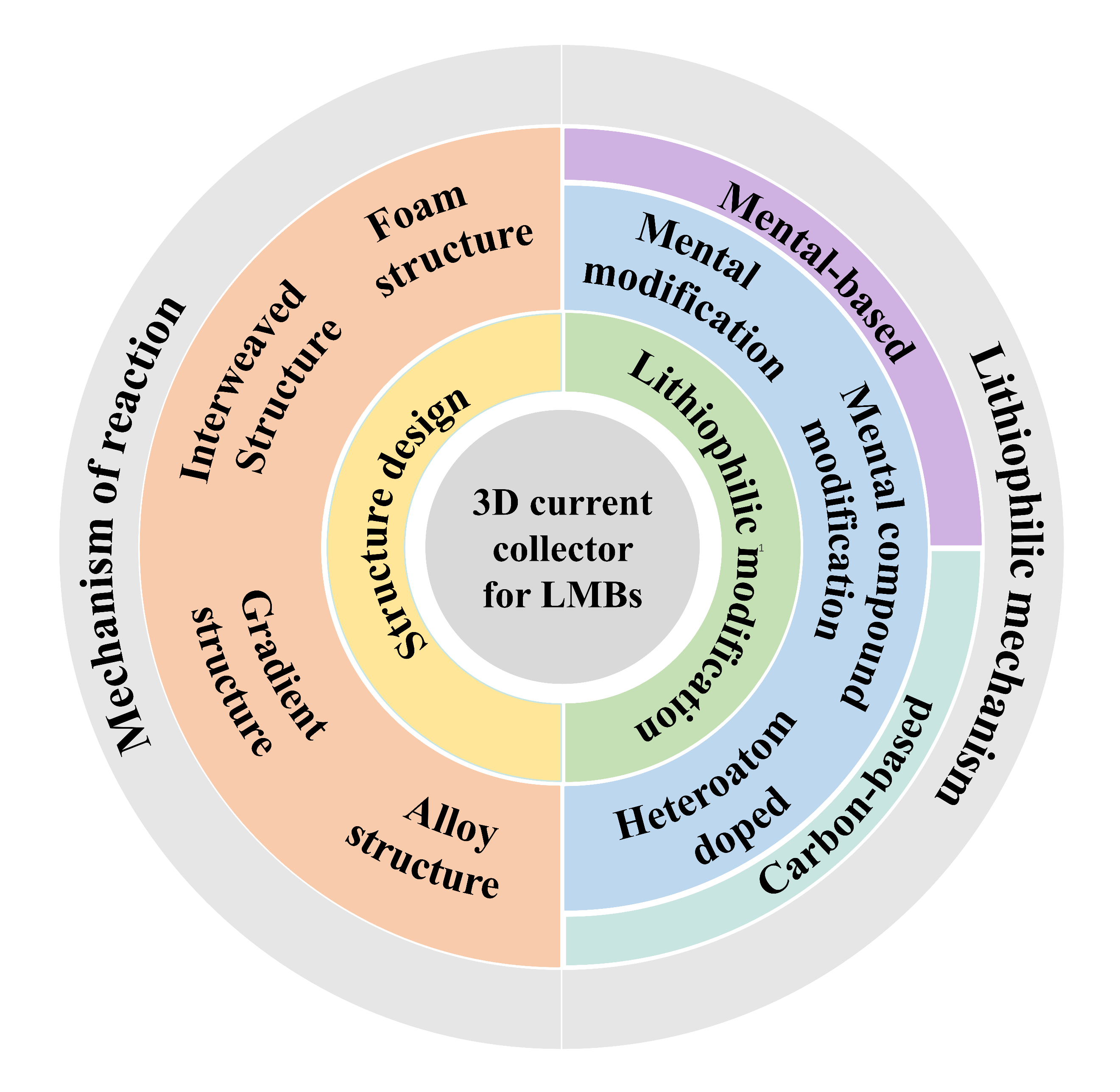
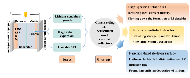
Lithium metal is considered to be the most promising anode material owing to its extraordinary theoretical specific capacity and the lowest redox potential. However, lithium anodes suffer from many challenges, such as the uncontrolled growth of lithium dendrites, unstable solid electrolyte interface (SEI) layers, and infinite volume expansion of lithium during cycling, which hinder the further commercial application of lithium metal batteries. Numerous important strategies have been proposed to overcome these challenges. Among them, three-dimensional current collectors can not only reduce the local current density and alleviate dendrite growth, but also mitigate the volume change of Li metal during the stripping/plating process. Based on the above problems, this review summarizes the working mechanisms and the latest research progress about the design of the three-dimensional structure and the lithiophilic modification to stabilize the lithium metal anode.

Contents

1 Introduction

2 The design of three-dimensional current collector

2.1 Mechanism of action

2.2 Construction methods

2.3 Structural design

3 Lithiophilic modification

3.1 Lithiophilic mechanism

3.2 Surface modification methods

3.3 Metal-based current collectors

3.4 Carbon-based current collectors

4 Conclusion and outlook

Cite this article

Chenyang Li , Li Su , Qinglei Wang , Xuehui Shangguan , Lijun Gao , Faqiang Li . Research on Construction of Three-Dimensional Current Collector for Stabling Lithium Metal Anodes[J]. Progress in Chemistry, 2024 , 36(12) : 1929 -1943 . DOI: 10.7536/PC240317

1 Introduction

The limited natural resources force people to develop alternative, environmentally friendly, and sustainable new energy sources, such as wind, water, and solar energy[1]. Rechargeable batteries, which can effectively store and release energy, are ideal for sustainable new energy. The successful commercialization of lithium-ion batteries has accelerated the rapid industrialization of portable electronics, electric vehicles, and smart grids. However, the conventional battery setup currently using graphite as the anode and transition metal oxides as the cathode cannot meet the demand for higher energy density. Therefore, there is an urgent need to develop new battery systems with higher theoretical capacity[2-3].
Lithium metal has an ultra-high theoretical specific capacity (3860 mAh·g-1) and the lowest redox potential (-3.04 V vs standard hydrogen electrode), making it stand out as an anode material for batteries[4,5]. When lithium metal anodes are paired with cathode materials, they exhibit higher energy densities compared to traditional lithium-ion batteries; for example, the theoretical specific energies of Li-S batteries and Li-O2 batteries are as high as 2600 and 11400 Wh·kg-1, respectively. Therefore, lithium metal batteries are the most promising candidates to replace lithium-ion batteries and become the next generation of high-energy-density batteries[6-7].
In fact, metal lithium was used as the anode in the early stages of lithium battery research. In 1976, Whittingham et al. from Exxon[8]used TiS2as the cathode and metal lithium as the anode to prepare the first viable lithium metal battery. Subsequently, Moli Energy in Canada commercialized lithium metal batteries on a large scale using MoS2cathodes and excess lithium. However, this battery system was abandoned due to serious safety issues, which were caused by the following problems with the lithium anode: (1) Growth of lithium dendrites. When metal lithium is directly used as the anode, uneven deposition of lithium during cycling leads to rapid nucleation and growth of lithium dendrites. Large dendrites can pierce the separator, causing short circuits and leading to severe safety issues such as fires and explosions[9].(2) Unstable solid electrolyte interphase (SEI) layer. The high reactivity of lithium metal may cause continuous side reactions inside the battery, leading to an unstable SEI layer on the surface of the lithium metal anode. The SEI layer undergoes a repetitive process of cracking, breakdown, and reconstruction. This irreversible reaction results in the continuous consumption of lithium metal and electrolyte, ultimately leading to a continuous decrease in battery capacity and accelerating battery failure. (3) Significant volume changes. As a "hostless" anode material[10-11],lithium deposition and storage do not occur within the internal structure of the lithium metal anode but tend to deposit irregularly and directionally on the surface, leading to significant and uncontrollable volume expansion. This can cause the detachment of active material during repeated deposition/stripping processes, severely affecting the Coulombic efficiency and cycle life of lithium metal batteries.
Researchers have proposed some important methods, such as constructing an artificial SEI layer[12], developing solid-state electrolytes[13-14], and modifying the electrode surface and electrolyte[15] to enhance the stability and safety of lithium anodes. Among these, using a three-dimensional (3D) porous current collector as the main body for the lithium metal anode is one of the most effective strategies. 3D frameworks possess a high specific surface area, which can uniformly distribute the diffusion flux of lithium ions on the electrode surface, effectively reducing the local current density on the electrode surface, thereby inhibiting the growth of lithium dendrites. At the same time, the interconnected 3D porous structure has advantages such as good chemical stability and high mechanical strength, providing accommodation space for lithium, restricting its deposition behavior, and alleviating the volume expansion of lithium during charging and discharging. In addition, by functionalizing the surface modification, introducing lithiophilic materials on the surface of the 3D current collector can lower the nucleation barrier, promoting uniform nucleation and dense deposition of lithium, or construct components of a stable SEI layer on the surface, accelerating the transmission of ions/electrons, thus greatly improving the cycle life of the battery system[16-17]. Compared with other strategies, 3D current collectors can simultaneously alleviate volume changes and inhibit dendrite growth, and functional surface modifications effectively guide uniform lithium deposition and stripping, offering significant advantages in enhancing the cycle life of lithium anodes. Therefore, the construction of 3D current collectors has become a research hotspot in stabilizing lithium anodes in recent years (Figure 1).
图1 锂负极在锂金属电池中存在的问题及三维结构化集流体作为锂负极载体的作用机制

Fig. 1 Issues of Li anode in Li metal batteries and the working mechanisms of 3D-structured current collectors as lithium anode hosts

This paper addresses the issues with lithium metal anodes, first analyzing the mechanisms by which two strategies—three-dimensional current collector structure design and lithiophilic modification—are used to stabilize the lithium anode. It then introduces methods for constructing three-dimensional current collectors and for surface lithiophilic modification, and reviews the latest research achievements and progress in their application in lithium metal batteries. Finally, it looks forward to future research directions for three-dimensional current collectors aimed at high-performance lithium metal anodes.

2 3D Current Collector Design

2.1 Mechanism of Action

Compared with traditional two-dimensional planar materials such as copper foil, three-dimensional current collectors have unique spatial structures and rich structural diversity, mainly stabilizing the lithium metal anode through three aspects: reducing the effective surface current density, confining lithium deposition behavior, and homogenizing the electric field distribution and lithium ion flux, thereby further enhancing the electrochemical performance.
Three-dimensional structures can increase the specific surface area of the current collector and reduce the local current density. According to the "Sand’s time" model[18-19]:
$\tau =\pi D{{\left( \frac{{{C}_{0}}e}{2J} \right)}^{2}}{{\left( \frac{{{\mu }_{a}}\begin{matrix} +{{\mu }_{Li}} \\\end{matrix}}{\begin{matrix} {{\mu }_{a}} \\\end{matrix}} \right)}^{2}}$
where τis the time when the ion concentration on the anode surface drops to zero and lithium dendrites begin to grow, Dis the diffusion coefficient, C 0is the initial lithium ion concentration, eis the electronic charge, Jis the current density, μaand μ Liare the mobilities of the anion and lithium ion, respectively. From equation (1), it can be seen that when the current density Jis infinitely small, the critical time τfor lithium dendrite growth will be infinitely extended, theoretically achieving a dendrite-free lithium metal anode. Compared with planar current collectors, three-dimensional conductive frameworks have a higher electroactive specific surface area, which is beneficial for reducing local current density and effectively prolonging the time for dendrite formation, thereby suppressing the growth of lithium dendrites. At the same time, the porous structure can also provide accommodation space for lithium, limiting the deposition behavior of lithium, alleviating the volume changes during the lithium deposition/stripping process, and improving the safety performance of the battery. For example, Yang et al. [20]used a chemical dealloying method to completely dissolve Zn from a Cu-Zn alloy strip to prepare a three-dimensionally interconnected porous copper current collector, as shown in Figure 2a. This structure provides large internal voids for the deposition of metallic lithium, restricts the volumetric expansion of lithium, effectively inhibits dendrite growth, and reduces the formation of dead lithium, thus obtaining a stable electrode structure and SEI layer.
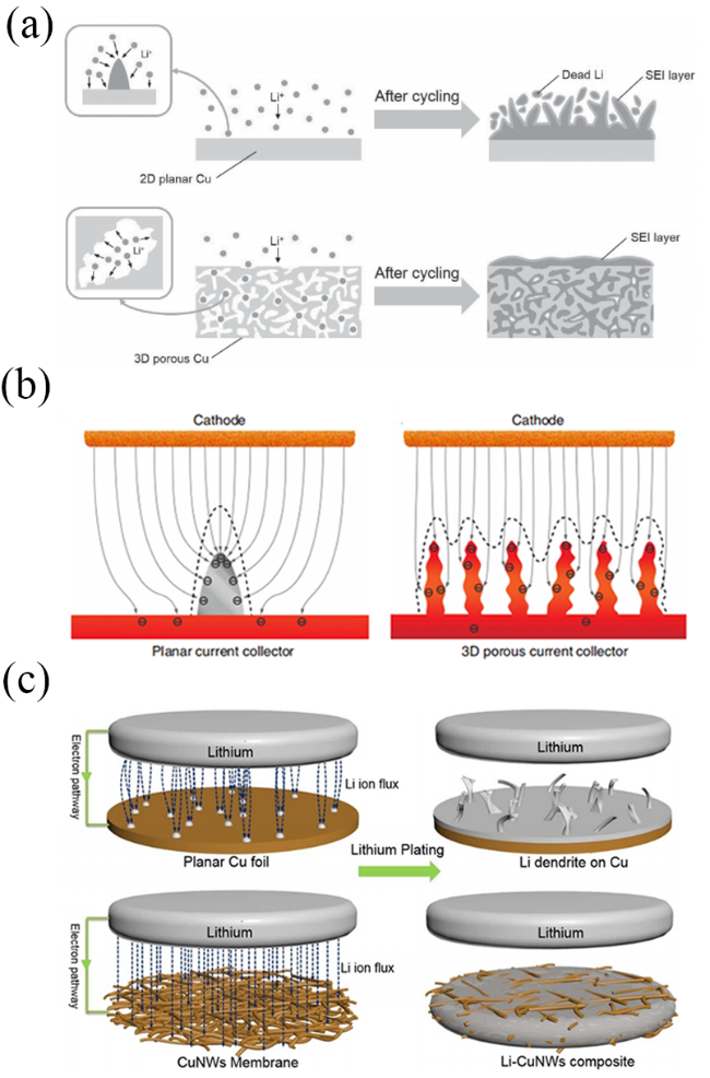
图2 (a) 二维平面铜和三维多孔铜上锂沉积的结构变化示意图[20];(b) 平面和多孔铜箔上的电场以及相应的锂沉积位点示意图[21];(c) 平面铜箔和铜纳米线膜之间的锂离子通量分布和锂沉积模型的明显差异概要[22]

Fig. 2 (a) Schematic of structural changes in depositing Li on 2D planar Cu and 3D porous Cu[20]. (b) Schematic of the electric field on planar and porous copper foils and the corresponding Li deposition sites[21]. (c) Synopsis of obvious difference of Li-ion flux distribution and Li plating models between planar Cu foil and Cu nanowire membrane[22]

In addition, three-dimensional porous structures can also play a role in homogenizing the electric field, charge distribution, and lithium ion diffusion flux on the electrode surface. On a two-dimensional planar substrate, lithium tends to form small dendrites first on smooth surfaces during nucleation. When charges accumulate at the tips in the electric field, the previously deposited small lithium dendrites act as charge centers, and then lithium deposits at the ends of the dendrites, leading to rapid growth of lithium dendrites, which can easily cause battery short circuits.
and the three-dimensional structure can uniformly distribute the electric field, inducing uniform deposition of lithium ions. Guo et al.[21]prepared a 3D copper foil with submicron skeletons by reducing in-situ grown Cu(OH)2to Cu, as shown in Figure 2b. The protruding tips on the fibers act as charge centers and nucleation sites, dispersing charges and electric fields, effectively regulating the uniform deposition of lithium ions. Yu et al.[22]designed a freestanding copper nanowire network current collector. On planar copper foil, the lithium ion flux concentrates at the cracks in the SEI film, and during subsequent lithium plating, the concentrated lithium ion flux accelerates the growth of lithium dendrites at the crack points. In contrast, the high surface area interconnected copper nanowire network ensures a uniform distribution of lithium ion flux on the electrode surface, promoting uniform lithium plating (Figure 2c).

2.2 Construction Method

Designing and preparing three-dimensional current collectors with specific structures plays a crucial role in achieving uniform and controllable lithium deposition. The synthesis methods of three-dimensional current collectors mainly include electrospinning, templating, dealloying, and high-temperature carbonization. Table 1 summarizes the advantages and disadvantages of these four three-dimensional current collector synthesis methods.
表1 四种三维集流体合成方法的优点和缺点

Table 1 Advantages and disadvantages of four synthesis methods of the three-dimensional current collector

Methods Advantages Disadvantages
Electrospinning Controllable and tunable fiber features; good scalability; simple operation; low cost Highly corrosive or toxic solvents used for preparing the spin solution; difficulty in recycling; causing environmental pollution easily
Templating Controllable fiber features Complex operation process; high cost, time-consuming, difficulty in removing templates
Dealloying Simple operation; low cost; easy mass production Uncontrollable porous nanometal materials features
High-temperature carbonization Simple operation; low cost making the material brittle
Electrospinning is a technology for preparing nanofibers from polymer solutions under high-voltage electrostatic conditions, and the nanofibers produced have characteristics such as large specific surface area, high porosity, easy control of size, and easy surface functionalization. Li et al.[23] prepared a Zn, O, N co-doped carbon fiber (ZON-CF) using electrospinning and high-temperature carbonization methods, which was used as a skeleton for loading metallic lithium. The hierarchical porous structure composed of macropores between carbon fiber networks and mesopores within individual fibers can accommodate volume changes during the lithium deposition/stripping process. In addition, the incorporated Zn forms a Li-Zn alloy during the lithium deposition process, which can serve as an active site for lithium nucleation, effectively regulating the lithium deposition behavior. By using a template method, templates with specific structures and shapes can be selected and designed to obtain porous structures with defined pore sizes and porosities. Cui et al.[24] used spiky nickel powder as a template to prepare wrinkled graphene cage carriers (WGC) containing gold nanoparticles inside, exhibiting good mechanical stability and lithium ion conductivity. Additionally, dealloying is also one of the common methods for constructing three-dimensional porous current collectors, referring to selectively dissolving one or several more reactive elements in an alloy, making the alloy unstable, and the remaining less reactive metal atoms rearrange to form a porous network structure.
Through the above synthesis methods, 3D current collectors with different structures can be designed, such as foam structure, interwoven structure, gradient structure, and alloy structure, thereby addressing the issues present in lithium metal batteries during cycling. The following will focus on the preparation of these four types of structured current collectors and the stabilization of the metallic lithium anode.

2.3 Structural Design

2.3.1 Foam Structure

The porosity of the current collector is very important for addressing the volume expansion problem of metallic lithium during cycling, hence a large number of studies have used current collectors with porous structures as lithium metal anodes. These include various metal foams, dealloyed porous materials, and metal meshes. Metal foams[25-27], such as copper, nickel, and titanium foams, possess advantages like high structural stability, large surface area, and good electrical conductivity, and are widely used as current collector materials. Li et al.[27] prepared nanoporous nickel foam with a large surface area and surface defects through a redox method (Figure 3a). The macroporous structure of this skeleton can partially accommodate volume changes, while well-distributed nanopores can effectively reduce local current density, promote uniform distribution of lithium ion flux, and regulate uniform lithium nucleation and deposition.
图3 (a) 纯泡沫Ni和纳米多孔泡沫Ni集流体上锂沉积行为示意图[27];(b) 三维导电Ti3C2Tx-MXene-三聚氰胺泡沫的制备过程示意图[30]

Fig. 3 (a) Schematics of Li deposition behavior on pure Ni foam and nanoporous Ni foam CCs[27]. (b) Schematic illustration of the fabrication process of the 3D conductive Ti3C2Tx MXene-melamine foam[30]

In addition to metal foams, graphene foams[28], melamine foams[29] have also been used as lithium anode hosts. For example, Wu et al.[30] prepared a 3D conductive Ti3C2Tx-MXene-melamine foam (MXene-MF) (Figure 3b). Thanks to the high conductivity of MXene and the good lithiophilicity of fluorine terminations, as well as the porous, lightweight, and excellent mechanical toughness of melamine foam, the resulting MXene-MF possesses a 3D porous conductive network structure and good mechanical strength, enabling highly dense and uniform lithium deposition, with good cycling life even at a high current density of 50 mA·m−2 and a high deposition capacity of 50 mAh·cm−2.

2.3.2 Interleaved Structure

Interwoven 3D current collectors are formed by the interweaving of one-dimensional materials, such as metal meshes[31-32], freestanding frameworks composed of metal nanowires[33-34], or three-dimensional disordered network structures interconnected by carbon nanotubes and carbon fibers[35], etc., which can effectively alleviate the volume changes of lithium.
Zhang et al.[31]used the method of ammonia oxidation to modify lithiophilic CuO and SnO2onto a commercial bronze mesh, serving as a lithium anode carrier. By mechanically pressing this carrier with lithium, a composite anode (3D CSM/Li) was prepared. The bronze mesh has a robust framework, and the lithiophilic CuO and SnO2interfaces can optimize the SEI layer and reduce overpotential, thus achieving uniform lithium plating. The heavy metal current collector correspondingly limits the mass/volume energy density of lithium metal batteries. Therefore, researchers have designed the use of high-aspect-ratio metal nanowires as the host for lithium metal anodes. Yang et al.[36]designed a self-supporting conductive nickel nanowire mesh framework coated with Li2O (Ni@Li2O-NW) (Figure 4). In this, the nanostructured nickel framework serves as a conductive network, while the thin dielectric and lithium-ion conductive Li2O coating not only helps in forming a uniformly distributed internal electric field but also acts as a quasi-SEI layer and promotes lithium ion transport, thereby inducing uniform deposition of lithium ions.
图4 基于Ni-NW和Ni@Li2O-NW集流体的循环前后的示意图[36]

Fig. 4 Schematic illustrations of different anodes before and after cycling based on Ni-NW and Ni@Li2O-NW current collectors[36]

2.3.3 Gradient Structure

It is well known that the lithium deposition pattern is crucial in determining the cycling stability and safety of batteries. In conductive three-dimensional porous frameworks, lithium preferentially deposits at the top, leading to uneven deposition and easy formation of lithium dendrites, ultimately causing a short circuit in the battery, a phenomenon commonly referred to as the "top growth" mode. However, constructing three-dimensional current collectors with gradient structures[37] can achieve bottom-up growth of lithium. Ai et al.[38] grew CuO nanowires on copper foils using electrochemical methods, producing a series of 3D integrated gradient copper current collectors with varying degrees of dispersion, by adjusting the dispersity of the nanowire arrays to control their interfacial structure. The study showed that interface structures composed of both sparse and densely distributed CuO nanowire arrays were unfavorable for the nucleation and deposition of lithium, leading to rapid dendrite growth. In contrast, uniformly and appropriately dispersed nanowire arrays (M-CuO@Cu) enabled stable and uniform nucleation of lithium metal at the bottom, with lateral deposition of lithium at the bottom, thus providing an ideal bottom-up lithium growth pattern (Figure 5a). The M-CuO@Cu electrode could stably cycle for 1200 h under testing conditions of 1 mA·cm−2, 1 mAh·cm−2. Moreover, the assembled pouch cell had a specific capacity of 120 mAh·g−1 after 70 cycles at 0.5 C, with a capacity retention rate as high as 99.4%, capable of continuously driving a 3 V electric fan, demonstrating excellent practicality and compatibility. Liu et al.[39] used a solution combustion method to deposit ZnO with different contents onto copper foam to construct a gradient lithiophilic framework (GSZO-CF) (Figure 5b), where the content of lithiophilic Zn increased from top to bottom, inducing preferential deposition of lithium within the copper foam, and the graded lithium ion transport barrier and ionic conductivity allowed for uniform regulation of lithium ions, achieving even deposition of lithium, further suppressing the formation of lithium dendrites and dead lithium. Even under ultra-high current density of 50 mA·cm−2 and high capacity of 10 mAh·cm−2, the symmetric cell could still stably cycle over 800 cycles (Figure 5c). Similar to metal-based skeletons, carbon structures can also serve as the main body of gradient skeletons. To suppress the growth of lithium dendrites, Kang et al.[40] designed a dual-gradient ultra-light carbon nanofiber skeleton (CBG) (Figure 5d). The dual gradients included a top-down ZnO gradient and a bottom-up Sn gradient prepared by magnetron sputtering. Before lithium deposition, ZnO reacted with lithium ions to form Li-Zn alloys and Li2O, endowing the carbon framework with a higher lithium ion diffusion coefficient, accelerating the transmission of lithium ions. Meanwhile, the bottom Sn, with good electrical conductivity and strong lithiophilicity, greatly reduced the overpotential for lithium nucleation, guiding the preferential deposition of lithium at the bottom. Additionally, a carbon nanotube-interwoven polyhedron (CNIP) evolved from a ZIF-8@ZIF-67 core-shell framework also formed a lithiophilic gradient from inside out (Figure 5e)[41]. Lithiophilic ZnO concentrated within the carbon polyhedra induced the preferential nucleation and inside-out deposition of metallic lithium. Simultaneously, the hollow carbon nanotube network, with its excellent electronic conductivity, provided dual continuous channels for lithium ions and electrons, effectively inhibiting the growth of lithium dendrites and maximizing the spatial utilization of the polyhedra.
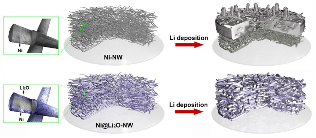
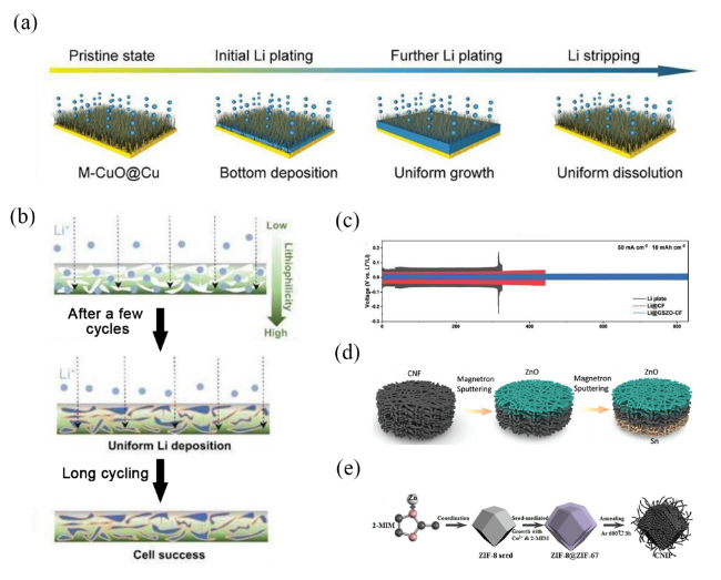
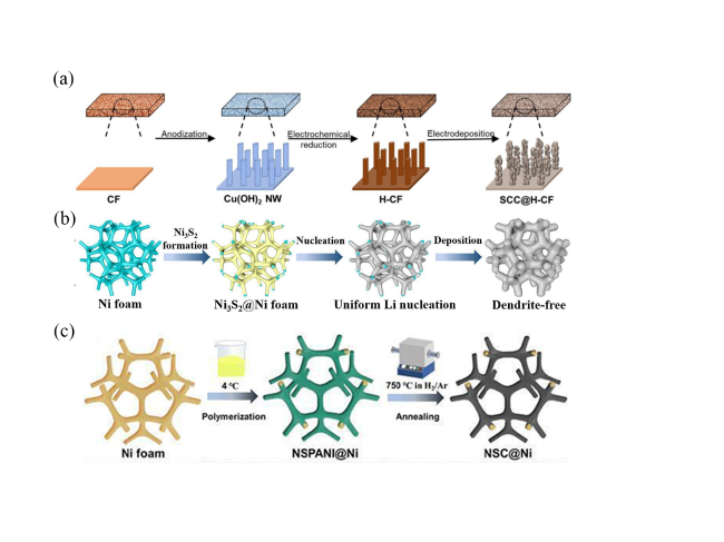
图5 (a) M-CuO@Cu电极上锂沉积模式的示意图[38];(b) GSZO-CF基材上的锂电镀工艺示意图[39];(c) GSZO-CF对称电池的电化学性能:50 mA·cm−2 电流密度,10 mAh·cm−2 锂固定沉积量下[39];(d) CBG合成过程示意图[40];(e) CNIP 纳米复合材料合成过程的机理示意图[41]

Fig. 5 (a) Schematic illustration of the Li deposition patterns on M-CuO@Cu[38]. (b) Schematic illustration of Li plating process on GSZO-CF[39]. c)Electrochemical performance of symmetric cells[39] at 50 mA·cm−2 with a fixed Li deposition of 10 mAh·cm−2. (d) Schematic illustration of the synthesis procedure of CBG[40]. (e) Mechanism schematic of the CNIP nanocomposite synthesis process[41]

2.3.4 Alloy Structure

Alloying in three-dimensional current collectors not only reduces the activity of lithium metal, thereby reducing its reactivity with the electrolyte, but also lowers the nucleation overpotential of metallic lithium, thus effectively inhibiting the formation of lithium dendrites. Therefore, alloy-structured current collectors have been widely studied to improve the performance of lithium anodes, such as lithium-magnesium alloys, lithium-indium alloys, lithium-tin alloys[42], and lithium-silicon alloys[43].
Wu et al.[44]prepared a multi-component alloy composite framework through a simple two-step preparation method, obtaining a composite alloy anode (Li-Mg-Ca) by melting, rolling, and heat treatment, which can form uniformly distributed nucleation sites, uniform lithium ion flux, and reduce local current density to inhibit the growth of lithium dendrites (Figure 6a). The Li-Mg-Ca electrode exhibits excellent mechanical properties, thermal stability, interfacial stability, and electrochemical stability. The Li-Mg-Ca alloy electrode can stably cycle for 1000 h at a current density of 2 mA·cm−2and an areal capacity of 4 mAh·cm−2. The assembled practical pouch cell with an energy density of 350 Wh·kg−1works well and can meet the energy demands of electronic devices. Wang et al.[45]prepared a nano-level uniformly distributed Li-Al alloy composite anode (NLA20, where the mass content of Al is 20 %) using an in-situ lithiothermic reduction method (Figure 6b). Compared to pure lithium anodes, the in-situ formed lithium aluminum alloy is uniformly distributed in the lithium anode, providing fast ion diffusion channels, reducing the nucleation potential of lithium, inducing uniform lithium deposition, and also suppressing side reactions at high temperatures. In symmetric cell tests, the NLA20 electrode exhibited an extremely low overpotential of 5 mV and ultra-long cycle life at 60 ℃.
图6 (a) 锂箔与Mg-Ca合金骨架上锂成核和生长过程示意图[44];(b)循环过程中NLA-20和纯锂箔上锂沉积行为示意图[45]

Fig. 6 (a) Schematic diagrams of the Li nucleation and growth process on the bare Li foil and Mg-Ca alloy skeleton[44];(b) Schematics of Li deposition behavior on NLA-20 and bare Li foil[45]

3 Lithiophilic Modification

By introducing a large number of uniformly dispersed lithiophilic sites on the anode surface, uniform lithium ion flux and electric field can be guided, reducing local current density and regulating the nucleation and deposition/stripping behavior of lithium. However, original three-dimensional current collectors are mostly lithiophobic, unable to guide the uniform distribution of lithium and highly prone to the formation of lithium dendrites. Therefore, the substrate can be modified with lithiophilic materials to improve lithiophilicity. This chapter first elucidates the mechanism of lithiophilization, and then summarizes the research progress in recent years on the modification of metal-based and carbon-based three-dimensional current collectors for enhanced lithiophilicity.

3.1 Lithiophilic Mechanism

Lithiophilicity refers to the affinity or wettability of a material for lithium deposition. Guo et al[46]pointed out through experiments that the improvement in wettability is mainly attributed to the formation of new chemical bonds between molten lithium and lithiophilic substances, and further calculated the Gibbs free energy of formation (Δr G) for reactions between molten lithium and various elements in the periodic table (Figure 7a). Typically, a negative Δr Gfor a specific reaction indicates the formation of new chemical bonds, thereby enhancing the wettability of molten lithium. This provides a theoretical basis for regulating the wettability of current collectors.
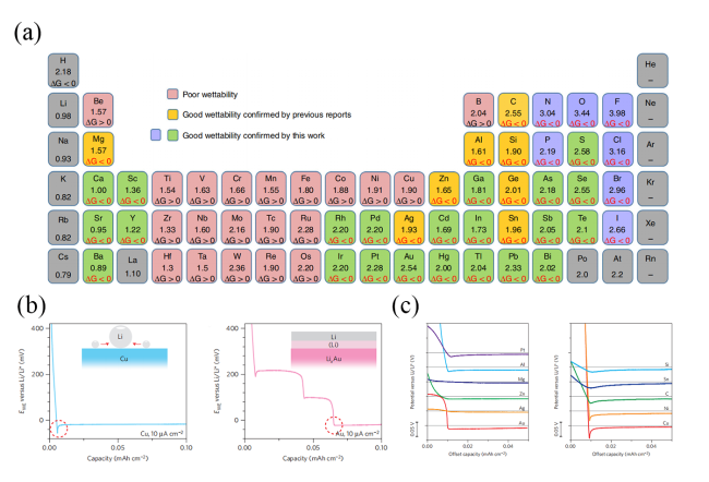
图7 (a) 元素周期表中各种元素的电负性以及与锂反应的元素或化合物的吉布斯自由能变[46];(b) 铜箔和金基底上锂镀层的成核过电势[47];(c) 各种基底上锂成核过电势的比较[47]

Fig. 7 (a) Electronegativities of various elements in the periodic table and ΔrG of elements or compounds reacted with the molten Li[46]. (b) Nucleation overpotential of Li plating on Cu foil and Au substrate[47]. (c) Comparison of Li nucleation overpotential on various substrates[47]

The voltage curve of lithium plating on the substrate exhibits a distinct voltage plateau and a sudden drop in voltage. The nucleation overpotential is defined as the difference between the peak voltage and the subsequent stable mass transfer-controlled overpotential, which can be used to quantitatively evaluate the lithiophilicity of the electrode surface. Cui et al.[47] studied the nucleation barriers of lithium on various substrates, as shown in Figure 7b, where the nucleation overpotential of lithium on a Cu substrate is about 40 mV, required to overcome the heteronucleation barrier due to the large thermodynamic mismatch between lithium and Cu. In contrast, Au can react with lithium to form multiple LixAu alloy phases and has a certain solubility in lithium metal. The resulting solid solution surface layer has the same crystal structure as pure lithium metal and can serve as a buffer layer for subsequent lithium deposition. Therefore, the nucleation overpotential of lithium on Au is essentially zero. They further investigated the overpotentials of other substrates during the lithium nucleation process, as illustrated in Figure 7c. Metals with high solubility in lithium (Au, Ag, Zn, Mg) exhibit zero overpotential, those with relatively low solubility (Al, Pt) show small but observable overpotentials, and substrates that do not dissolve in lithium (Cu, Si, Sn, Ni, C) display significant lithium nucleation overpotentials.

3.2 Surface Modification Methods

The main methods for lithiophilic modification of three-dimensional current collectors include chemical vapor deposition, magnetron sputtering, and in-situ chemical reaction methods.
Chemical vapor deposition is a technique for directly growing ultra-thin films on electrodes at high temperatures through the chemical action of precursors, and it can be used to achieve highly uniform and stable atomic layer protective films on metallic lithium. Du et al.[48] combined atomic layer deposition and chemical vapor deposition to encapsulate ultra-thin MgF2 nanosheets within nitrogen-doped graphene-like hollow nanospheres (MgF2 NSs@NGHSs). The uniform and continuous Li-Mg solid solution inner layer formed by the MgF2 nanosheets can reduce the nucleation overpotential and induce selective Li deposition into the cavities of NGHS, thereby greatly alleviating the growth of lithium dendrites and volume changes.
Magnetron sputtering is a technique that uses magnetic fields and the sputtering process to deposit thin films, which can utilize the magnetic field to suppress the movement of electron ionization rates, thereby precisely controlling the position of the sputtered material. Therefore, it has been widely used for depositing metal particles on various three-dimensional porous structures. For example, Winter et al[49] used magnetron sputtering technology to directly coat lithiophilic Zn, Au on the surface of copper current collectors, forming Li-Zn alloys and Li-Au alloys respectively during the deposition of metallic lithium, thus guiding the uniform deposition/stripping of lithium.
In-situ chemical reactions refer to the process where some lithiumophilic or other functional atoms or nanoparticles can grow onto a 3D current collector through in-situ reactions. Han et al.[50] grew N-doped carbon nanotubes on the surface of nickel foam using an in-situ growth method, forming a 3D current collector (NCNT/NF) with a multi-level lithiumophilic structure. This framework exhibits excellent flexibility, and the introduction of pyridinic N provides a large number of nucleation sites, effectively improving the lithium affinity of the matrix.

3.3 Metal-Based Current Collectors

Metal-based materials, with advantages such as high mechanical strength, good electrical conductivity, low cost, and a relatively wide electrochemical window, have been widely studied in lithium metal anodes. However, most metals have poor affinity for lithium, making it necessary to further improve electrochemical performance through lithiophilic modification. For metal-based materials, common types of surface modifications mainly include metal nanostructure decoration and heteroatom-doped carbon coating.

3.3.1 Metal Nanostructure Modification

Combining three-dimensional metal current collectors with lithiophilic nanomaterials, utilizing the synergistic effect between the two, can achieve stable lithium metal anodes, thereby enhancing battery performance. Due to the poor plasticity of metal-based materials, the common three-dimensional structures of metal-based materials are mostly foam-like, mesh-like, and nanowires, Table 2 summarizes some studies on using lithiophilic metal nanostructures to modify copper foam and nickel foam current collectors, as well as their performance in symmetric cells. Firstly, using copper foam as a three-dimensional current collector, modifying its surface with lithiophilic nanomaterials such as ZnO nanosheets[51], Cu nanowires[52], Cu2O nanowires[53], CuS2 nanowires[54], etc., can induce uniform nucleation of lithium, achieving uniform electroplating of metallic lithium. Recently, Choi et al.[55] grew hierarchical Cu2+1O nanowires on the surface of copper foam via wet chemical methods and further modified the surface of the nanowires with an ultrathin and uniform layer of Sn/Cu6Sn5 composite material (SCC@H-CF) (Figure 8a), which can reduce the nucleation barrier for lithium, inducing uniform nucleation; the large surface area of Cu2+1O nanowires can lower the local current density to evenly distribute surface charge, thus further achieving uniform deposition of lithium. During testing, the symmetric cell could stably cycle for over 3000 hours at a current density of 0.5 mA·cm−2, with a voltage hysteresis maintained at 8 mV. Moreover, when matched with a LiFePO4 cathode, the assembled full cell exhibited excellent cycling stability and rate capability. Similar to the above-mentioned lithiophilic modification strategies, our team[56] vertically grew hierarchical Cu fibers on copper foam as a lithiophilic scaffold (HCF/CF). The secondary protrusion structure on the surface of the Cu fibers serves as charge centers and electrochemical sites, inducing uniform nucleation and growth of lithium. The excellent mechanical strength of HCF/CF ensures that the composite lithium anode has high structural stability during rapid and repetitive lithium plating/stripping processes. Compared to copper foam, the HCF/CF scaffold shows significantly improved lithium plating/stripping behavior, maintaining a high Coulombic efficiency of 98% over 200 cycles. To promote the practical application of lithium metal batteries, we will explore their use in pouch cells in future research.
表2 利用亲锂金属纳米结构修饰泡沫铜和泡沫镍的方法和性能参数

Table 2 Methods and performance parameters of modifying copper foam by lithiophilic metal nanostructures

substrate Lithiophilic materials Cycling condition Cycle performance/(h) Overpotential/(mV) Ref
Cu foam ZnO Nanoflakes (1mA·cm−2, 1mAh·cm−2) 4000 13 51
3D Li2O@Cu nanowires array (1mA·cm−2, 1mAh·cm−2) 600 15 52
Li2O@Cu nanowires array (1mA·cm−2, 1mAh·cm−2) 500 10 53
Cu2S NWs (1mA·cm−2, 1mAh·cm−2) 150 50 54
Cu6Sn5@Cu2+1O nanowires (1mA·cm−2, 1mAh·cm−2) 1250 8 55
Ni foam ZnO nanorods (1mA·cm−2, 2mAh·cm−2) 1200 12 57
NiFx nanosheets (1mA·cm−2, 1mAh·cm−2) 1300 20 58
V2O5 nanobelt arrays (1mA·cm−2, 1mAh·cm−2) 1600 18 59
Hierarchical Oα-rich Co3O4 nanoarray (1mA·cm−2, 1mAh·cm−2) 800 32 60
Lithiated NiCo2O4 Nanorods (1mA·cm−2, 1mAh·cm−2) 1000 16 61
Ni3S2 layer (1mA·cm−2, 1mAh·cm−2) 1000 25 62
图8 (a) CF 中 SCC@H-CF的示意图[55];(b) Ni3S2@Ni 泡沫上的锂沉积/剥离行为示意图[62];(c) NSC@Ni 的合成过程示意图[63]

Fig. 8 (a) Schematic diagram of SCC@H-CF from CF[55]. (b) Schematic illustration of the Li plating/stripping behavior on Ni3S2@Ni foam[62]. (c) Schematic of the synthesis process of NSC@Ni[63]

In addition, using nickel foam as a three-dimensional current collector, preparing lithium-philic ZnO nanorods[57], NiFx nanosheets[58], V2O5 nanoribbon arrays[59], Co3O4 nanoarrays[60], and NiCo2O4 nanorods[61] on its surface can inhibit the growth of lithium dendrites and form a stable SEI film. Nan et al.[62] synthesized a Ni3S2 layer with excellent lithium affinity (Figure 8b) on nickel foam, which can provide abundant nucleation sites to induce uniform lithium nucleation. Furthermore, Ni3S2 reacts in situ with metallic lithium to form Li2S, creating a uniform SEI film that effectively regulates lithium ion flux and achieves rapid ion transport.

3.3.2 Heteroatom-Doped Carbon Coating

Modifying metal current collectors with heteroatom-doped carbon coating is also an effective strategy to enhance their lithiophilicity. Liu et al.[63] prepared 3D nickel foam modified by N, S co-doped carbon using an interfacial polymerization method, which was used as a lithium metal host (NSC@Ni) (Figure 8c). The N, S co-doped carbon significantly enhanced the lithiophilicity of the skeleton, allowing for rapid injection of molten lithium into the skeleton to form the NSC@Ni-Li composite lithium anode. During the molten infusion process, in-situ formed Li3N and Li2S layers with high lithium ionic conductivity, and the strong interaction between metallic lithium and N, S co-doped carbon helped regulate the lithium ion flux and reduce the nucleation barrier of lithium, ultimately inhibiting the growth of lithium dendrites.

3.4 Carbon-Based Current Collectors

Carbon materials as three-dimensional current collectors for stabilizing metallic lithium anodes have many advantages, such as abundant sources, low density, light weight, high electrical conductivity, chemical stability, and ease of functionalization and surface modification. However, carbon materials have poor affinity for lithium, leading to a high nucleation barrier for lithium deposition. Therefore, effective methods such as heteroatom doping, metal nanoparticle and metal compound decoration can be used to enhance their lithiophilicity, thereby inducing lithium nucleation and promoting uniform lithium deposition.

3.4.1 Heteroatom Doping

Negatively charged heteroatoms (such as B, N, O, S, P, etc.) have strong interactions with positively charged lithium ions, making heteroatom doping an effective strategy for enhancing the lithiophilicity of carbon materials. Zhang et al.[64] summarized the calculated binding energies between various heteroatom-doped carbons and lithium atoms (Figure 9a). Zhang et al.[65] investigated the application of nitrogen-doped graphene (NG) in lithium metal anodes, revealing the impact of different nitrogen functional groups on the uniform nucleation of lithium and the lithiophilic nature of nitrogen (Figure 9b). The overpotential of lithium plating on copper foil and NG electrodes was experimentally explored, with the overpotential of NG being much lower than that of copper foil, indicating that the former has higher lithiophilicity (Figure 9c). Density functional theory calculations showed that, compared to graphene and copper, pyrrolic and pyridinic nitrogens have greater binding energies with lithium, at -4.46 and -4.26 eV, respectively (Figure 9d). The increased local charge density between pyrrolic nitrogen and lithium indicates a strong interaction between lithium and N atoms (Figure 9e). Pyrrolic nitrogen groups contain an extra electron, and pyridinic nitrogen groups contain lone pair electrons. Nitrogen-containing Lewis base sites strongly adsorb Lewis acidic lithium ions through acid-base interactions, guiding the uniform distribution of lithium nuclei on the anode surface. In contrast, quaternary nitrogen, with its saturated electron orbitals, cannot provide additional electrons to adsorb lithium ions, resulting in relatively low binding energy. This provides theoretical guidance for incorporating nitrogen-containing functional groups into carbon-based materials to enhance lithiophilicity.
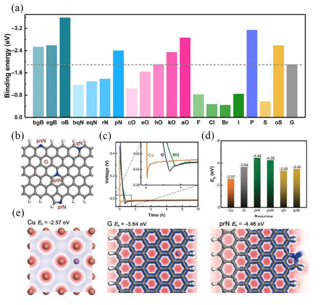
图9 (a) 杂原子掺杂碳和锂原子之间的计算结合能总结[64];(b) 锂在铜箔、石墨烯和N掺杂石墨烯电极上成核过电势[65];(c) 具有吡啶氮(pnN)、吡咯氮(prN)、边缘季氮(qN)和体相季氮(qnN)的N掺杂石墨烯的示意图[65];(d) 锂原子与Cu、石墨烯以及N掺杂石墨烯的不同官能团的结合能[65];(e) Cu、石墨烯和吡咯-N基团的锂原子吸附位点处的形变电荷密度[65]

Fig. 9 (a) Summary of calculated binding energy between heteroatom-doped carbon and a Li atom[64]. (b) Nucleation overpotential on Cu foil, graphene (G), and NG electrodes[65]. (c) Schematic diagram of N-doped graphene with pyridinic nitrogen (pnN), pyrrolic nitrogen (prN), quaternary nitrogen on the edge (qN) and quaternary nitrogen in the bulk phase (qnN)[65]. (d) Binding energy of a Li atom with Cu, G, and different functional groups of N-doped graphene[65]. (e) The deformation charge density at a Li atom adsorption site of: Cu, graphene, and pyrrolic-N group[65]

Yu et al.[66] proposed the use of carbon cloth (CC@CN-Co) modified with nitrogen-doped carbon nanosheet arrays embedded with Co nanoparticles as a 3D matrix for pre-storing lithium. Nitrogen-containing functional groups have a strong interaction with lithium, which can guide uniform nucleation of lithium, and tiny Co nanoparticles provide active sites to guide uniform deposition of lithium. Therefore, this matrix exhibits characteristics of being free from lithium dendrites and stable cycling performance. Zhang et al.[67] obtained an integrated reduced graphene oxide/carbon nanotube 3D framework rich in imine bonds (iPANI@rGO-CNTs) through the in-situ copolymerization of phytic acid and aniline. Using lithiophilic imine bonds as anchor points for strong LiPS adsorption and uniform lithium deposition, they deposited lithium on the matrix via electroplating to obtain the composite lithium metal anode Li-iPANI@rGO-CNTs, which can form a uniform electric field, thereby regulating the uniform deposition of lithium. As a result, the composite lithium anode endows the lithium-sulfur full cell with excellent rate performance and superb cycling performance. Compared to single-doping systems, dual-doping systems exhibit superior lithiophilicity. In the oxygen and boron co-doped honeycomb-like carbon skeleton (OBHcCs) electrode[68], lithiophilic oxygen and boron functional groups can reduce the lithium nucleation barrier, promoting the uniform distribution of lithium ion flux. Additionally, this skeleton has a high specific surface area, effectively reducing local current density, thus inhibiting the growth of lithium dendrites. Therefore, the OBHcCs@Li||LiFePO4 full cell shows a good capacity retention rate of 84.6% and a high coulombic efficiency of 99.6% after 500 cycles at 0.5 C.

3.4.2 Modification with Metal Nanoparticles

The introduction of metal nanoparticles into carbon materials can enhance the lithiophilicity of the skeleton, thereby inducing uniform lithium nucleation. Commonly used nanoparticles include Au[69-70], Ag, Zn[71,72], Co[73], Sn[74], Ni[75], Si[76], etc. Gao et al.[77] deposited a series of lithiophilic metal particles (CNF/Me, Me=Sn, Fe, Co) on three-dimensional self-supporting carbon nanofibers to induce lithium deposition behavior. Lithiophilic metals not only provide a large number of active sites but also enhance lithiophilicity, reducing the nucleation barrier of lithium and thus achieving uniform nucleation and deposition of lithium. Additionally, Mao et al.[78] coated lithiophilic silver nanowires onto 3D carbon cloth (Ag NWs/CC) using a vacuum filtration method (Figure 10a). The introduced silver nanowires provided uniform lithium nucleation sites and alleviated the growth of lithium dendrites.
图10 (a) Ag NWs/CC 的合成过程示意图[78];(b) CNF和Mo2C@CNF沉积锂后相应的示意图[84];(c) 金属氮化物@CF的合成过程示意图[85]

Fig. 10 (a) Schematic of the synthesis process of the Ag NWs/CC[78]. (b) Schematic diagrams of CNF and Mo2C@CNF after depositing Li[84]. (c) Schematic of the synthetic procedures of metal nitrides@CF[85]

3.4.3 Metal Compound Modification

In addition to metal nanoparticles, doping with metal compounds, such as oxides (ZnO[35,79], SnO2 [80], MnO2 [81], etc.), nitrides[82], or sulfides[83]is another method to improve the lithiophilicity of carbon-based materials, providing active sites for lithium metal and enhancing the lithium wettability of carbon materials. Recently, Peng et al.[84]decorated lithiophilic Mo2C clusters on the surface of carbon nanofibers (Mo2C@CNF). On one hand, the uniformly dispersed lithiophilic Mo2C clusters provide a large number of nucleation sites for lithium deposition and effectively reduce the nucleation barrier; on the other hand, transition metal elements act as catalysts, forming a stable and robust SEI layer containing LiF on the Mo2C@CNF, which effectively reduces the formation of dead lithium and improves the Coulombic efficiency during long-term operation (Figure 10b). The symmetric cell assembled with it can stably cycle for more than 1600 h at a current density of 1 mA·cm−2, with an overpotential of about 13 mV. Wei et al.[85]modified the carbon framework with arrays of highly lithiophilic transition metal nitrides, including CoN, VN, and Ni3N, and prepared composite lithium metal anodes by a thermal melting casting method (Figure 10c). The carbon skeleton and metal nitrides have excellent electronic conductivity, ensuring rapid electron transfer at the liquid-solid interface and providing a stable interface for lithium reduction. At the same time, the lithiophilic interconnected framework serves as a stable "nest" to store lithium metal and alleviate volume changes during cycling. In the symmetric cell test, due to the lattice matching between CoN and metallic lithium, the Li/CoN@CF composite anode can achieve stable cycling for more than 1000 h under high current densities of 20 mA·cm−2and high areal capacities of 20 mAh·cm−2, demonstrating ultra-stable cycling performance. In addition, carbon nanofibers decorated with MoS2nanosheets[86], ultrafine TiN nanoparticles[87], and Mo2N[88]also show excellent performance in stabilizing the lithium metal anode.

4 Conclusions and Future Prospects

Based on the ultra-high theoretical specific capacity and the lowest redox potential of lithium metal, lithium metal batteries have become one of the most popular energy storage devices. However, the lithium metal anode still faces some key challenges, including uncontrolled lithium dendrite growth, unstable SEI layer, and volume expansion of lithium metal, etc. One of the effective methods to solve these issues currently is to construct three-dimensional (3D) current collectors. This paper first briefly describes the growth mechanism of lithium dendrites in light of the problems existing in the lithium anode, and then systematically summarizes the structural design and lithiophilic modification of 3D current collectors for lithium metal. The large specific surface area of 3D current collectors can reduce the current density, homogenize the electric field, and decrease the concentration gradient of lithium ions; the porous structure can accommodate the volume change of lithium, and the gradient structure can achieve "bottom-up" growth of lithium. In addition, through lithiophilic modification strategies such as heteroatom doping, metal nanoparticle decoration, and metal compound coating, the lithiophilicity of the current collector can be effectively enhanced, thereby inducing uniform deposition of lithium. It can be seen that constructing 3D porous current collectors with strong lithiophilicity can effectively address issues like lithium dendrites and volume expansion, thus improving the safety and cycle life of lithium metal batteries.
Significant achievements have been made in the field of stabilizing lithium metal anodes using 3D current collectors, but many challenges remain for practical applications. Future research directions still need to consider the following aspects (Figure11).
图11 用于三维集流体的锂金属负极的未来研究方向

Fig. 11 The future research directions of 3D current collector for Li metal anodes

(1) Lightweight and Thin 3D Structures: To achieve high energy density lithium metal batteries, it is necessary to strictly control the weight and thickness of 3D current collectors. In summary, the rational design of 3D current collector structures and the selection of specific materials for substrate modification can effectively regulate the deposition behavior of lithium, which will contribute to the advancement of high energy density lithium metal batteries.
(2) Reduce material manufacturing costs: The use of expensive materials (such as Au, Ag, etc.) and complex processing procedures in the laboratory-level preparation of 3D current collectors severely restricts their further commercial production and application. Therefore, materials for designing 3D structures and lithiumphilic alloys or doping elements should be easily accessible and low-cost, with mild process conditions, to facilitate large-scale industrial production.
(3) Utilizing Synergistic Effects: Due to the numerous issues present in the lithium metal deposition/stripping reactions, relying on a single strategy is unlikely to resolve all problems. Combining 3D current collectors with other methods, such as artificial SEI layers, solid-state electrolytes, and electrolyte modifications, can stabilize the lithium metal anode, effectively improving its overall performance, thereby achieving a 1+1>2 effect. For example, constructing an artificial SEI layer on a 3D current collector can reduce the consumption of electrolyte and lithium metal, thus exhibiting high Coulombic efficiency, while the SEI layer supported by the 3D porous structure can significantly increase its toughness. Solid-state electrolytes have great potential for application in lithium metal batteries but face challenges such as high interfacial resistance and low ionic conductivity. By creating an interpenetrating structure between the solid-state electrolyte and the 3D current collector, the high porosity and high conductivity characteristics of the 3D current collector can effectively address these issues.
(4) Utilizing advanced characterization techniques to perform in-situ detection of lithium metal deposition/dissolution behavior at the electrochemical interface: Due to the sensitivity of lithium metal and the SEI layer to air environment and electron beams, characterizing the surface of lithium metal after charge/discharge cycles is challenging. In recent years, various in-situ characterization methods have been developed, such as cryo-electron microscopy, atomic force microscopy, magnetic resonance imaging, in-situ optical microscopy, in-situ electron microscopy, and X-ray/neutron tomography. These in-situ characterization technologies help to reveal the relationship between the electrochemical performance and physicochemical properties of the lithium metal anode, as well as the structural evolution, morphological changes, and phase transition processes at the electrolyte/electrode interface, thereby providing a rational guide for the design of functionalized anode current collectors.
(5) Establish a unified testing standard: From the research and development of batteries to commercial applications, the performance of materials should be evaluated in a more accurate, reasonable, and unified manner, avoiding confusion and inaccurate results, to achieve the practical application of high-performance lithium metal batteries.
(6) Practical considerations must be taken into account: In the process of moving towards practical commercial applications, with the emergence of 300 Wh·kg−1 pouch cells, lithium metal batteries have entered a new phase. The design and application of composite anodes must fully consider the requirements of actual conditions. The testing conditions for practical high-energy-density batteries are quite stringent, including ultra-thin lithium anodes, low N/P ratios, lean electrolytes, and high current densities. Therefore, it is necessary to select appropriate scaffold materials based on the anode capacity to ensure that the battery reaches the theoretical design energy density, explore its feasibility and electrochemical performance in pouch cells, and promote the practical application process.
[1]
Goodenough J B. Energy Environ. Sci., 2014, 7(1): 14.

[2]
Park S, Jin H J, Yun Y S. Adv. Mater., 2020, 32(51): 2002193.

[3]
Li D D, Chen B, Hu H H, Lai W Y. Adv Sustainable Syst, 2022, 6(5): 2200010.

[4]
Zhang X, Yang Y A, Zhou Z. Chem. Soc. Rev., 2020, 49(10): 3040.

[5]
Zhang Y, Zuo T T, Popovic J, Lim K, Yin Y X, Maier J, Guo Y G. Mater. Today, 2020, 33: 56.

[6]
Albertus P, Babinec S, Litzelman S, Newman A. Nat. Energy, 2017, 3(1): 16.

[7]
Xia S X, Wu X S, Zhang Z C, Cui Y, Liu W. Chem, 2019, 5(4): 753.

[8]
Whittingham M S. Science, 1976, 192(4224): 1126.

[9]
Cheng X B, Zhang Q. Prog Chem, 2018, 30(1): 51.

(程新兵, 张强. 化学进展, 2018, 30(1): 51.)

[10]
Chen L, Fan X L, Ji X, Chen J, Hou S, Wang C S. Joule, 2019, 3(3): 732.

[11]
Liu T C, Ge J X, Xu Y, Lv L P, Sun W W, Wang Y. Energy Storage Mater., 2020, 32: 261.

[12]
Fan L S, Sun B, Yan K, Xiong P, Guo X, Guo Z K, Zhang N Q, Feng Y J, Sun K N, Wang G X. Adv. Energy Mater., 2021, 11(48): 2102242.

[13]
Su J, Pasta M, Ning Z Y, Gao X W, Bruce P G, Grovenor C R M. Energy Environ. Sci., 2022, 15(9): 3805.

[14]
Chen L, Huang S B, Qiu J Y, Zhang H, Cao G P. Prog Chem, 2021, 33(8): 1378.

(陈龙, 黄少博, 邱景义, 张浩, 曹高萍. 化学进展, 2021, 33(8): 1378.)

[15]
Wang C W, Gong Y H, Liu B Y, Fu K, Yao Y G, Hitz E, Li Y J, Dai J Q, Xu S M, Luo W, Wachsman E D, Hu L B. Nano Lett., 2017, 17(1): 565.

[16]
He X, Zhang K, Zhu Z Q, Tong Z F, Liang X. Chem. Soc. Rev., 2024, 53(1): 9.

[17]
Guo C, Zhang W, Tu J, Chen S R, Liang J Y, Guo X K. Prog Chem, 2022, 34(2): 370.

(郭驰, 张望, 涂吉, 陈盛锐, 梁济元, 郭向可. 化学进展, 2022, 34(2): 370.)

[18]
Brissot C, Rosso M, Chazalviel J N, Lascaud S. J. Power Sources, 1999, 81: 925.

[19]
Brissot C, Rosso M, Chazalviel J N, Lascaud S. J. Electrochem. Soc., 1999, 146(12): 4393.

[20]
Yun Q B, He Y B, Lv W, Zhao Y, Li B H, Kang F Y, Yang Q H. Adv. Mater., 2016, 28(32): 6932.

[21]
Yang C P, Yin Y X, Zhang S F, Li N W, Guo Y G. Nat. Commun., 2015, 6: 8058.

[22]
Lu L L, Ge J, Yang J N, Chen S M, Yao H B, Zhou F, Yu S H. Nano Lett., 2016, 16(7): 4431.

[23]
Wang J P, Lan D N, Chen G Y, Hu X T, Lin C, Li Q. Small, 2022, 18(27): 2106718.

[24]
Wang H S, Li Y Z, Li Y B, Liu Y Y, Lin D C, Zhu C, Chen G X, Yang A K, Yan K, Chen H, Zhu Y Y, Li J, Xie J, Xu J W, Zhang Z W, Vilá R, Pei A, Wang K C, Cui Y. Nano Lett., 2019, 19(2): 1326.

[25]
Hafez A M, Jiao Y C, Shi J J, Ma Y, Cao D X, Liu Y Y, Zhu H L. Adv. Mater., 2018, 30(30): 1802156.

[26]
Lin K, Xu X F, Qin X Y, Zhang G Q, Liu M, Lv F Z, Xia Y, Kang F Y, Chen G H, Li B H. Energy Storage Mater., 2020, 26: 250.

[27]
Liu S K, Zhang H M, Liu X X, Yang Y, Chi C X, Wang S, Xue J Y, Hao T T, Zhao J P, Li Y. J. Energy Chem., 2021, 58: 124.

[28]
Tang Y, Sha J W, Wang N, Zhang R, Ma L Y, Shi C S, Liu E Z, Zhao N Q. Carbon, 2020, 158: 536.

[29]
An Y, Kim N, Hong S Y, Jung A, Kim E, Lee Y, Cho J, Yeom B, Son J G. Small, 2024, 20(17): 2307542.

[30]
Shi H D, Yue M, Zhang C J, Dong Y F, Lu P F, Zheng S H, Huang H J, Chen J, Wen P C, Xu Z C, Zheng Q, Li X F, Yu Y, Wu Z S. ACS Nano, 2020, 14(7): 8678.

[31]
Kang R K, Du Y Q, Zhou W, Zhang D M, Sun C Y, Wang H, Chen G W, Zhang J X. Chem. Eng. J., 2023, 454: 140468.

[32]
Luan J Y, Zhang Q, Yuan H Y, Peng Z G, Tang Y G, Wu S G, Wang H Y. Chem. Eng. J., 2020, 395: 124922.

[33]
Lu L L, Zhang Y, Pan Z, Yao H B, Zhou F, Yu S H. Energy Storage Mater., 2017, 9: 31.

[34]
Zhang C, Lyu R Y, Lv W, Li H, Jiang W, Li J, Gu S C, Zhou G M, Huang Z J, Zhang Y B, Wu J Q, Yang Q H, Kang F Y. Adv. Mater., 2019, 31(48): 1904991.

[35]
Shin H J, Abbas S, Kim J, Cho J, Ha H Y. Chem. Eng. J., 2023, 464: 142713.

[36]
Zou P C, Chiang S W, Li J, Wang Y, Wang X Y, Wu D, Nairan A, Kang F Y, Yang C. Energy Storage Mater., 2019, 18: 155.

[37]
Yang H, Jia W S, Zhang J F, Liu Y C, Wang Z H, Yang Y Y, Feng L X, Yan X X, Li T, Zou W, Li J Z. J. Colloid Interface Sci., 2024, 661: 870.

[38]
Liu Y H, Li Y F, Du Z Z, He C, Bi J X, Li S Y, Guan W Q, Du H F, Ai W. Adv. Sci., 2023, 10(23): 2301288.

[39]
Peng G Q, Zheng Q F, Luo G, Zheng D W, Feng S P, Khan U, Akbar A R, Luo H M, Liu F D. Small, 2023, 19(47): 2303787.

[40]
Li T, Gu S C, Chen L K, Zhang L H, Qin X Y, Huang Z J, He Y B, Lv W, Kang F Y. Small, 2022, 18(33): 2203273.

[41]
Chen X H, Li Z H, Li Y, Shen C L, Zhou C, Tan X N, Yan K J, Zhang G, Xu X. Chem. Eng. J., 2022, 442: 136256.

[42]
Huo X M, Gong X, Liu Y H, Yan Y H, Du Z Z, Ai W. Adv. Sci., 2024, 11(14): 2309254.

[43]
Li G C, Han Z, Tan Y C, Wei Q J, Mao E Y, Du J M, Fu L. Electrochim. Acta, 2024, 473: 143504.

[44]
Deng Y L, Gao J, Wang M, Luo C S, Zhou C J Y, Wu M Q. Energy Storage Mater., 2022, 48: 114.

[45]
Han S H, Li Z B, Zhang Y J, Lei D N, Wang C X. Energy Storage Mater., 2022, 48: 384.

[46]
Wang S H, Yue J P, Dong W, Zuo T T, Li J Y, Liu X L, Zhang X D, Liu L, Shi J L, Yin Y X, Guo Y G. Nat. Commun., 2019, 10: 4930.

[47]
Yan K, Lu Z D, Lee H W, Xiong F, Hsu P C, Li Y Z, Zhao J, Chu S, Cui Y. Nat. Energy, 2016, 1(3): 16010.

[48]
Li S Q, Zhang L, Liu T T, Zhang Y W, Guo C F, Wang Y, Du F H. Adv. Mater., 2022, 34(24): 2201801.

[49]
Stan M C, Becking J, Kolesnikov A, Wankmiller B, Frerichs J E, Hansen M R, Bieker P, Kolek M, Winter M. Mater. Today, 2020, 39: 137.

[50]
Zhang Z, Wang J L, Yan X F, Zhang S L, Yang W T, Zhuang Z H, Han W Q. Energy Storage Mater., 2020, 29: 332.

[51]
Luo G, Yin X G, Liu D Q, Hussain A, Liu F D, Cai X K. ACS Appl. Mater. Interfaces, 2022, 14(29): 33400.

[52]
Tan L, Li X H, Cheng M, Liu T C, Wang Z X, Guo H J, Yan G C, Li L J, Liu Y, Wang J X. J. Power Sources, 2020, 463: 228178.

[53]
Ma Y, Gu Y T, Yao Y Z, Jin H D, Zhao X H, Yuan X T, Lian Y B, Qi P W, Shah R, Peng Y, Deng Z. J. Mater. Chem. A, 2019, 7(36): 20926.

[54]
Huang Z J, Zhang C, Lv W, Zhou G M, Zhang Y B, Deng Y Q, Wu H L, Kang F Y, Yang Q H. J. Mater. Chem. A, 2019, 7(2): 727.

[55]
Lee G, Ha J, Lee J, Kim Y T, Choi J. J. Mater. Chem. A, 2023, 11(12): 6144.

[56]
Zhao Y, Hao S G, Su L, Ma Z P, Shao G J. Chem. Eng. J., 2020, 392: 123691.

[57]
Sun C Z, Li Y P, Jin J, Yang J H, Wen Z Y. J. Mater. Chem. A, 2019, 7(13): 7752.

[58]
Huang G X, Chen S R, Guo P M, Tao R M, Jie K C, Liu B, Zhang X F, Liang J Y, Cao Y C. Chem. Eng. J., 2020, 395: 125122.

[59]
Huang G X, Guo P M, Wang J, Chen S R, Liang J Y, Tao R M, Tang S, Zhang X F, Cheng S J, Cao Y C, Dai S. Chem. Eng. J., 2020, 384: 123313.

[60]
Tang K K, Gao H, Xiao J, Long M Q, Chen J, Liu H, Wang G X. Chem. Eng. J., 2022, 436: 134698.

[61]
Huang X, Feng X Y, Zhang B, Zhang L, Zhang S C, Gao B, Chu P K, Huo K F. ACS Appl. Mater. Interfaces, 2019, 11(35): 31824.

[62]
Fan Y C, He X, Li H J, Huang Y T, Sun C H, Liu H Y, Huangzhang E C, Sun F, Zhao X Y, Nan J M. Chem. Eng. J., 2022, 450: 138384.

[63]
Tang K K, Xiao J, Long M Q, Chen J, Gao H, Liu H. Sustain. Mater. Technol., 2022, 32: e00408.

[64]
Chen X, Chen X R, Hou T Z, Li B Q, Cheng X B, Zhang R, Zhang Q. Sci. Adv., 2019, 5(2): eaau7728.

[65]
Zhang R, Chen X R, Chen X, Cheng X B, Zhang X Q, Yan C, Zhang Q. Angew. Chem. Int. Ed., 2017, 56(27): 7764.

[66]
Zhou T, Shen J D, Wang Z S, Liu J, Hu R Z, Ouyang L Z, Feng Y Z, Liu H, Yu Y, Zhu M. Adv. Funct. Mater., 2020, 30(14): 1909159.

[67]
Li M, Chen H, Guo C, Qian S S, Li H P, Wu Z Z, Xing C, Xue P, Zhang S Q. Adv. Energy Mater., 2023, 13(25): 2300646.

[68]
Xie Y W, Zhang H Y, Yu J L, Liu Z J, Zhang S S, Shao H Y, Cao Y L, Huang X F, Li S K. Small, 2022, 18(11): 2104876.

[69]
Xiang J W, Yuan L X, Shen Y, Cheng Z X, Yuan K, Guo Z Z, Zhang Y, Chen X, Huang Y H. Adv. Energy Mater., 2018, 8(36): 1802352.

[70]
Pu J, Li J C, Shen Z H, Zhong C L, Liu J Y, Ma H X, Zhu J, Zhang H G, Braun P V. Adv. Funct. Mater., 2018, 28(41): 1804133.

[71]
Fang Y J, Zeng Y X, Jin Q, Lu X F, Luan D Y, Zhang X T, Lou X W D. Angew. Chem. Int. Ed., 2021, 60(15): 8515.

[72]
Xia S, Zhang X, Zhao H J, Xie J, Chou L Y, Yu Y, Liu W. Small, 2020, 16(20): 2001257.

[73]
Liu S H, Li J, Yan X, Su Q F, Lu Y H, Qiu J S, Wang Z Y, Lin X D, Huang J L, Liu R L, Zheng B N, Chen L Y, Fu R W, Wu D C. Adv. Mater., 2018, 30(12): 1706895.

[74]
Fu C M, Yang H, Jia P F, Zhao C C, Wang L N, Liu T X. J. Mater. Chem. A, 2023, 11(28): 15237.

[75]
Zeng W, Zhang X J, Yang C Y, Zhang C Z, Shi H M, Hu J, Zhao Y L, Zhang W J, Zhang G H, Duan H G. Chem. Eng. J., 2021, 412: 128661.

[76]
Wang H S, Cao X, Gu H K, Liu Y Y, Li Y B, Zhang Z W, Huang W, Wang H X, Wang J Y, Xu W, Zhang J G, Cui Y. ACS Nano, 2020, 14(4): 4601.

[77]
Zhuang H F, Zhang T F, Xiao H, Liang X, Zhang F C, Deng J L, Gao Q M. Energy Environ Mater., 2023, 6(3): e12470.

[78]
Yu Z R, Yu X L, Fu M N, Chen J J, Wang D J, Dong C L, Mao Z Y. Carbon, 2023, 213: 118224.

[79]
Wang J P, Lang F, Li Q. EcoMat, 2023, 5(7): e12354.

[80]
Zhang Y, Wang C W, Pastel G, Kuang Y D, Xie H, Li Y J, Liu B Y, Luo W, Chen C J, Hu L B. Adv. Energy Mater., 2018, 8(18): 1800635.

[81]
Yu B Z, Tao T, Mateti S, Lu S G, Chen Y. Adv. Funct. Mater., 2018, 28(36): 1803023.

[82]
Yao Y, Wang H Y, Yang H, Zeng S F, Xu R, Liu F F, Shi P C, Feng Y Z, Wang K, Yang W J, Wu X J, Luo W, Yu Y. Adv. Mater., 2020, 32(6): 1905658.

[83]
Xie D, Li H H, Diao W Y, Jiang R, Tao F Y, Sun H Z, Wu X L, Zhang J P. Energy Storage Mater., 2021, 36: 504.

[84]
Huang A M, Wu Y H, Huang H J, Li C S, Sun Y, Li L L, Peng S J. Adv. Funct. Mater., 2023, 33(36): 2303111.

[85]
Xu R, Zhou Y Y, Tang X X, Wang F Z, Dong Q, Wang T, Tong C, Li C P, Wei Z D. Small, 2023, 19(12): 2205709.

[86]
Yu L T, Su Q M, Li B Y, Huang L, Du G H, Ding S K, Zhao W Q, Zhang M, Xu B S. Chem. Eng. J., 2022, 429: 132479.

[87]
Lin K, Qin X Y, Liu M, Xu X F, Liang G M, Wu J X, Kang F Y, Chen G H, Li B H. Adv. Funct. Mater., 2019, 29(46): 1903229.

[88]
Luo L, Li J Y, Yaghoobnejad Asl H, Manthiram A. Adv. Mater., 2019, 31(48): 1904537.

Outlines

/