Home Journals Progress in Chemistry
Progress in Chemistry

Abbreviation (ISO4): Prog Chem      Editor in chief: Jincai ZHAO

About  /  Aim & scope  /  Editorial board  /  Indexed  /  Contact  / 
Review

Review on Mechanism and Model of Heat Release and Safety Modification Technology of Lithium-Ion Batteries

  • Shuyang Yu 1 ,
  • Wenlei Luo 3 ,
  • Jingying Xie , 2, * ,
  • Ya Mao , 2, * ,
  • Chao Xu , 1, *
Expand
  • 1. North China Electric Power University,Beijing 102206, China
  • 2. State Key Laboratory of Space Power Source Technology, Shanghai Institute of Space Power-sources,Shanghai 200245, China
  • 3. National Innovation Institute of Defense Technology, Academic of Military Science,Beijing 100071, China
* Corresponding author e-mail: (Jingying Xie);

Received date: 2022-09-29

  Revised date: 2023-02-06

  Online published: 2023-02-20

Supported by

National Project(2209KW0014)

Abstract

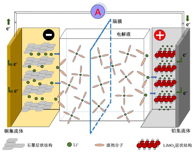
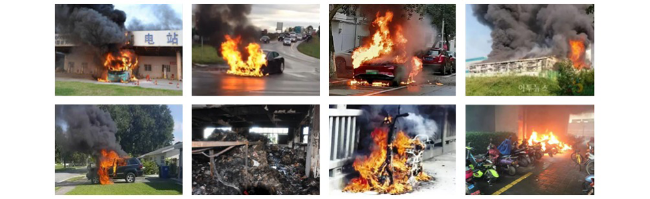
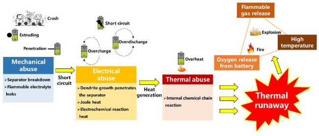
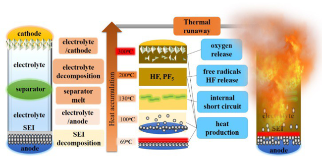
Lithium-ion batteries are widely used in mobile electronic products, electric vehicles, energy storage systems, aerospace and other fields due to their high energy and power density, long life and no memory effect. However, in recent years, the frequent safety accidents of electric vehicles and energy storage systems related to battery thermal runaway have attracted high attention. The high safety of high energy density batteries is the primary guarantee to promote the large-scale application of batteries, and the research on the characteristics of battery heat generation, thermal runaway mechanism, protection and suppression methods has become a hot topic in the field of battery thermal safety research in recent years. Therefore, the core issues in the field of battery thermal safety are comprehensively reviewed in this paper. Firstly, the thermal generation characteristics of the battery under normal conditions, the thermal runaway chain exothermic reaction and the failure mechanism of the battery under three kinds of abuse conditions are discussed; Secondly, the mechanistic equation, construction, application and evolution of the electrochemical-thermal coupling model and thermal runaway model are described; and then, the research progress of anode and cathode materials, separator, electrolyte and current collector safety modification technology are introduced; finally, this paper makes a prospect for the research trend in this field to provide ideas and directions for improving the intrinsic safety of lithium-ion batteries and preventing thermal runaway.

Cite this article

Shuyang Yu , Wenlei Luo , Jingying Xie , Ya Mao , Chao Xu . Review on Mechanism and Model of Heat Release and Safety Modification Technology of Lithium-Ion Batteries[J]. Progress in Chemistry, 2023 , 35(4) : 620 -642 . DOI: 10.7536/PC220935

Contents

1 Introduction
2 Lithium-ion battery and its safety problem overview
2.1 Operating principle
2.2 Battery safety accidents
2.3 Thermal runaway trigger factors
3 Heat release mechanism of lithium-ion batteries
3.1 Heat generation under normal operating conditions
3.2 Failure mechanism under thermal abuse
3.3 Failure mechanism under mechanical abuse
3.4 Failure mechanism under electrical abuse
4 Heat release models of lithium-ion battery
4.1 Electrochemical-thermal coupling model
4.2 Thermal runaway mechanism model
5 Safety modification technology
5.1 Modification of positive materials
5.2 Modification of negative materials
5.3 Modification of separator
5.4 Modification of electrolyte
5.5 Modification of current collector
6 Summary and Outlook

1 Introduction

For too long, we have relied on fossil fuels to power the electricity industry, heat our homes, and drive our cars. However, fossil fuel is a limited resource, and the fossil fuel that has been gradually formed in nature over millions of years may be completely exhausted by human beings in hundreds of years. Moreover, the use of fossil fuels is the main cause of many environmental problems (greenhouse effect, acid rain, etc.). Therefore, in 2012, the International Energy Agency emphasized the need to transform energy supply to cope with energy shortages and CO2-related climate change[1]. The efforts of modern society to get rid of the energy crisis and environmental pollution have been carried out for many years, and the challenges and hopes are intertwined. Today, advanced technologies can convert nuclear, wind, or solar energy into electricity with cleaner and more efficient processes. The coming era of electric energy promotes the energy source of energy storage system and transportation power system to change from fossil fuel to electric energy[2,3].
As a popular energy storage device, lithium-ion batteries are being widely used in portable electronic devices, electric vehicles, large-scale energy storage power stations and other power fields[4]. The growing anxiety of "endurance mileage" stimulates the rising energy density of traditional lithium-ion batteries, and high energy density is bound to be accompanied by high safety risks[5]. Therefore, there is an urgent need to improve the safety of lithium-ion batteries, so that they can have a longer application time and a wider range of applications.
In recent years, the research on battery thermal safety, which focuses on battery heat generation characteristics, thermal runaway mechanism, protection and control methods, has become a hot and important issue in the field of scientific research. Therefore, in order to reflect the development trend of this important field more comprehensively and timely, based on a large number of relevant literatures at home and abroad, this paper summarizes the internal heat release mechanism of lithium-ion batteries, the heat release model of single battery and the safety modification technology in recent years, and makes a prospect for the future research trend.

2 Overview of lithium-ion batteries and their safety issues

2.1 Principle of operation

Lithium-ion battery, also known as "rocking chair battery", is composed of four main components: positive electrode, negative electrode, electrolyte and separator. It mainly relies on the movement of lithium ions between the positive and negative electrodes to work. The working principle of a lithium-ion battery is shown in Figure 1.
图1 锂离子电池原理图

Fig.1 Schematic diagram of lithium-ion battery

When a lithium-ion battery is charged, lithium ions move from the positive electrode to the negative electrode, while electrons flow in through an external circuit. This process is reversed during discharge. The more lithium embedded in the electrode, the more total energy the battery can store and the longer it can last.
Positive side reaction:
L i M x O y L i 1 - x M x O y + x L i + + x e -
Negative side reaction:
n C + x L i + + x e - L i x C n
Total reaction of whole cell:
L i M x O y + n C L i 1 - x M x O y + L i x C n
The most popular commercial anode material is graphite. The positive electrode is mainly a layered oxide (such as lithium cobalt oxide), a polyanion (such as lithium iron phosphate), or a spinel (like lithium manganese oxide). The electrolyte is generally composed of an organic solvent and a lithium salt. The solvent is usually a mixture of organic carbonates such as ethylene carbonate (EC) or diethyl carbonate (DEC), etc., lithium salts such as lithium hexafluorophosphate (LiPF6), lithium hexafluoroarsenate (LiAsF6), lithium perchlorate (LiClO4) and lithium tetrafluoroborate (LiBF4), etc. The separator separates the positive and negative electrodes while allowing ions to pass through. The high oxidizability of the positive electrode, the high reducibility of the negative electrode and the low melting point and flammability of the electrolyte make the battery have potential safety hazards such as fire and explosion.

2.2 Battery safety accident

Some typical battery safety incidents are listed in Table 1. Fig. 2 is a picture of a partial battery fire accident. It can be seen that lithium-ion batteries can rupture, catch fire, or explode when exposed to high temperatures or short circuits. Lithium-ion batteries have a low probability of fire and explosion, but these widely reported incidents have worried consumers and forced millions of batteries to be recalled. Therefore, it is necessary to further study the thermal stability of each component of lithium-ion batteries and the heat release mechanism of single batteries, and further understand the nature of battery fire and explosion, so as to alleviate consumers'fear of battery safety and point out the direction for the design of the next generation of safer batteries.
表1 近年来的电池安全事故

Table 1 Battery safety accidents in recent years

时间 事故回放 事故原因
2020.04 深圳一家充电站内电动汽车起火,多辆电动汽车烧毁 过充导致热量积累,触发热失控链式反应
2020.10.27 一辆威马 EX5 在北京市中国科学研究院力学研究所内发生起火事故,后发生剧烈爆燃 电芯供应商在生产过程中混入了杂质,导致动力电池产生异常析锂,极端情况下可能导致电芯短路,引发动力电池热失控
2021.04.06 韩国忠清南道洪城光伏+储能系统起火爆炸,爆炸摧毁 0.5 MW储能电池 电池过流过压保护不足、运行环境及安装工艺有待改进,智能储能系统 ESS 经验不足
2021.04.16 北京市丰台区福威斯油气技术有限公司光储充一体化项目发生火灾爆炸事故,造成 1 人遇难,两名消防员牺牲。 磷酸铁锂电池单体发生内短路故障,引发电池模组热失控扩散起火
2021.07.18 浙江省杭州市父女骑电动车在玉皇山路行驶的过程中,电动车突然起火爆燃,车上父女被严重烧伤 初步判断“7·18”电动车起火原因与其锂电池故障有关
2021.07.30 位于澳大利亚维多利亚州的“维多利亚大电池”(VBB)项目所装载的特斯拉 Megapack 储能系统在施工建设期间发生起火事故 冷却液泄露导致锂电池热管理失控,在风力作用下引发相邻的另外一个储能系统燃烧
2021.09.04 加利福尼亚州 Vistra Energy 旗下莫斯兰丁锂离子储能站一期项目,7000 个电池组融化,占全部的 7% 热管理系统在极低的烟雾水平下错误启动,系统中部分柔性软管和管道上的少数接头发生故障引发系统喷水降温,造成电池损坏出现过热现象
2022.02.08 上海普陀区宜川四村住宅发生一起火灾造成 3 人死亡 住户将电动自行车锂离子蓄电池放在卧室内,电池故障引发火灾,引发火灾的锂电池输出电压超过 60 伏,属于典型的超标电池
图2 近年来部分电池安全事故

Fig.2 Some battery safety accidents in recent years

2.3 Thermal runaway trigger

According to the previous introduction of battery safety accidents, the safety problems of lithium-ion batteries mainly come from the thermal runaway of batteries[6]. As shown in Fig. 3, abuse conditions are the main source of thermal runaway triggering, such as mechanical abuse (needling, impact, extrusion, etc.), electrical abuse (overcharge, overdischarge, short circuit, etc.), thermal abuse (overheating). These three types of trigger forms have certain internal relations. Mechanical triggering leads to short circuit and electrical triggering, while electrical triggering releases heat and causes thermal triggering, which is the core of battery thermal runaway. Under the action of various internal and external factors, the harmful chemical exothermic reaction inside the battery starts. When the accumulated heat is greater than the heat dissipation, the internal temperature of the lithium-ion battery continues to rise, and eventually thermal runaway occurs.
图3 电池热失控触发因素

Fig.3 Trigger factors of battery thermal runaway

3 Heat release mechanism of single cell

3.1 Heat generation of battery under normal condition

To regulate the battery internal temperature, it is crucial to understand the heat generation and heat transport inside the battery. Even with a robust external thermal management system, the higher heat production inside the battery along with poor heat transport can still result in a noticeable temperature rise and large internal temperature gradient. Therefore, understanding the internal heat generation mechanism of the battery is the primary problem to solve the safe operation of the battery.
When the battery operates normally, the internal heat is generated by electrochemical reaction, phase change and mixing enthalpy, and the latter two are often ignored[7,8]. The total heat Q generated by a lithium-ion battery consists of two components, Qrev and Qirre. Qrev is the reversible heat of reaction due to the entropic heat and depends on the entropic heat coefficient, the temperature derivative of the equilibrium potential. The Qirre is irreversible heat, which is due to the overpotential heat produced by ohmic losses inside the cell, interfacial charge transfer and mass transfer losses. The calculation formula is shown in (4-6). Where V is the battery voltage, U is the equilibrium potential, I is the operating current, R is the internal resistance, and t is the operating time.
Q = Q r e v + Q i r r e
Q r e v = - I ( T U T ) t
Q i r r e = I U - V t = I 2 R t
The above formula is suitable for evaluating the heat generation of a small lithium-ion battery without the heat of mixing, the heat of phase change, the heat of side reaction, and neglecting the Joule heat of the current collector. For the heat generation of large batteries used in pure electric vehicles, Kim et al. Considered that in addition to the heat generation of electrochemical processes (reversible reaction heat and irreversible impedance heat), the Joule heat generated by current collectors should also be included[9,10]. Kim et al. Used a two-dimensional model to couple the Joule heat generated by the current collector into the electrochemical model in the form of an electrical model according to Ohm's law, and the heat generation equation obtained is as follows:
q = a J [ ( V - U ) + T U T ] + a p R p i p 2 + a n R n i n 2
Where A is the specific surface area of the cell (m-2),J is the current density (A·m-2),U is the open circuit voltage (V),V is the working voltage of the cell (V),ap and an are the specific surface (m-2),ip and in of the positive and negative electrodesAre the linear current densities of the positive and negative electrodes (A·m-2),Rp and Rn are the resistances of the positive and negative electrodes (Ω), respectively. The first term on the right side of the equation is the heat due to charge transfer at the electrode/electrolyte interface, including an irreversible part representing the energy loss due to the deviation of the cell potential from the open circuit potential caused by electrochemical polarization, and a reversible part representing the heat due to entropy change; The latter two terms come from the Joule heating of the positive and negative electrodes, respectively. Reasonable design of the position and size of the tab can minimize the values of the latter two items.
Determining the heat generation rate of lithium-ion battery is of great significance for the design of battery thermal management system and the prediction of transient temperature rise during dynamic operation. Mao et al. Studied the heat generation characteristics of LiCoO2/C battery under different conditions, and measured the reversible and irreversible heat generation by calorimetric method and electrochemical method respectively, both of which were consistent, but the former was more feasible[11]. It is determined by analysis that the reversible heat generation is related to the electrode material and battery capacity, while the irreversible heat generation is related to the resistance and current. Taking the commercial cylindrical 18650 lithium-ion battery with NCM ternary cathode material as an example, Liu et al calculated the heat generation rate of the battery by full matrix orthogonal experimental design method[12]. Based on the consideration of depth of discharge (DOD), discharge rate and ambient temperature, 176 overpotential tests and 66 entropy coefficient tests were carried out, and it was found that the average heat generation rate was approximately quadratically nonlinear dependent on the discharge rate. In addition, the third-order transient heat generation rate model of lithium-ion battery was established by response surface methodology (RSM) and correlated with each influencing parameter.

3.2 Failure mechanism of battery under thermal abuse

When the battery is exposed to abusive conditions, the temperature may exceed the normal operating range, and the active materials can decompose or react with each other, eventually leading to thermal runaway. The electrochemical reaction process in lithium-ion batteries at high temperature is very complex. Taking a lithium-ion battery with a positive electrode made of lithium cobalt oxide as an example, the thermal runaway process can be summarized as shown in Figure 4[13]. As shown in Fig. 4, with the increase of temperature, exothermic side reactions such as decomposition of SEI film, reaction between anode material and electrolyte, reaction between cathode material and electrolyte, decomposition of electrolyte, and reaction between anode and binder occurred in the battery. Many of these occur in parallel.
图4 锂离子电池热失控链式反应示意图[13]

Fig.4 Schematic diagram of thermal runaway chain reaction of lithium-ion battery[13]

Feng et al. Conducted adiabatic thermal runaway tests on a large number of battery samples, disassembled the battery, and conducted differential scanning calorimetry (DSC) tests on the combination of battery components[14]. The test results were jointly analyzed to analyze the common thermal runaway behavior of the battery. The thermal runaway process is divided into three stages according to the breakdown of the separator and the redox reaction between the positive electrode and the negative electrode (Fig. 5). In the first stage, the diaphragm is intact, and the "negative electrode + electrolyte" system and the "positive electrode + electrolyte" system react separately. The heat generated by the "positive electrode + electrolyte" system at this stage is low and can be ignored, and the heat generated by the "negative electrode + electrolyte" system accounts for about 17% of the total heat of the thermal runaway process. In the second stage, the diaphragm collapses, and a part of the solvent still exists in the electrolyte (the boiling point of EC is 248 ℃), while the other part evaporates. Internal short circuit occurs, which releases the electric energy stored in the battery, but the heat released by internal short circuit only accounts for 9% of the total heat. The third stage: the redox reaction between the positive electrode and the negative electrode starts and releases a large amount of heat, accounting for 74% of the total heat. It should be noted that the accelerating rate calorimeter (ARC) can detect the heat release behavior of battery thermal runaway under adiabatic conditions and provide temperature and pressure data, but it lacks the heat production of battery thermal runaway product gas and battery material combustion, so the three-stage division does not include the heat production of combustion.
图5 热失控的“三阶段”[14]

Fig.5 “Three stages” of thermal runaway[14]

3.2.1 Study on Thermal Stability of Battery Materials

As the temperature of lithium-ion battery increases, it will gradually trigger the exothermic side reaction of the internal materials of the battery, which will cause irreversible damage to the battery and eventually lead to thermal runaway. However, the internal side reactions are superimposed on each other, which makes it difficult to quantify accurately. Therefore, from the material level, it is necessary to clarify the initial temperature, maximum temperature, final temperature and thermal temperature of the exothermic reaction of each component of the target battery, so as to sort out the chain reaction process of thermal runaway of lithium-ion batteries and determine the trigger mechanism of thermal runaway.
(1) Thermal stability of SEI film
Solid electrolyte interface (SEI) is a thin layer formed on the graphite anode, which is the result of irreversible electrochemical decomposition of the electrolyte. At room temperature, the SEI film can prevent oxidation, reduce chemical reaction, and reduce self-discharge and capacity fading. However, the SEI film grows with increasing temperature and becomes critical for a long time. The SEI film consists of two parts: the stable components (such as LiF and Li2CO3) and the metastable components (such as ROCO2Li and (CH2OCO2Li)2)), which can protect the negative electrode from further reaction with the electrolyte[15]. Although many studies have been conducted on the thermal decomposition behavior of SEI films from different perspectives, no general consensus has been reached. It is generally believed that at 80 ~ 120 ℃, the metastable layer of the SEI film begins to decompose and generate a small amount of heat. This decomposition reaction is also the beginning of the thermal runaway "self-heating" of the lithium-ion battery. The reaction formula is as follows:[16,17]
( C H 2 O C O 2 L i ) 2 L i 2 C O 3 + C 2 H 2 + C O 2 + 0.5 O 2
(2) Thermal stability of negative electrode + electrolyte
SEI film can be decomposed at lower temperature. In addition, Li intercalated into graphite can also react with the metastable component (CH2OCO2Li)2 to form the stable components Li2CO3 and C2H4. The decomposition of the SEI film not only heats up the battery, but when the SEI film cannot protect the negative electrode, the electrolyte solvent reacts with the lithium-intercalated carbon negative electrode as follows:
2 L i + C 3 H 4 O 3 E C L i 2 C O 3 + C 2 H 4
2 L i + C 4 H 6 O 3 ( P C ) L i 2 C O 3 + C 3 H 6
2 L i + C 3 H 6 O 3 ( D M C ) L i 2 C O 3 + C 2 H 6
The reaction of lithium intercalation carbon anode with electrolyte releases a large amount of heat and spans a wide temperature range, which may occur at 100 ~ 250 ℃, and the reaction exothermic rate and gas production rate reach the peak near 220 ℃.The structure of the negative electrode collapses, releasing a large amount of heat and gas, and the generated gas quickly builds up a high pressure inside the battery, while forming a thick non-conductive layer of lithium salt on the surface of the negative electrode, which is mainly composed of LiF and Li2O[18].
(3) Thermal stability of diaphragm
As a physical barrier, the separator can isolate the direct contact between the positive and negative electrodes and accommodate the electrolyte to promote the transport of ions inside the battery. The importance of the separator is self-evident, and the failure of the separator will bring serious risks to the battery[19]. Polyethylene (PE) and polypropylene (PP) separators have melting temperatures of 135 and 166 ° C, respectively, while some ceramic separators can maintain structural integrity after 200 ° C. However, with the further increase of temperature, the diaphragm shrinks further, and the positive and negative electrodes will contact each other, resulting in internal short circuit and a large amount of Joule heat[20]. Internal short circuit is an important cause of thermal runaway, and the electric energy released by internal short circuit during thermal runaway is approximately equal to the electric energy stored in the battery[21].
(4) Thermal stability of positive electrode + electrolyte
The decomposition temperature range of the cathode material is 150 to 250 deg C. When the temperature rises to the decomposition temperature, the cathode material decomposes to release oxygen. The decomposition temperature depends on the composition of the positive electrode and the state of lithium intercalation. The thermal stability of the positive electrode roughly follows: lithium iron phosphate (LiFePO4,LFP)> lithium manganese oxide (LiMn2O4)> ternary (LiNixCoyMnzO2,NCM)> ternary (LiNixCoyAlzO2,NCA)> lithium cobalt oxide (LiCoO2,LCO).
LCO is the earliest cathode material for lithium-ion batteries, which has poor thermal stability. The decomposition path of LCO at high temperature is as follows:[22]
3 L i x C o O 2 3 x L i C o O 2 + ( 1 - x ) C o 3 O 4 + ( 1 - x ) O 2
C o 3 O 4 3 C o O + 0.5 O 2
C o O C o + 0.5 O 2
Biensan et al. Determined that the heat release of the reaction between Li0.45CoO2 and electrolyte (1 M LiPF6/PC∶EC∶DMC=1∶1∶1) at high temperature was 450 J·g-1, the reaction temperature ranged from 220 to 500 ° C, and the oxygen release temperature was 230 ° C[23].
The decomposition of NCA can be expressed as:[24]
L i x ( N i 0.8 C o 0.15 A l 0.05 ) O 2 ( R 3 ¯ m ) 1 + x 3 [ L i 3 x 1 + x ( N i 0.8 C o 0.15 A l 0.05 ) 3 x 1 + x O 4 ] ( F d 3 ¯ m ) + 1 - 2 x 3 O 2
L i x ( N i 0.8 C o 0.15 A l 0.05 ) O 4 ( 1 + x ) 3 ( F d 3 ¯ m ) L i x ( N i 0.8 C o 0.15 A l 0.05 ) O 1 + x ( F m 3 ¯ m ) + 1 + x 6 O 2
The heat generation of NCA in 1 M LiPF6(EC:DEC)[25]. Huang et al. Used differential scanning calorimetry (DSC), thermogravimetric analysis and mass spectrometry (TGA-MS) to find that the mixture of Li0.1(Ni0.8Co0.15Al0.05)O2 and electrolyte began to release heat at about 200 ℃, and the total heat production was 793 J·g-1[26].
Due to the high price of cobalt in traditional NCM materials, relevant practitioners reduce the use of cobalt by increasing the content of nickel, thus reducing the cost of batteries, and the increase of nickel content also helps to improve the energy density of batteries. Therefore, NCM materials have evolved from the original NCM111 to NCM424, NCM523, NCM622, and even NCM811. In the NCM cathode, the role of Co is to stabilize the layered structure of the material and improve the cycle and multiplication performance of the material; The function of Mn is to reduce the cost of materials and improve the safety and structural stability of materials. In addition, the effect of Ni is to increase the energy density of the material[27]. However, the greater energy density brought by Ni means that the positive electrode structure is less stable with respect to thermal issues[28]. During the thermal runaway process, the trigger temperature decreases with the increase of Ni content, while the total heat production also increases. Therefore, the effect of Ni content on thermal runaway is significant, and the effect of Co and Mn on thermal runaway is small.
The NCM first transforms from a layered structure (space group R 3 - m) to a disordered LiM2O4-type spinel and M3O4-type spinel phase (space group F d 3 - m). At higher temperatures (600 ° C), these two disordered spinel phases coexist in the absence of electrolyte[29]. The electrolyte can accelerate the thermal decomposition of the cathode material, and when heated to 600 ℃, the spinel transforms into MO-type rock salt phase ( F m 3 - m) and metal phase[30]. Roder proposed the decomposition reaction of NCM:[31]
N C M ( R 3 - m ) ( M n , N i ) O ( F m 3 ¯ m ) + C o O + N i + O 2
During the delithiation (charging) process of the cathode, Ni2+, Co3+ are oxidized into Ni3+, Ni4+, and Co4+. The unstable Ni4+ in NCM is the most important factor leading to the reduction of the thermal stability of the positive electrode. During the heat-driven reduction of Ni4+ to Ni2+, the positive electrode releases oxygen, which reacts with the electrolyte and the negative electrode to produce a large amount of heat. The possible reactions between the oxygen evolution of the positive electrode and the electrolyte are as follows:[32]
C 3 H 4 O 3 ( E C ) + 2.5 O 2 3 C O 2 + 2 H 2 O
C 4 H 6 O 3 ( P C ) + 4 O 2 4 C O 2 + 3 H 2 O
C 3 H 6 O 3 ( D M C ) + 3 O 2 3 C O 2 + 3 H 2 O
C 2 H 5 O C O O C 2 H 5 ( D E C ) + 6 O 2 5 O 2 + 5 H 2 O
C 4 H 8 O 3 ( E M C ) + 4.5 O 2 4 C O 2 + 4 H 2 O
The decomposition of LMO can be represented by the following reaction:[6]
M n 2 O 4 M n 2 O 3 + 0.5 O 2
L i 0.2 M n 2 O 4 0.2 L i M n 2 O 4 + 0.8 M n 2 O 4
3 M n 2 O 4 2 M n 3 O 4 + 2 O 2
L i M n 2 O 4 L i M n O 2 + 1 / 3 L i M n O 2
L i M n 2 O 4 L i M n O 2 + 1 / 3 M n 3 O 4 + 1 / 3 O 2
Zhang et al. Reported that the heat production of LixMn2O4 after adding electrolyte was 350 J·g-1, and the temperature range was 225 – 400 ° C[33]. Early Biensan et al. Reported that its heat production was 450 J·g-1, and the temperature range was 150 – 300 ° C[23]. Wang et al. Measured the heat generation and thermodynamic data of LixMn2O4 and its mixture with electrolyte[34]. Measurements of the mixture of LixMn2O4 and 1 M LiPF6/EC+DEC electrolyte at 4.3 V exhibited three exothermic peaks with a total calorific value of 2014.3 J·g-1 and an onset temperature of 89 ° C.
LFP material has become one of the most common cathode materials because of its low cost, excellent safety, long service life and other advantages, and is widely used in energy storage systems or power vehicles. But the lower voltage plateau (~ 3.5 V) of LFP materials limits its energy density, and related practitioners solve this defect (~ 4.1 V) by doping Mn[35]. The improved safety of LFP is attributed to the stronger P — O covalent bond of the (PO4)3- polyanion[36,37]. Some researchers believe that LiFePO4 do not release oxygen at high temperatures[38,39]. However, it has also been suggested that FePO4 may also decompose[40].
2 L i 0 F e P O 4 F e 2 P 2 O 7 + 0.5 O 2
(5) Thermal stability of electrolyte.
The decomposition reaction of electrolyte is complex, involving a variety of chain reactions. The thermal decomposition of lithium salt LiPF6 at high temperature (after 206 ℃) will produce strong Lewis acid PF5, which will react with water in the solvent to produce hydrofluoric acid HF.
L i P F 6 L i F + P F 5
P F 5 + H 2 O P F 3 O + 2 H F
If there is a small amount of water inside the cell, the LiPF6 hydrolysis reaction begins to occur at temperatures near 30 ° C or even lower.
L i P F 6 + H 2 O L i F + P F 3 O + 2 H F
The pyrolysis and hydrolysis reactions of LiPF6 produce a large amount of HF gas. HF is not only a highly toxic gas, but also has a great destructive effect on the SEI film, resulting in the rapid decomposition of the SEI film. The initial thermal decomposition temperature of the electrolyte lags behind the reaction of the mixture of the negative electrode with the electrolyte and the positive electrode with the electrolyte, and a large part of the electrolyte has been consumed by the positive and negative electrodes before the thermal decomposition of the electrolyte begins, and in the temperature range of 180 ~ 200 ℃, the battery has generally been gassed, so the contribution of the thermal decomposition reaction of the electrolytic solution to the thermal runaway of the whole battery is small.
To sum up, a typical thermal abuse process of lithium-ion battery can be summarized as the following stages: decomposition and reconstruction of negative electrode SEI film, reaction of negative electrode lithium intercalation with electrolyte solvent, internal short circuit caused by separator melting, reaction of positive electrode decomposition oxygen with electrolyte solvent and negative electrode, electrolyte decomposition, etc. As these reactions occur and gas decomposition products accumulate, the temperature and pressure inside the lithium-ion battery rise. Once the critical point is reached, the released gas can easily catch fire at high temperatures, further increasing the risk of thermal runaway. Many of the above reactions overlap in the temperature range, and even some reactions do not necessarily occur, depending on the physical parameters of the battery (such as different electrode materials, different battery designs, etc.), the working parameters of the battery, and the triggering conditions.

3.2.2 Study on the Safety of Battery Cell

The root cause of battery thermal runaway is a series of irreversible exothermic side reactions caused by heat accumulation/temperature rise, which occur one after another, releasing a large amount of heat and forming a chain reaction. At present, the thermal runaway characteristics of lithium-ion power battery are mainly studied from the aspects of battery voltage, temperature and heat release rate, in order to provide support for the design of thermal runaway warning and safety management system.
Based on a large number of adiabatic thermal runaway experimental test data of batteries with different systems and shapes, Feng Xuning et al. Of Tsinghua University summarized and defined three characteristic temperatures (T1, T2, T3) in the thermal runaway process to quantitatively evaluate the thermal runaway characteristics of batteries[41]. The T1 is the measurable onset temperature of heat generation, and the mechanism of this heat source is usually attributed to SEI film decomposition. T2 is the trigger temperature for thermal runaway, and defining T2 is important for the safe design of batteries, where higher T2 means better overall thermal stability, and batteries are more likely to pass standard abuse tests. However, there is no quantifiable definition of T2. The value of dt/DT can be used as a measurement standard, and the 1℃·s-1 is generally used as a criterion for T2. The T3 is the maximum temperature that the battery can reach during thermal runaway[42]. The temperature response and temperature rise rate response trend of the battery cell during the adiabatic thermal runaway test are shown in Figure 6.
图6 电池热失控的特征温度

Fig.6 Characteristic temperature of battery thermal runaway

Based on this, the members of the group have carried out a large number of studies[43~45]. For a long time, internal short circuit has been considered as the trigger of thermal runaway. However, Liu et al. Found that not only internal short circuit, but also the chemical cross-reaction between positive and negative electrodes is the mechanism behind thermal runaway[46]. In situ experiments show that during thermal runaway, the positive electrode phase transition releases oxygen, which is consumed by the lithiated negative electrode. The released highly oxidizing gas reacts with the reducing LiCx to generate a large amount of heat at 274.2 ° C, and the heat flow is 87.8 W·g-1. In order to confirm the proposed mechanism, a single crystal NCM523/Gr cell in the process of thermal runaway was frozen with liquid nitrogen and analyzed in detail. The results reveal the hidden mechanism of thermal runaway, which is caused by the chemical cross reaction between the positive and negative electrodes, and can occur before the internal short circuit, as shown in Figure 7. These findings provide important insights into the rational design of lithium-ion and solid-state batteries.
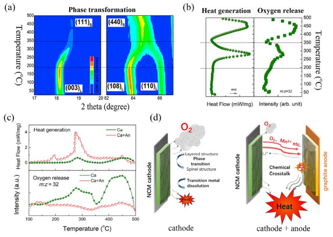
图7 正负极交叉化学反应触发热失控[46]。(a) 带电正极材料的时间分辨 XRD 谱图;(b) 带电正极材料在不同温度下的原位产热和释氧;(c) 在 100~500℃ 内,正负极的混合物几乎不释放氧气,但有明显的产热增强;(d) 正负极交叉化学反应过程

Fig.7 Thermal runaway triggered by chemical crosstalk between the cathode and anode[47]: (a) time-resolved XRD patterns of charged cathode material; (b) in situ heat generation and oxygen release at different temperatures of charged cathode materials; (c) at 100~500℃, the mixture of cathode and anode releases virtually no oxygen but has sharp heat generation enhancement; (d) cathode and anode cross chemical reaction process

Considering the balance of Ni, Co and Mn elements, NCM523 material is considered to be the best composition with good thermal stability while maintaining high capacity[47]. The NCM523-based battery shows a watershed in battery safety. In this sense, the thermal runaway of NCM811-based batteries is more severe. Li et al. Conducted DSC tests on NCM811/Gr (graphite) battery modules, decoupled the battery module combinations that caused thermal runaway, and determined that the reaction between the positive electrode of NCM811 and the electrolyte triggered thermal runaway[48]. Transmission electron microscopy characterization by simultaneous X-ray diffraction and in situ heating showed that the violent exothermic reaction was caused by released oxygen atoms. The rapid reaction of highly active oxygen with the electrolyte is accompanied by a large amount of heat release, which accelerates the phase change of the charged positive electrode. The mechanism was verified by confirmatory experiments, and the phase transition of the charged positive electrode could be inhibited when the highly reactive oxygen species was captured by the anion receptor.
In order to break the reaction chain of thermal runaway, it is very important to determine the reaction pathway of oxygen. Hou et al. Demonstrated that two endogenous oxygen pathways were involved in the strong exothermic reaction, resulting in the uncontrollable state of the NMC811/Gr soft-pack battery[49]. This study quantifies the individual contribution of these oxygens to thermal runaway. About 41% of the active oxygen reacts violently with ethylene carbonate (EC) at the cathode/electrolyte interface, generating 16% of the heat, accelerating the self-generated heat rate and triggering thermal runaway, as shown in Figure 8.
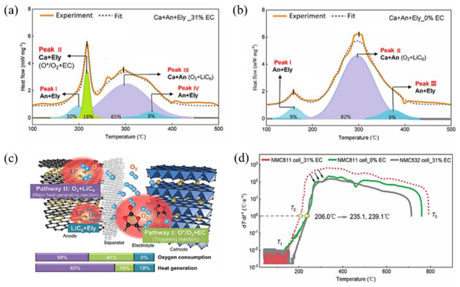
图8 两种内源性氧途径参与热失控强放热反应[49]。(a) 样品 Ca+An+Ely_31%EC 的 DSC 曲线分峰拟合;(b) 样品 Ca+An+Ely_0%EC 的 DSC 曲线分峰拟合;(c) 正极释氧的机理和途径;(d) 无 EC 电解液的 NMC811/Gr 电池(0%EC)与对照组(31%EC)的热失控温升速率比较

Fig.8 Two endogenous pathways of oxygen involved in thermal runaway strong exothermic reactions[50]: (a) peak fitting of DSC curve of Ca+An+Ely_31%EC sample; (b) peak fitting of DSC curve of Ca+An+Ely_0%EC sample; (c) mechanism and pathway of oxygen release from cathode; (d) thermal runaway temperature rise rate of NMC811/Gr battery with EC-free-electrolyte (0%EC) compared with the control set (31%EC)
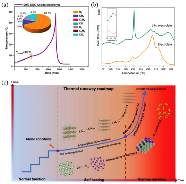
O 2 ( 2 O * ) + 0.4 C 3 H 4 O 3 ( E C ) 1.2 C O 2 + 0.8 H 2 O
The oxygen remaining after the reaction with carbonate diffuses to the lithiated negative electrode, generating 65% of the heat, allowing the battery to reach the maximum damage temperature during thermal runaway.
O 2 + 4 L i C 6 2 L i 2 O + 4 C 6
Subsequently, Wu et al. Reported an EC-free ternary electrolyte for high-safety, high-specific energy NMC811/Gr soft-pack batteries[50]. This EC-free electrolyte can effectively stabilize the NMC811 surface at high potentials (up to 4.5 V), creating a stable interface to achieve good compatibility with the graphite negative electrode. This electrolyte strategy significantly improves the intrinsic safety (thermal runaway trigger temperature increased by 67.0 ° C), excellent electrochemical performance (4.2 V, Coulombic efficiency approximately equal to 100% after 200 cycles), and superior high voltage stability (4.5 V, capacity retention of 82.1% after 200 cycles).
Thermal runaway is always a thermoelectric coupling process in which exothermic chemical reactions and internal short circuits coincide and interact with each other. The trigger mechanism of T2 is quite complex, which is caused by several key reactions, including a large number of internal short circuits and reactions between oxygen released from cathode materials and organic solvents or lithiated graphite. Ren et al. Designed a liquid nitrogen thermal runaway test and post-mortem analysis to characterize the cause of internal short circuit, and found that the thermal shrinkage of the diaphragm was the main cause of internal short circuit.However, the Joule heat generated by the internal short circuit is limited by the sharp increase of the battery resistance, which does not contribute much to the thermal runaway of the battery. However, the exothermic reaction between the graphite anode and the electrolyte can directly trigger the thermal runaway of the NCM333/Gr battery[51]. Subsequently, Zheng et al. Deeply studied the reaction mechanism of lithiated graphite and electrolyte at high temperature, and tested the combination of lithiated graphite and different electrolyte components (diethylene carbonate DEC, ethyl methyl carbonate EMC, ethylene carbonate EC and LiPF6) by DSC.To determine the role of each component in the electrolyte in the exothermic reaction, EC and LiPF6 were found to be the key components for the reaction with lithiated graphite, while DEC and EMC contributed little to the total heat production[52]; The equation of exothermic reaction was summarized by on-line detection of gas formation during heating. The quantitative relationship between lithiated graphite and electrolyte in the exothermic reaction was clarified by DSC test of lithiated graphite and electrolyte samples with different mass ratios, and 2. 5 mg of lithiated graphite Li0.8627C6 can fully react with 7. 2 mg of electrolyte to release 2491 J·g-1 of heat.
Lithium-ion battery fire can be generally divided into three stages of evolution: battery failure under various incentives, thermal runaway, gas leakage and fire combustion. A large amount of heat is generated in the thermal runaway induction stage, the combustible gas is ejected from the inside of the battery case and mixed with the surrounding air to heat the battery surface during the blow-down process, and the ejected high-energy particles can act as an ignition source. Therefore, the thermal runaway fire of lithium-ion battery itself has three elements of ignition. From the perspective of fire safety, it is of great significance to observe lithium-ion batteries, deeply understand the thermal runaway evolution process, gas leakage and eruption characteristics, and the combustion characteristics of single and module lithium-ion batteries, which is of great guiding significance for the formulation of fire prevention and control and fire extinguishing strategies of lithium-ion batteries.
Wang Qingsong's research group at the University of Science and Technology of China has also carried out a lot of research on single thermal runaway behavior, thermal runaway propagation between modules and fire prevention and control technology. For a single cell, Zhong et al. Conducted a series of combustion tests on 18650 lithium-ion batteries using a modified cone calorimeter[53]. The temperature, voltage change, heat release rate and gas production of the cell during the combustion process were measured, and it was proposed that the thermal runaway warning system should consist of three parts: voltage warning, temperature measurement and gas detection. Mao et al. Used ARC to test 18650 NCM523/Gr batteries with different charge States (0%, 50%, 75%, 100% SOC)[54]. A comprehensive study of autothermal reaction and thermal runaway criticality was carried out. The influence of SOC on the critical state of thermal runaway is analyzed, and it is concluded that with the decrease of SOC, the self-heating reaction and thermal runaway are delayed in temperature and time. Huang et al. studied the key characteristics and transition process of thermal runaway of lithium-ion battery through experimental test and model prediction, defined the environmental state of battery: safe zone, critical zone and dangerous zone, and analyzed the transition process of thermal runaway by means of XRD and SEM[55]. The results show that the lattice constant of ternary NCM materials decreases gradually with the increase of temperature, and finally transfers to nickel, cobalt and manganese oxides, while the lithium embedded in the negative electrode is gradually consumed by the reaction with the electrolyte and binder in the transition process.
With the use of new electrolytes, the mechanism of thermal runaway has been constantly updated. Huang et al., Qingdao Bioenergy and Process Research Institute, studied 5 Ah NCM523/Gr soft-pack battery based on LiTFSI-LiDFOB two-salt electrolyte, and innovatively proposed through various advanced characterization technologies.The LiH-induced exothermic reaction at the negative electrode side and the migration of H2 to the positive electrode side are the root triggering factors for the thermal runaway of NCM523/Gr soft pack battery, while the phase change of lithiated graphite and oxygen release from NCM523 are the accelerating factors for the thermal runaway, as shown in Fig. 9[56].
图9 LiH诱导的负极侧放热反应以及H2向正极侧迁移触发热失控[56]

(a) 100%SOC 负极/电解液混合体系的 ARC 实验及产气组成;(b) 双盐电解液及LiH/双盐电解液在 N2 气氛下的DSC曲线;(c) 满电态 NCM523/Gr 电池热失控路径图

Fig.9 Thermal runaway is triggered by LiH-induced exothermic reaction at anode side and H2 migration to cathode side[57].

(a) ARC temperature rise curve and gas generation composition of 100%SOC anode/electrolyte; (b) DSC curves of dual electrolyte and LiH/dual electrolyte under N2 atmosphere; (c) thermal runaway route map for fully charged NCM523/Gr battery

In the exothermic reaction inside the battery, the negative electrode/electrolyte contributes to the initial heat accumulation in the thermal runaway process, and the replacement of volatile and flammable liquid electrolytes (LEs) used in traditional lithium-ion batteries with non-flammable solid electrolytes (SEs) can improve battery safety.Therefore, all-solid-state batteries (ASSBs) are generally considered to be safe batteries compatible with lithium metal negative electrodes[57,58]. Chen et al. Of the Institute of Physics of the Chinese Academy of Sciences studied the thermal stability of four common inorganic oxide solid electrolytes (SEs) and metal lithium through ARC test, compared the initial temperature and heat generation rate of different material systems, and determined that the thermal stability of the four solid electrolytes changed in the order of Li: LAGP < LATP < LLTO < LLZO[59]; First-principles calculations and thermodynamic analysis show that the highly exothermic reaction between oxygen released from SEs and molten metal Li triggers a heat runaway. Finally, the multi-step reaction mechanism of thermal runaway of all-solid-state battery using Ti/Ge-based SEs is proposed, as shown in Fig. 10, the high temperature and close interfacial contact after lithium melting will accelerate the interfacial reaction, and the heat generated by it will further promote the thermal decomposition of SEs and the generation of O2, and a large amount of heat generated by the reaction between Li and O2 will finally trigger thermal runaway. Yan et al. Of Yanshan University used multi-scale methods such as in-situ optical microscopy and cryogenic transmission electron microscopy, combined with density functional theory, to reveal the failure mechanism of Li1.3Al0.3Ti1.7P3O12(LATP)[60]. It is different from the mechanism that Li reacts with O2 released from LATP during heating to form Li2O to produce a large amount of heat to trigger thermal runaway. It is found that the LATP+Li→Li3PO4+LiP+Li0.5TiO2 reaction at high temperature releases heat of 51.41 kJ·mol-1, which leads to the further formation of Li3P and Li2O, while the microcracks caused by the volume expansion of LATP accelerate the diffusion of molten Li into LATP and also intensify the exothermic reaction between them. The instability of co-top PO4 tetrahedra and TiO6 octahedra against Li at high temperature is the fundamental cause of LATP thermal runaway triggering. The diffusion of Li+ into LATP leads to the collapse of PO4 tetrahedra and TiO6 octahedra to form Li-O, Li-P-O, and Li-Ti-O species, which release a large amount of heat and trigger LATP thermal runaway.
图10 无机氧化物固态电解质与金属锂的多步热失控反应路径图[59]

Fig.10 Multi-step thermal runaway route map for SEs and metallic Li[60]

3.3 Failure mechanism of battery under mechanical abuse

The contributions of Internal short circuit (ISC) and exothermic chemical reactions in the thermal runaway process are difficult to separate. Under the condition of mechanical abuse, the occurrence of ISC will release a large amount of Joule heat, which can directly trigger the runaway of heat. The mechanical abuse (needling, indentation, etc.) of ISC mainly refers to the invasion of foreign bodies or mechanical deformation of the battery under the action of external forces, resulting in the formation of electrical connection between the positive and negative materials.
Puncture test to simulate internal short circuit is a commonly used method to evaluate the safety performance of batteries. Wang et al. Of the University of Science and Technology of China studied the internal short circuit phenomenon of lithium-ion batteries caused by penetration through needling experiments, numerical simulation and thermal analysis of battery diaphragms.Needling was found to determine the short-circuit current as well as the battery heat dissipation, and in the case of thermal runaway, the larger diameter nail provided a larger short-circuit current, resulting in a larger total heat production rate and a shorter time required to trigger thermal runaway[61]. In the case of non-thermal runaway, the larger the nail diameter, the larger the shortening area, and the stronger the heat dissipation capacity. The cell voltage after insertion decays exponentially with time, and the fluctuation and rebound of the voltage during insertion are attributed to the partial interruption of the internal short circuit path. Xu et al. Studied the thermal runaway mechanism of lithium-ion soft-pack batteries through a series of needling experiments, and selected four parameters, including state of charge, needling speed, needling position and nail diameter, to study their effects on thermal runaway[62]. The results show that the higher the organic carbon content of the negative electrode, the easier the thermal runaway of the battery during the needling process, and the higher the peak temperature. The needle position determines the battery short circuit position; The needle speed has little effect on the thermal runaway of the battery. The larger the nail diameter, the more serious the cell damage, and the larger the initial heating rate and peak temperature. In order to carry out detailed field diagnosis, Huang et al. Of the University of Alabama in the United States proposed a small, slow, in-situ sensing pinprick test method, which can be applied to 3 Ah soft-pack batteries to separate the process of ISC and thermal runaway.The details of ISC can be provided at the level of individual pole piece and current collector. Multiple in-situ temperature peaks are observed within 100 s before thermal runaway. These initial peaks exceed the safety limit, but the temperature drops rapidly after each peak without causing thermal runaway immediately[63]. Further study shows that the initial temperature peak occurs when the spike tip reaches the aluminum current collector, forming a low-resistance ISC between the negative electrode and the aluminum current collector. The rapid drop in temperature after each peak is attributed to the sudden drop in ISC current, which is mainly due to the cracking of the aluminum foil and the increase in contact resistance.
Because metal pins conduct both heat and electricity, needling is not an effective way to study material response and failure mechanisms. Zhu et al., Oak Ridge National Laboratory, USA, conducted mechanical indentation tests on commercial lithium-ion batteries with different capacities and SOCs, and systematically studied the external characteristics and internal structural changes of batteries when ISC occurred by in-situ and ex-situ methods. X-ray computed tomography (XCT) results showed that.ISC is the combined result of shear banding or other strain localization modes in the electrode assembly, shear offset in the electrode particle coating, and concomitant ductile fracture in the current collector,It is proposed that the irregular strain localization pattern, the mismatch of the mechanical properties of different layers, and the geometric characteristics of the indenter eventually lead to the tearing/puncturing of the battery separator at different locations[64]. Lee et al. Of Konkuk University, Korea, proposed a mechanical-electrochemical-thermal two-way nonlinear coupling analysis method to analyze the internal short circuit caused by quasi-static indentation and predict the voltage drop and temperature rise[65]. This method uses the material nonlinearity of battery components to calculate the internal short circuit caused by mechanical deformation and positive and negative electrode contact, taking into account the detail layer. The heat generated by the internal short circuit is calculated by the electrochemical model composed of Randles circuits. The heat source in the electrochemical model is coupled to the thermal model to calculate the temperature variation with time. The voltage drop and temperature rise predicted by the model are in good agreement with the experimental results of 3. 2 Ah soft-pack battery with three different diameters.

3.4 Failure mechanism of battery under electric abuse

Overcharge and overdischarge are the most common battery system failures, which seriously affect the safety and service life of lithium-ion batteries. Generally, charging system failure, unreasonable design of battery management system (BMS), inconsistency of single unit in battery system and loose connection will lead to electrical abuse of battery system.
Overcharge refers to the excessive continuous charging of the battery above the operating voltage or by applying a voltage higher than the specified charging voltage, which is one of the most common faults of the battery system. If there is no appropriate response, it may lead to catastrophic consequences such as fire and explosion. When the voltage continues to rise, the NCM cathode material will be destroyed and decomposed under high voltage conditions (> 4.5 V). As the voltage continues to rise (4.9 ~ 5 V), the traditional electrolyte (1 M LiPF6/EC∶DEC∶DMC=1∶1∶1) will be oxidized to produce alkanes such as CH4; Due to the limited capacity of the graphite negative electrode, too many lithium ions can not be fully embedded in the negative electrode, and the lithium evolution reaction begins. At the same time, excessive lithium removal will also lead to the structural collapse of the positive electrode, resulting in a slight drop in voltage and an increase in the internal resistance of the battery. As the overcharge continues, the accumulation of Joule heat is more serious. When the temperature is higher than 60 ℃, the excessive temperature will aggravate various side reactions inside the battery (such as electrolyte oxidation, reaction between delithiated positive electrode and electrolyte, reaction between electrolyte and lithium, etc.), and produce various gases (CO, CO2, O2, H2, and C2H4, etc.); The exothermic side reaction will further aggravate the temperature rise of the battery, leading to the decomposition of the SEI film. With the continuous accumulation of heat, when the battery temperature reaches the melting temperature of the separator, a large area of internal short circuit will occur, which will lead to the triggering of thermal runaway[66~68].
Scholars at home and abroad have carried out a large number of theoretical and experimental studies on the overcharge failure characteristics of lithium-ion batteries. Ren et al. Of Tsinghua University evaluated the overcharge performance of commercial soft-pack batteries with LixNi1/3Co1/3Mn1/3O2-LiyMn2O4 composite cathode and graphite anode under different test conditions, taking into account the factors such as charge current, confinement plate and heat dissipation, characterized the electrode materials under different overcharge conditions, and identified the side reactions inside the battery[69]. Electrolyte decomposition, transition metal dissolution and phase transformation occur in the overcharged positive electrode, but there is no obvious exothermic behavior before thermal runaway occurs, while lithium precipitation on the negative electrode accelerates the thermal runaway process caused by overcharge. Liu et al. from the University of Science and Technology of China used incremental capacity method and electrochemical impedance spectroscopy to qualitatively and quantitatively study the aging behavior and mechanism of lithium-ion batteries under slight overcharge cycles, and found that slight overcharge would lead to the loss of active materials in batteries and accelerate the aging of batteries[70]. The thermal stability of the aged battery was studied by ARC. The results show that the stability of the aged battery becomes worse. Lithium evolution from the negative electrode caused by overcharge plays a key role in the change of thermal stability. Togasaki et al. of Waseda University in Japan studied the cycle life of the tandem lithium-ion battery module under normal or overcharge conditions, and analyzed its decay behavior by electrochemical impedance spectroscopy (EIS) and differential pressure analysis (DVA). It was found that the state of charge of the battery was greater than 105% during the cycle, and only the third-order capacity decay was observed in the module under overcharge conditions[71]. The capacity of the module of a battery without overcharge or an overcharged battery with SOC < 103% decays with the square root of the number of cycles. EIS and DVA analysis confirmed that the deterioration of overcharged batteries with SOC ≥ 105% in the module was more serious than that of other batteries, especially at the positive electrode. The study reveals the potential risks of using series batteries with a wide range of SOCs and provides important insights for safe operation without balanced circuits.
Overdischarge is another common electrical abuse condition. Overdischarge usually does not cause a thermal runaway accident of the battery, but it can cause irreversible capacity loss of the battery[72]. Generally, the overdischarge process of lithium-ion battery can be divided into three stages: with the continuous discharge of lithium-ion battery, the two processes of delithiation of negative electrode and lithiation of positive electrode proceed at the same time, and the voltage of battery decreases continuously[73]; When the voltage is too low, the dissolution reaction of the copper current collector begins, so the negative electrode enters the plateau phase of the electrochemical reaction, and the dissolved copper ions can enter the electrolyte, pass through the separator, and deposit on the positive electrode; At the same time, excessive delithiation of the negative electrode will cause the SEI film to decompose and produce gas, and if charged again, a new SEI film will be formed. With the increase of copper ion deposition, internal short circuit is gradually formed, which may lead to serious thermal runaway. It can be seen that the dissolution of copper current collector is the most important side reaction under overdischarge abuse conditions. In addition, during the over-discharge process, the Li+ in the lithiated anode will continuously move to the positive electrode, which eventually leads to the formation of holes in the porous anode and the saturation of the positive electrode material, resulting in the structural collapse of the electrode material[74].
Guo et al. Of Tsinghua University studied the overdischarge process of large-capacity lithium-ion batteries by discharging them to -100% SOC[73]. A significant voltage plateau was observed at approximately -12% SOC, and an internal short circuit was detected after the cell was overdischarged as it passed through the plateau. The SEM and XRD results show that the internal short circuit caused by overdischarge is caused by the deposition of Cu on the electrode, indicating that there may be Cu dissolution near -12% SOC on the voltage plateau. Ouyang et al. Of the University of Science and Technology of China studied the decay behavior of lithium-ion batteries during over-discharge cycles at different cut-off voltages and the effect of high temperature environment on their decay through experiments[75]. In the process of overdischarge, the battery showed severe electrothermal behavior, the voltage and current decreased sharply, and the surface temperature increased sharply. After overdischarge, the discharge capacity, energy density, internal resistance and other parameters are improved. In the process of over-discharge cycle, the rated capacity is poor and the capacity degradation is serious, which is further reflected in the changes of battery surface temperature, charge-discharge voltage and internal resistance. In addition, the electrothermal parameters of the battery, such as temperature rise and internal resistance, increase exponentially with the deepening of overdischarge.

4 Heat release model of single cell

Experimental method is an effective method to study the mechanism of heat release of battery. However, in extreme cases, it is too expensive, time consuming, and restrictive. With the development of advanced computer technology, numerical simulation plays an indispensable role in academic research and engineering applications because of its low cost and effective guidance and advice.

4.1 Electrochemical-thermal coupling model

Since the commercialization of lithium-ion batteries, many researchers have combined numerical simulation techniques with experimental methods to study their heat generation characteristics. The thermal model widely used at present was established by Bernardi in 1985. Based on the basic principle of energy conservation, the electrode process was studied and the heat equation was derived. The model equation is as follows:[7]
Q = 1 V ( E O C - U - T d E O C d T )
Where I is the battery current and V is the battery volume; EOC is the cell equilibrium potential, U is the cell operating voltage, and T is the cell operating temperature. Based on Bernardi model, A1-Hallaj, Wu and Jeon established one-dimensional, two-dimensional and three-dimensional models respectively to calculate the temperature distribution of specific types of lithium-ion batteries, and the simulation results are in good agreement with the experimental results[76][77][78].
The Bernardi equation is used to calculate the internal heat production of the battery, which has the advantages of saving time and high efficiency, but it ignores the detailed electrochemical process and assumes that the heat production is uniform, which is not accurate in fact, especially for the single battery. However, for the battery management system, the time required to consider the detailed electrochemical process will exceed the actual demand, and the Bernardi equation can reduce the necessary calculation time and get reasonable results. Kim et al. Improved the method, defined the heat generation inhomogeneity, and established a 2D model to successfully simulate the thermal behavior of the battery[79].
The electrochemical-thermal coupling model is another improvement of the heat generation model. It relies on the porous electrode model, combined with the energy conservation equation of Newman and Pals, to simulate and predict the detailed electrochemical processes and thermal behavior inside the battery[80,81][82,83].

4.1.1 P2D (PS eudo-two-dimensions) model

Based on the assumption that the radius of particles in the positive and negative electrodes of a battery is the same, Newman constructed a P2D model for the intercalation and deintercalation of lithium ions in the positive and negative electrodes based on the conservation of mass and charge. This model can simulate the internal electrochemical performance of the battery more accurately, and then realize the modeling analysis of the current and voltage response of the battery macroscopically, which is the most widely used model at present[84,85].
The P2D model is derived from porous electrode theory, Ohm's law, mass transfer in solid and electrolyte phases, concentrated solution theory, and electrode reaction kinetics. Therefore, a large number of partial differential equations are needed to describe these processes. For electron transport in the solid phase, the double-layer capacitance effect at the electrode/electrolyte interface should be captured, and the modified Ohm's law is used to express the electron charge conservation in the whole solid phase. Electrolyte mass balance mainly considers the diffusion caused by concentration gradient and the electron migration caused by external electric field, and ignores the influence of internal convection caused by density gradient. At the current collector/electrode interface, the liquid flux is set to zero, and at the separator/electrolyte interface, the liquid flux is continuous; The migration process of ions in electrolyte can be described by the theory of concentrated solution. For the electrode reaction kinetics process, the Bulter-Volmer equation was used to calculate the local reaction current density. The mass balance of lithium through intercalated electrode particles is described by Fick's second law in spherical coordinates.
The boundary conditions and basic equations of the model are given as follows:[85]
(1) Charge conservation
: - i s x = σ e f f s 2 ϕ s x 2 = a F j
: - σ e f f s ϕ s x | x = L C u + L n = - σ e f f s ϕ s x | x = L C u + L n + L s = 0
: x ( σ e f f e ϕ e x ) = - a F j + 2 R T ( 1 - t 0 + ) F x ( σ e f f e l n C e x )
: - σ e f f e ϕ e x | x = L C u = - σ e f f e ϕ e x | x = L C u + L n + L s + L p = 0
Where is is the current density in the cell; Ø e and Ø s are the liquid and solid phase potentials of the cell, respectively; J is the diffusion rate of lithium ions inside the battery; σ e f f s and σ e f f e are the effective solid phase resistivity and the effective liquid phase resistivity of the cell, respectively; t + 0 is the diffusion constant of lithium ion; F is Faraday constant.
(2) Mass conservation
: c s t = 1 r 2 r ( D s r 2 c s r )
: - D s c s r | r = 0 = 0
- D s c s r | r = R s = j
: ε e c e t = x ( D e f f e c e x ) + ( 1 - t + 0 ) a j
: - D e f f e c e x | x = L C u = - D e f f e c e x | x = L C u + L p + L s + L n = 0
Where cs and ce are respectively expressed as the solid-phase lithium ion concentration and liquid-phase lithium ion concentration inside the battery; The ε s ε e represent the solid phase porosity and the liquid phase porosity inside the cell, respectively; Ds and De are the diffusion coefficients of solid phase and liquid phase in the battery, respectively; The Rs is the particle radius; D e f f e represents the effective liquid phase diffusivity.
(3) Electrode reaction kinetics — Bulter-Volmer equation
j = i 0 · [ e x p ( α n F R T η s ) - e x p ( - α n F R T η s ) ]
i 0 = k ( c c ) α n ( c s , m a x - c s , s u r f ) α n ( c s , s u r f ) α p
Where i0 represents the magnitude of the exchange current density during particle migration; an, ap represent the exchange current reaction rate coefficient; The C s , m a x represents the maximum intercalatable lithium ion concentration in the lithium ion deintercalation process; The ηs represents the overpotential and is defined as follows:
η s = ϕ s - ϕ e - U - j · R s e i
(4) Unsteady state diffusion — Fick's second law
c t = D 2 c x 2
Where C represents the diffusion concentration of particles; X represents the distance of the diffusing particle from the electrode surface; T stands for time.

4.1.2 Thermal model

The first thing to consider in establishing the thermal model of the battery is the thermal balance inside and outside the battery (including heat production and heat dissipation):
d d t Q A H = ρ C p T t = q g e n - q d i s
Where ρ is the cell density; Cp is the average heat capacity; T is the battery temperature; The QAH represents the heat accumulation per unit volume; The qgen represents the heat generation power during the operation of the battery; qdis represents the heat loss rate (including convective heat, heat conduction heat, and radiation heat).
The heat generation during battery operation is mainly caused by charge transfer and chemical reaction during charge and discharge. In addition, there are some unpredictable or unexpected temperature rises, such as abnormal side effects caused by excessive temperature. The battery heat generation rate can be divided into two parts: reversible heat qrev and irreversible heat qirr.
q g e n = q r e v + q i r r
Reversible heat is generated by the change of entropy caused by the change of open circuit voltage with temperature, which is the electrochemical reversible reaction heat generated by the internal electrode and electrolyte surface of the battery.
q r e v = - A 0 L j L i T Δ S n F d x
Δ S = n F U O C V T
Where UOCV is the cell open circuit voltage. When the battery is in the discharge state, the jLi is greater than zero and the qrev is less than zero, which shows heat release to the outside; When the battery is in a charged state, jLi is less than zero and qrev is greater than zero, which is manifested as heat absorption from the environment.
The irreversible reaction heat qirr of the battery mainly comes from the ohmic heat qj generated by the internal impedance of the battery and the polarization heat qp generated by overcoming the chemical reaction activation energy.
q i r r = q j + q p
q j = A 0 L ( σ e f f ( ϕ s x ) 2 + κ e f f ( ϕ e x ) 2 + κ e f f D ( l n c e x ) ( ϕ e x ) ) d x + I 2 R e
q p = A 0 L j L i η d x

4.1.3 Coupling mechanism

Fig. 11 shows the two-way coupling mechanism of the electrochemical-thermal coupling model. According to the one-dimensional electrochemical model, the heat Q generated under different battery operating conditions can be calculated. The volume average of the calculated heat is then used as the input of the three-dimensional thermal model, so that the temperature distribution of the whole region can be obtained. The temperature calculated from the thermal model, averaged over the entire domain, is used as an input to the electrochemical model in subsequent time steps. In all the following time steps, both the heat and temperature values are transferred, thus completing the coupling. Because most of the dynamic processes in the electrochemical model, such as the diffusion of species, the conductivity of materials, and the electrochemical reaction rate, are dependent on temperature, the model can address the impact of self-heating on battery kinetics. Taking substance diffusion as an example, its formula can be presented by Arrhenius equation:
k 0 = k 0 , r e f e x p ( E a c t , k R ( 1 T r e f - 1 T ) )
图11 一维电化学-三维热耦合模型示意图:(a) 一维电化学模型计算域;(b) 三维几何模型

Fig.11 Schematic diagram of 1D electrochemical-3D thermal coupling model: (a) computational domain of 1D electrochemical model; (b) 3D geometric model

Using the electrochemical-thermal coupling model, many studies have focused on the internal heat generation mechanism of the battery: Lai et al. Established the P2D electrochemical model and three-dimensional heat transfer model of the 10 Ah LFP/Gr battery.The variation of reversible and irreversible heat with depth of discharge is studied. It is found that the reversible heat of positive electrode is dominant to the total reversible heat, while the irreversible heat of negative electrode is dominant to the total irreversible heat, and the utilization of active material is uneven during discharge[86]. In order to describe the non-uniform distribution of electrochemical and thermal properties in the in-plane and interlayer directions more accurately, He et al. Established a transient cell model combining three-dimensional electrochemical model and three-dimensional thermal model.The electrochemical and thermal characteristics of lithium ion battery at 5 C discharge rate, including electrode particle size, overpotential, current density, heat generation rate and temperature distribution, were simulated and discussed in detail, and the root cause of uneven temperature distribution was discussed[87]. Ren et al. Established an electrochemical-thermal coupling model of cylindrical battery to simulate the actual discharge process, analyzed the distribution and variation of heat generation at porous electrode and current collector, and proposed the relationship between total heat generation and discharge rate and discharge time.The results show that the distribution of heat generation at the porous electrode is not uniform, the moving distance of the peak heat generation rate decreases with the increase of discharge rate, the heat generation rate increases with the increase of discharge time, and the polarization heat of the negative electrode is dominant in the total heat generation[88]. The heat generated by the battery is also unevenly distributed on the current collector, which is proportional to the discharge rate and inversely proportional to the depth of discharge. Others focus on the effects of external heat transfer parameters, cell shape, and tab position on the thermal characteristics of the cell[89][74,90][91].
With the increase of computer and computational accuracy requirements, the electrochemical model goes from low dimension to high dimension to simulate the detailed charge transfer process occurring between the electrode and the electrolyte, and the accuracy of the results increases, but so does the computational time. He et al. Studied the electrochemical-thermal model of NCM811/Gr 18650 battery with different accuracy and dimension, and verified the inhomogeneity of heat generation and electrochemical reaction of the battery.The accuracy of different electrothermal models is determined, and the application range of different electrochemical-thermal models is proposed. This work can be used to select the appropriate electrochemical-thermal model under different conditions, and to study the battery thermal management system[92].
The electrochemical-thermal coupling model numerically describes the charge-discharge behavior and thermal behavior of the battery by studying the internal microscopic reaction mechanism of the battery.It has the advantages of reflecting the battery attenuation mechanism, high accuracy and good versatility, but its complex governing equation and large amount of calculation lead to high-load calculation tasks, which limits its application in practical engineering.

4.2 Thermal runaway mechanism model

Lithium-ion battery will produce a large amount of heat in the process of thermal runaway, which will accelerate the rise of battery temperature. Although the battery is made of materials with different thermal stability, its heat release is very concentrated, so the battery can be regarded as a whole and the temperature can be balanced. Most chemical reactions are affected by the reaction temperature and the concentration of reactants, so is the thermal runaway of the battery. When the temperature rises, the thermal runaway reaction will be more intense, which can be described by the Arrhenius formula. Arrhenius formula is the basis for the study of temperature-dependent chemical reactions and reaction kinetics, and is widely used in the study of thermal runaway of batteries[93].
The basic expression of the Arrhenius formula is as follows, which describes the relationship between the chemical reaction concentration C, the reaction temperature T, as well as the reaction rate κ.
κ ( T ) = A · e x p ( - E a R 0 T ) · f ( c )
κ ( T ) = d c d t
Where A is the pre-exponential factor (also called frequency factor), R0 is the molar gas constant (or called ideal gas constant), and Ea is the apparent activation energy. In order to describe the reaction kinetics more accurately, it is necessary to accurately obtain the Kinetic triplet: f (C), Ea, and A. A common method to obtain kinetic triplets is to fit these parameters based on DSC and TGA tests. At present, the commonly used methods for kinetic analysis of DSC data are Ozawa method and Kissinger method.
Hatchard et al. First established a lumped thermal runaway model based on the material side reactions in the LCO/Gr battery, and successfully predicted the thermal runaway onset temperature under the hot box test. The material side reactions considered included the decomposition heat of the SEI film, the reaction heat between graphite lithium intercalation and the electrolyte caused by the decomposition of the SEI film, and the reaction heat between LCO and the electrolyte[94]. In order to further understand the thermal runaway behavior of the battery, Kim et al. Extended it to three dimensions according to Hatchard's modeling method, and the three-dimensional model realized the visualization of the non-uniform temperature distribution inside the battery and the abuse reaction transfer.Kim's mechanism model includes the decomposition heat of SEI film, the reaction heat of graphite intercalation lithium and electrolyte caused by the decomposition of SEI film, the reaction heat of LCO and electrolyte, and the decomposition heat of electrolyte, which has been used up to now. The model equation is as follows:[95]
R s e i ( T , c s e i ) = A s e i e x p ( - E a , s e i R T ) c s e i m s e i
R n e g ( T , c n e g , t s e i , c e ) = A n e g e x p ( - t s e i t s e i , r e f ) c n e g m n e g e x p ( - E a , n e g R T )
R p e T , α , c e = A p e α m p e , p 1 1 - α m p e , p 2 exp - E a , p e R T
R e ( T , c e ) = A e e x p ( - E a , e R T ) c e m e
Where Ri(s-1) is the reaction parameter of each side reaction, and Ai(s-1), Ea,i(J·mol-1), and mi are the pre-exponential factor, activation energy, and reaction order corresponding to each side reaction, respectively; csei is the dimensionless number of the metastable species in the SEI film; cneg is the dimensionless number of lithium intercalation in the negative electrode; ce is the dimensionless concentration of electrolyte; The α is the conversion rate.
In recent years, researchers have continuously optimized Kim's thermal runaway mechanism model, adding the melting heat of the diaphragm, the decomposition heat of PVDF and the heat released by internal short circuit on the basis of the above four side reactions. Although the Kim mechanism model is widely used, it does not consider the internal thermal runaway reaction mechanism of different batteries. Ren et al. Of Tsinghua University proposed a new scheme to establish a reliable battery thermal runaway model based on the dynamic analysis of battery components, and the research process is shown in Figure 12[96]. Firstly, according to the ARC test values of some batteries and the DSC data of each battery component combination, the heat production of the battery component combination and the thermal runaway characteristic value of the whole battery are jointly analyzed, and the main exothermic reaction is selected as the heat source input of the model.Including the decomposition of SEI film, the reaction of cathode and electrolyte, the reaction of cathode and binder, the oxygen release of anode and cathode reaction, the oxygen release of anode and binder reaction, and the complete decomposition reaction of anode; Then, the component combinations corresponding to the main exothermic reactions were tested by four DSC tests with variable heating rates, and the kinetic parameters were fitted according to the results. The Kissinger method was applied to determine the pre-exponential factor Ax and activation energy E a , x of some exothermic reactions in advance without considering the reaction mechanism function. In DSC experiments at variable heating rates, the variation of peak temperature with heating rate was fitted to the Kissinger equation as follows:
l n ( β i T p , i 2 ) = l n ( A x R E a , x ) - E a , x R T p , i ( i = 1,2 u )
Where βi is the heating rate; The T p , i is the peak temperature; Experiments with u corresponding to different heating rates. The activation energy E a , x was obtained from the slope fitting, and the pre-exponential factor Ax was obtained from the intercept on the line by plotting the dot plot with the abscissa as 1/Tp and the ordinate as ln(βi/ T p 2).
图12 从锂离子电池元件动力学分析出发,基于模型的锂离子电池热失控预测[96]

Fig.12 Model-based thermal runaway prediction of lithium-ion batteries from kinetics analysis of cell components[96]

Nonlinear fitting methods such as genetic algorithm were used to identify the kinetic parameters [Ax,Ea,x,nx,ΔHx] by minimizing the root mean square error to obtain the optimal combination, which was verified with DSC heat flow curve data.
Finally, the chemical reaction heat generation model of battery thermal runaway is established based on the thermal runaway mechanism through the Arrhenius formula, and the model results are in good agreement with the adiabatic thermal runaway experimental results and hot box experimental results of 24 Ah lithium-ion battery.
Wang et al. Also used this scheme to determine the main exothermic reactions and reaction sequence in the thermal runaway process of NCM811/SiC battery, and extracted the detailed thermodynamic parameters of each exothermic reaction from the experimental results through material thermal analysis[97]. Based on the interaction sequence and material dynamics, a battery thermal runaway model was established to accurately predict the thermal runaway behavior of large-size NCM811/SiC battery. Finally, the thermal interaction process of the material was quantitatively determined by the model, and the results show that the thermal interaction between SiC-electrolyte, NCM811-electrolyte and NCM811-SiC can lead to the increase of the maximum temperature by 318, 222 and 174 ℃, respectively.
Due to the variety of lithium-ion battery material systems, the complexity of the structure and the difficulty of obtaining the parameters, the current battery thermal runaway prediction model is not universal. At present, the prediction of battery behavior is based on experimental data and simulation results, which are fitted into a functional relationship, close to the actual results, but rely on experiments, and do not consider the chemical changes in the battery. Future work on thermal runaway prediction should start with the side reactions when thermal runaway occurs, and predict the thermal behavior of batteries from the chemical reaction level.

5 Safety Modification Technology

The safety of lithium-ion batteries is limited by materials such as electrodes, binders, electrolytes and separators. The material properties, chemistry, and engineering design of lithium-ion batteries result in complex reactions within them, sometimes leading to thermal runaway. Therefore, countermeasures should be taken to inhibit and cut off harmful internal chain reactions and improve the safety performance of batteries[91].

5.1 Improved cathode material

In order to improve the thermal properties of cathode materials, a lot of work has been done, mainly by element doping and surface coating[98].
The O2 produced by the side reaction between intercalation cathode and electrolyte can lead to microstructural defects, such as the formation of pores in the battery, which has a serious impact on the electrochemical performance and safety of the battery. Element doping can form a stable crystal structure to effectively improve the thermal properties of layered oxide materials[99]. Researchers have partially replaced Ni or Mn with cationic metals such as Co, Mn, and Mg in LiNiO2 or Li1.05Mn1.95O4 to improve the thermal properties[100]. Zhou et Al., Dalhousie University, Canada, partially replaced Co with Ni and Al in the LiNi1/3Mn1/3Co1/3O2 to form LiNi0.4Mn0.33Co0.13Al0.13O2,Al doping, which improved the thermal properties of the material[101]. Professor Cui Yi of Stanford University reported that doping Ni, Mn and other alloy elements in LiCoO2 can significantly increase the initial temperature of decomposition and avoid side reactions at high temperature[99].
The second way to improve the thermal performance of the cathode material is to introduce an interfacial protective layer on its outer surface, which mainly protects the cathode surface from direct contact with the electrolyte, thereby preventing side reactions, phase transitions, enhancing structural stability, and reducing the disorder of cations in the crystal sites[5]. Therefore, the addition of the protective layer can reduce the generation of side reaction heat. The coating material of the positive electrode can be either a chemical material or an inert thermal material. Chemically inert materials mainly include inorganic MgO, Mg2TiO4, ZnO, ZrO2,ZrFx 、ZrP2O7 、Li2ZrO3 、SiO2 、SnO2 、TiO2 、TiP2O7 、NaAlO2 、UAl2O3 UNAlPO4AlF3, U FeF3, and organic film (polydimethyldiallylammonium chloride). Fluorine-containing protective layer materials have good performance due to their inertness, which reduces the generation of heat. For example, the thermal runaway onset temperature of AlF3-NCM is delayed by 20 ° C[102]. Similarly, solid oxide materials tend to be better in protecting the positive electrode. The coating of the SiO2 inhibits the side reaction between the electrode and the electrolyte and improves the cycle performance of the LiNi0.6Co0.2Mn0.2O2 at high temperature; It also shows obvious HF scavenging ability, thus improving the capacity retention rate during the cycle. Direct contact of the electrolyte with the highly unstable oxidized positive electrode is prevented, improving thermal stability[103]. Phosphate coating material is a promising coating material because of its strong covalent bond, which can also improve the thermal stability of the material. For example, NCA811 coated with Ni3(PO4)2 was cycled at 55 ° C. The results show that the chemical attack of HF on the coated cathode is reduced, while the surface of the uncoated pristine cathode is jagged[104].
Thermosensitive coating materials are currently promising cathode protection materials, in which the protective layer materials have a positive temperature coefficient, which can stop electrochemical reactions and side reactions, and close the battery circuit at high temperatures through polymerization. Conjugated polymers poly (3-octylthiophene) (P3OT) and poly (3-decylthiophene) (P3DT) are commonly used as thermal inert materials. It is worth noting that the better thermal performance of these thermosensitive materials has only been reported in LCO. The P3OT used by Ji et Al. Of Wuhan University intercalates between Al and LiCoO2 layers to form a sandwich-like structure Al/P3OT/LiCoO2(LCO-PTC), which shows strong positive temperature coefficient behavior and can shut down the electrochemical reaction between 90 and 100 ℃ before thermal runaway[105]. The battery using the LCO-PTC positive electrode only showed a slow decrease in the open-circuit voltage in the hot box test at 150 ° C, demonstrating high thermal stability and safety. Xia et al. Suggest that the electrochemical reaction can be stopped at a temperature of about 110 ° C for the LiCoO2 with a P3DT protective layer[106]. The P3DT modified separator has an automatic overcharge protection mechanism and can be used in LiFePO4 batteries.
Electrode zoning is also considered a promising technique to protect electrodes from momentary internal short circuits. In this technology, the battery pole piece is designed in the form of a grid-like slit, and after the corresponding grid area is impacted, it breaks off before the diaphragm breaks down, thus producing electrical isolation. The exciting innovation is that the battery with grid-like slit electrodes can still work properly before mechanical shock. Each grid region of the zoned cell is completely isolated from the rest, but shares the separator and electrolyte. After the impact, the voltage of the shedding part drops, while the remaining part is basically unaffected[107]. These strategies open up new ways to suppress thermal runaway, but the resulting side reactions need to be further studied.

5.2 Improved anode material

The SEI film plays a vital role in the performance of the anode. Its thermal decomposition deteriorates the safety of the negative electrode and the battery system as a whole. Therefore, a recent goal is to develop artificial SEI membranes to improve the mechanical and thermal properties of SEI membranes. Mild oxidation, metal deposition, and polymerization (or coating) are commonly used techniques to improve the SEI film. Ding et al. Of Pacific Northwest National Laboratory found that the graphite anode coated with AlF3 had higher initial discharge capacity, better cycle life, higher capacity retention and excellent rate capability compared with the uncoated graphite anode[108]. This is due to the formation of a more stable and conductive SEI film on the AlF3 coated graphite particles, which improves the performance of the graphite anode. Li4Ti5O12(LTO) is a promising coating material for artificial SEI films. Such as LTO-coated medium carbon microsphere (LTO-MCMB), LTO-coated graphite (LTO- Gr), LTO- coated carbon microsphere (LTO-CMB) composite, LTO coated carbon nanotube (LTO-CNTs), composite of LTO and multilayer carbon nanotube (CNTs) co-doped with nitrogen (N) and boron (B) (N-B-C-LTO) and LTO/carbon nanotube/graphene (LTO-CNT-G)[109][110][111][112][113][114]. In conclusion, the SEI film plays an important role in the electrochemical performance of the anode. Therefore, improving the mechanical and thermal properties of the artificial SEI film can improve the thermal safety performance of the negative electrode and the battery as a whole[98].

5.3 Modified diaphragm

Separator is an important factor affecting the performance and safety of lithium-ion batteries. Conventional diaphragm materials include fibers, gels, or polymers, with polymers being the most commonly used diaphragm materials. The unique characteristics of polymers used in lithium-ion batteries include: ultra-thin thickness (8 ~ 25 μm), which can provide lower internal resistance, higher current, power and energy density; Small pore size (< 1 μm) can block the penetration of electrode active materials and conductive additives; Sufficient porosity (40% ~ 60%) can store enough liquid electrolyte to provide sufficient ionic conductivity; Has excellent mechanical and chemical stability[115].
In lithium-ion batteries, the separator prevents direct electrical connection between electrodes by providing mechanical separation and high electrical resistance. However, there is a small leakage current, called self-discharge. Self-discharge varies with battery chemistry, age, cycle time, and storage temperature. On the other hand, the separator, due to its porous structure, can retain enough electrolyte and provide sufficient ionic conductivity to be a medium for Li+ transfer between electrodes. When the cell temperature rises near the melting point of the separator, the pores of the separator tend to close, a process called separator pore closure. The temperature at which septal closure is triggered depends on the melting point of the septum[116]. During the pore closure of the separator, the ionic conductivity and electrochemical reaction are delayed, and the cell temperature does not drop sharply. Therefore, the separator must maintain its mechanical integrity, otherwise it will cause internal short circuits, generate huge thermal energy, and eventually lead to thermal runaway of the battery. Therefore, reducing the contraction of the diaphragm and delaying the collapse at high temperature is the goal of improving the stability of the diaphragm.
Three-layer polymer composite membranes (PE layer sandwiched between two PP layers, PP/PE/PP) have been commercialized, and this design extends the time between pore closure and contraction of the membrane. At temperatures around 135 ° C, the PE partially melts and the septum closes the pores, while the PP maintains mechanical integrity to avoid internal short circuits. However, the temperature interval of PP/PE/PP is smaller, that is, the melting temperature is similar to that of PP[3]. Alternative materials with high thermal stability, such as ceramics, polyethylene phthalate (PET), polyimide (PI), non-woven fabric membrane, polymer electrolyte that can be used as separator, are still under research, but there are problems of high cost and low production efficiency[117][118][119][120][121]. Therefore, many researchers have focused on the development of high thermal stability separators. Long et al. Of Sichuan University rationally designed a high temperature and fire-resistant nano-CaCO3-based composite film, which has superior thermal stability (almost no shrinkage at 300 ℃), excellent non-flammability and extremely low heat release (equivalent to 11% of PP)[122]. In addition, the alkaline nano CaCO3 can neutralize the hydrofluoric acid inevitably existing in the LiPF6-based electrolyte and ensure the long-term stability of the interface. Min et al. From Shenzhen University proposed a method to prepare a new separator by introducing a covalent organic framework (COF) into poly (aryl ether benzimidazole) (OPBI), and compared with polypropylene separator, OPBI @ COF separator has the characteristics of high electrolyte absorption rate (428%), high ionic conductivity (1.214 mS·cm-1), good thermal stability, and good flame retardancy[123]. The discharge specific capacity of the LiFePO4/Li battery assembled with the OPBI @ COF20 separator is 98.98% after 200 cycles at 148.3 mAh·g-1,0.5 C, and the OPBI @ COF separator can inhibit the growth of lithium dendrite and ensure the safety of the battery after a long time of operation.
Thermal protection materials such as paraffin microspheres can be used to protect the negative electrode and separator, creating a protective polymer layer between the negative electrode and separator and permanently shutting down the battery when the battery temperature reaches a critical value[124]. The separator with thermally triggered flame-retardant behavior can enclose the flame retardant inside the polymer separator to avoid direct decomposition into the electrolyte, which adversely affects the battery performance[125]. When the temperature of the lithium-ion battery rises, the polymer separator will melt and release the flame retardant, which will eventually prevent the combustion of the flammable electrolyte. Fig. 13 (a) shows a new type of electrospun core-shell microfiber separator with flame retardant properties manufactured by Professor Cui Yi of Stanford University[126]. The ultrafine fiber has a core-shell structure, the core is triphenyl phosphate (TPP), the flame retardant of organophosphorus, and the shell is polyvinylidene fluoride-hexafluoropropylene (PVDF-HFP). Encapsulating TPP inside the PVDF-HFP protective polymer shell can prevent TPP from being directly exposed to the electrolyte and largely slow down its dissolution, inhibiting the negative impact of TPP on the electrochemical performance of the battery. In addition, if thermal runaway occurs, the PVDF-HFP polymer shell will melt with the increase of temperature, and the encapsulated TPP flame retardant will be released into the electrolyte, thus effectively inhibiting the combustion of highly flammable electrolyte. Subsequently, the members of the group proposed a new electrochemically stable separator by coating the surface of a commercial polyolefin separator with an electrolyte-insoluble flame retardant additive[127]. Two materials were selected to extinguish the flame by the mechanism of trapping free radicals, combined with dense Sb2Br3 smoke, eliminating oxygen. The new composite separator has a two-layer structure: a dual component composed of an insoluble flame retardant and a commercial polyolefin as a backbone, as shown in Figure 13 B.
图13 高安全型复合隔膜。(a) 电纺核壳微纤维隔膜[126];(b) 涂覆不溶性阻燃剂添加剂的新型隔膜[127]

Fig.13 High safety composite separators: (a) electrospun core-shell microfiber separator[127]; (b) new separator coated with electrolyte-insoluble flame retardants[128]

At present, the research on high safety battery separators mainly focuses on: adding inorganic/organic materials on the surface of the separator to improve its thermal stability and wettability; The chemical functional group of the polymer is optimized, and the mechanical strength and the chemical stability are improved; Inhibiting lithium dendrite; Development of diaphragms with thermally triggered flame retardant behavior, etc. Continuous research and collaborative improvement are needed to ensure the safety of batteries.

5.4 Modified electrolyte

As the blood of lithium-ion batteries, electrolyte almost participates in the chain reaction of thermal runaway, which plays a decisive role in the safety performance of batteries. At present, although the combination of organic solvents and lithium salts in the electrolyte achieves the best balance in terms of electrochemical performance, cost and toxicity, it is not safe enough.
At present, the main ways to improve the safety of electrolyte from lithium salts and solvents include: using stable lithium salts and flame retardant additives to reduce the risk of combustion; The overcharge additive is used to inhibit the continuous increase of the overcharge voltage; Use non-flammable electrolyte solvents or develop aqueous electrolytes; Synthetic polymers and solid electrolytes solve the problems of leakage, internal short circuits, and flammability[13].
The most common way to prevent thermal runaway is to add flame retardant components to the solvent or to completely discard the flammable solvent. Considering the complexity of the whole electrolyte system, the replacement of solvent may lead to the failure of complete electrochemical performance. Preliminary studies have focused on the use of a small amount of flame retardant additives. The flame retardant additives of the electrolyte studied so far mainly prevent the propagation of combustion by trapping the active free radicals and acids produced by the combustion reaction. According to the flame retardant mechanism and element types, the flame retardant additives studied are mainly divided into four categories: phosphorus-containing flame retardant additives, fluorine-containing flame retardant additives, ionic liquid additives and composite flame retardant additives[13]. The different flame retardant properties and electrochemical effects of these different types of flame retardant additives are mainly due to the different flame retardant free radicals and chemical structures. Mao et al. Of Shanghai Space Power Research Institute used Tris (2,2,2-trifluoroethyl) phosphite (TTFP), a phosphate additive, to construct a non-combustible electrolyte. The optimized electrolyte can improve the performance of the battery, and under the condition of equivalent electrochemical performance, the battery has thermal runaway at higher temperature and better thermal stability[128]. On the other hand, the self-discharge performance of the battery with the optimized electrolyte is low. Wang et al. Of the University of Science and Technology of China conducted a comparative study on the effects of trivalent phosphorus flame retardants and pentavalent phosphorus flame retardants on the safety and electrochemical performance of lithium-ion batteries[129]. The results show that the pentavalent phosphorus electrolyte has a wider electrochemical window and higher withstand voltage than the trivalent phosphorus electrolyte, indicating that the pentavalent phosphorus flame retardant is more suitable as an efficient additive for the cathode material system. At the same time, the trivalent phosphorus flame retardant can be used as a solid electrolyte interface layer forming agent, which can decompose it even under low load, and promote the formation of a stable solid electrolyte interface layer on the surface of the graphite anode material. Halogen-containing flame retardants used in lithium-ion batteries are mainly organic fluorides. Xia et al., Ningbo Research Institute, Chinese Academy of Sciences, proposed a non-flammable electrolyte with 1,1,1,3,3,3-hexafluoroisopropyl methyl ether (HFPM) as a co-solvent, which can maintain 82% of the capacity after 200 cycles at a high cut-off voltage of 4.9 V[130]. Compared with phosphate flame retardants, fluorine flame retardant additives are better in maintaining electrochemical performance. Ionic liquids generally refer to liquid salts that consist entirely of anions and cations at room temperature. Therefore, ionic liquid electrolytes are expected to replace traditional organic electrolytes and improve the safety of lithium-ion batteries. Trifluoromethylsulfonimide (TFSI) has been widely studied due to its good electrochemical performance and thermal stability.
Highly concentrated electrolytes and partially highly concentrated electrolytes, which generally exhibit good electrochemical performance and thermal stability, are also considered to have potential in improving the safety of lithium-ion batteries due to their low flammability. Many basic studies have shown that the unique solution structure of highly concentrated electrolytes, in which all solvent molecules and even anions participate in the solvation sheath, makes them have different properties compared with traditional electrolytes of the same composition. Although the high thermal stability of high concentrated electrolyte has been widely proved by ignition test and thermogravimetric analysis (TGA), the safety of batteries using high concentrated electrolyte has not been evaluated. Hou et al. Of Tsinghua University selected two high concentrated electrolytes, LiFSI/DMC (molar ratio 1: 1.9) and LiFSI/TMP (molar ratio 1: 1.9).The safety performance of NCM811/Gr and NCM523/Gr batteries was evaluated, and the failure mechanism of materials and monomers was systematically studied. As shown in Fig. 14, it was found that the high concentration electrolyte based on LiN(SO2F)2 could not solve the intrinsic safety problem of lithium-ion batteries, and the huge heat of battery triggering heat runaway was generated by the reaction between lithium graphite and LiN(SO2F)2[131~133][134]. Zhang et al of Pacific Northwest National Laboratory reported that the local high concentration electrolyte with non-solvated diluent can maintain the similar Li+ solvation structure with high concentration electrolyte, which has become the most popular research topic at present, but it has only been tested at the ignition and material levels[135~137]. Wu et al. Of Tsinghua University first reported the safety performance of NCM811/Gr-SiO soft-pack battery with non-combustible local high concentration electrolyte (1 M LiFSI/FEC: TEP: BTFE), which can effectively stabilize the interface of NMC811 positive electrode and SiO negative electrode under high operating voltage.Compared with the reference electrolyte, the battery with non-combustible local high concentration electrolyte has higher T1, higher 4.4℃,T2, lower 47.3℃,T3 by 71. 8 ℃, longer time from self-heat generation to thermal runaway triggering by about 8 H, and superior high-pressure cycling stability[138].
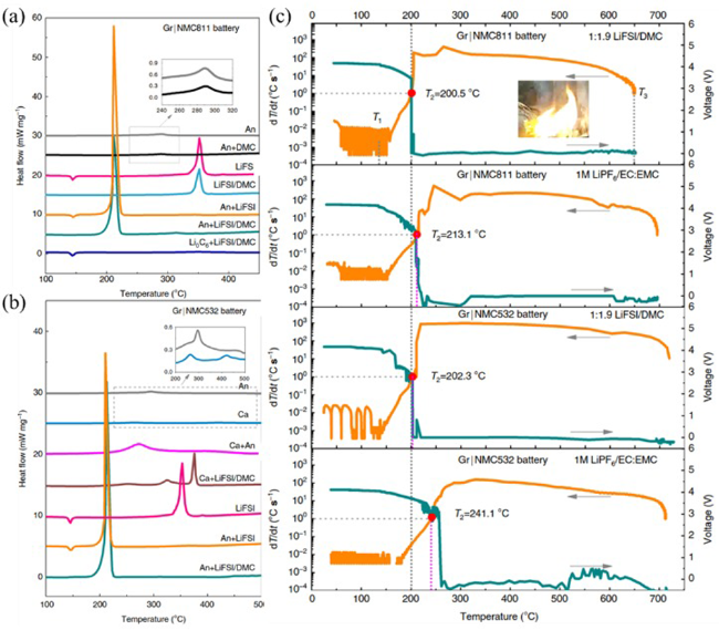
图14 (a) 采用高浓电解液 LiFSI/DMC 的 NCM811/Gr 电池组分组合的 DSC 曲线;(b) 采用高浓电解液 LiFSI/DMC 的 NCM523/Gr 电池组分组合的 DSC 曲线;(c) 高浓电解液LiFSI/DMC 与 1 M LiPF6/EC:EMC 电解液对 NCM/Gr 电池热失控特性的比较[134]

Fig.14 (a) DSC curves of components and their mixtures of NCM811/Gr battery using concentrated LiFSI/DMC electrolyte; (b) DSC curves of components and their mixtures of NCM523/Gr battery using concentrated LiFSI/DMC electrolyte; (c) comparison of thermal runaway features of NCM/Gr batteries with concentrated LiFSI/DMC and conventional 1 M LiPF6/EC:EMC electrolyte[136]

The addition of appropriate additives to the electrolyte can significantly improve the thermal stability of the battery, but the leakage of the electrolyte will still cause potential safety hazards. Resolving battery failures, such as leaks and internal shorts, requires further development of solid-state electrolytes. Hoang et al. Of Sungkywan University in Korea proposed an optimized design of a high-voltage stable solid-state lithium battery system by combining a solid-state electrolyte composed of PVA-g-PCA and HTpca nanoconductors with a Al2O3 coating LCO active material[139]. The PVA-g-PCA-80IL-5 HTpca solid state electrolyte has good ionic conductivity at room temperature with a (4.78·10-3S·cm-1),Li+ transfer number of 0.72 and a wide electrochemical window of up to 5.17 V vs Li+/Li. Cells cycled 500 times against a metallic Li negative electrode using a PVA-g-PCA-60IL-5HTpca prepared positive electrode maintained long-term stability and low interfacial resistance. As a conductive binder, PVA-g-PCA-60IL-5HTpca ensures the dense filling and uniform distribution of LCO particles, as well as the excellent adhesion strength (> 24 MPa) with the current collector. The solid-state lithium battery assembled with the LCO active material coated with Al2O3 has a specific capacity of 188.7 mAh·g-1 and can be cycled more than 200 times at 4.5 V and 60 ° C. Chen et al., Institute of Physics, Chinese Academy of Sciences, combined with EIS and X-CT analysis, found that lithium metal can penetrate into the defect sites of LATP bulk phase at high temperature[140]. The high reactivity of lithium and LATP at the defect site leads to higher interfacial reactivity and earlier thermal runaway. The thermal runaway can be significantly delayed by adding LiPO2F2 to modify the defect sites (atomic structural defects, cracks, voids, etc.) of LATP particles and inhibit the Li/SE interfacial reaction. The key to the development of solid electrolyte is to give full play to the advantages of high safety, improve technology and reduce costs.

5.5 Modified current collector

The role of current collectors in batteries is to provide electron conduction pathways for the positive and negative electrodes, and metals such as aluminum and copper are commonly used, which are electrochemically stable within the potential window, thus preventing degradation. However, the joining of the two most conductive materials within the cell causes the most severe internal short circuit and is one of the conditions for thermal runaway to occur. Therefore, removing or isolating the current collector during an internal short circuit can significantly reduce the risk of thermal runaway triggering and propagation.
Pham et al., University of London, reported a metal-coated polymer current collector[141]. In the pin-prick test, the cell with the aluminum-coated polymer current collector was 100% successful in preventing thermal runaway, keeping the cell voltage > 4 V, while the comparison cell eventually developed thermal runaway. Professor Cui Yi's team developed a lightweight polyimide-based current collector with a thickness of about 9 μm to replace the existing metal current collector[142]. The novel current collector has a sandwich structure, in which the middle layer is an organic supporting membrane embedded with a flame retardant, and the outer layer is a metal layer with a thickness of about 500 nm. The metal layer with the thickness can achieve the same conductivity as the metal foil current collector in the battery, and the polymer substrate has good thermal stability and mechanical strength. In the case of thermal runaway, based on the different temperature coefficient between the metal layer and the organic matter, the flame retardant is released, which can effectively prevent the battery from continuing to burn.
To sum up, the future research and design of lithium-ion batteries will mainly focus on the development of high thermal stability of positive electrode, high potential of negative electrode, high temperature resistance of separator, low flammability of electrolyte, solid state of electrolyte and multi-functional current collector.

6 Conclusion and prospect

The safety issue related to battery thermal runaway is a very complex process involving chemistry, materials science, and engineering, which needs to be considered from electrode materials, electrolytes, to battery design. Different electrode materials, electrolytes and battery types show different thermal runaway behaviors, and the reaction is also affected by the state of charge, working conditions and other factors. To reveal the coupling relationship between all these reactions and clarify the thermal runaway mechanism of different types of batteries, continuous research is needed.
For model research, establishing a model that can predict the electrochemical-thermal characteristics of the battery under different operating conditions, and analyzing and calculating it, is the key to thermal management and solving the problems of thermal performance, heat generation and heat dissipation at all levels of the battery system. The research on thermal runaway prediction model should start from the internal chemical reaction of the battery, obtain the kinetic parameters of different component combinations, and constantly enrich the database to make the model more accurate and universal.
Compared with improving the thermal management system, the use of intrinsically safe and stable materials is more conducive to solving the safety problems of lithium-ion batteries from the source. The positive and negative electrode materials, separator, electrolyte and current collector of the battery are very important to the thermal stability of the battery. But striking a balance between electrochemical performance and thermal stability is a tough choice. For the positive electrode, doping, coating and microstructure design are used to improve the safety. For the negative electrode, surface coating and film-forming additives were used to improve the stability of the SEI film. For electrolyte, adding flame retardant, using solid electrolyte, ionic liquid and redox clamp preparation, etc.; The mechanical strength and thermal stability of the diaphragm shall be improved as much as possible; For the current collector, a new type of current collector with multi-layer structure should be developed to suppress the internal short circuit caused by abnormal working conditions.
In a word, the heat production characteristics of the battery under different working conditions are analyzed, the triggering mechanism and chain reaction of thermal runaway are sorted out, and the causes of irreversible exothermic reaction between the components of the battery monomer are clarified.It is of great significance to study the modification strategies of cathode, anode, separator, electrolyte and current collector to improve the intrinsic safety of lithium-ion batteries and prevent thermal runaway.
[1]
Wang Q S, Mao B B, Stoliarov S I, Sun J H. Prog. Energy Combust. Sci., 2019, 73: 95.

[2]
Shan X Y, Li F, Wang D W, Cheng H M. Energy Storage Mater., 2016, 3: 66.

[3]
Feng X N, Ouyang M G, Liu X, Lu L G, Xia Y, He X M. Energy Storage Mater., 2018, 10: 246.

[4]
Goodenough J B, Kim Y. Chem. Mater., 2010, 22(3): 587.

[5]
Wang Q S, Ping P, Zhao X J, Chu G Q, Sun J H, Chen C H. J. Power Sources, 2012, 208: 210.

[6]
Spotnitz R, Franklin J. J. Power Sources, 2003, 113(1): 81.

[7]
Bernardi D, Pawlikowski E, Newman J. J. Electrochem. Soc., 1985, 132(1): 5.

[8]
Rao L, Newman J. J. Electrochem. Soc., 1997, 144(8): 2697.

[9]
Kim U S, Kwon K H, Shin C B, Kang T H, Kim C S. Meet. Abstr., 2006, MA2005-01(3): 178.

[10]
Kim U S, Shin C B, Kim C S. J. Power Sources, 2008, 180(2): 909.

[11]
Mao Y, Guo R, Sheng L M, Ma S D, Zhou L Z, Yan L Q, Yang C, Xie J Y. J. Electrochem. Soc., 2021, 168(6): 060553.

[12]
Liu S B, Zhang H Y, Xu X B. J. Energy Storage, 2021, 36: 102446.

[13]
Wang Q S, Jiang L H, Yu Y, Sun J H. Nano Energy, 2019, 55: 93.

[14]
Feng X N, Zheng S Q, Ren D S, He X M, Wang L, Liu X, Li M G, Ouyang M G. Energy Procedia, 2019, 158: 4684.

[15]
Zhao L W, Watanabe I, Doi T, Okada S, Yamaki J I, J. Power Sources, 2006, 161(2): 1275.

[16]
Richard M N, Dahn J R. J. Electrochem. Soc., 1999, 146(6): 2068.

[17]
Aurbach D, Zaban A, Ein-Eli Y, Weissman I, Chusid O, Markovsky B, Levi M, Levi E, Schechter A, Granot E. J. Power Sources, 1997, 68(1): 91.

[18]
Andersson A M, Herstedt M, Bishop A G, Edström K. Electrochimica Acta, 2002, 47(12): 1885.

[19]
Zhang L P, Li X L, Yang M R, Chen W H. Energy Storage Mater., 2021, 41: 522.

[20]
Mao B B, Chen H D, Cui Z X, Wu T Q, Wang Q S. Int. J. Heat Mass Transf., 2018, 122: 1103.

[21]
Feng X N, He X M, Ouyang M, Lu L G, Wu P, Kulp C, Prasser S. Appl. Energy, 2015, 154: 74.

[22]
Jiang J, Dahn J R. Electrochem. Commun., 2004, 6(1): 39.

[23]
Biensan P, Simon B, Peres J P. J. Power Sources, 1999, 81/82: 906.

[24]
Ping P, Kong D P, Zhang J Q, Wen R X, Wen J. J. Power Sources, 2018, 398: 55.

[25]
Wang Y D, Jiang J W, Dahn J R. Electrochem. Commun., 2007, 9(10): 2534.

[26]
Huang Y Q, Lin Y C, Jenkins D M, Chernova N A, Chung Y, Radhakrishnan B, Chu I H, Fang J, Wang Q, Omenya F, Ong S P, Stanley Whittingham M. ACS Appl. Mater. Interfaces, 2016, 8(11): 7013.

[27]
Noh H J, Youn S, Yoon C S, Sun Y K. J. Power Sources, 2013, 233: 121.

[28]
Dahbi M, Saadoune I, Gustafsson T, Edström K. Solid State Ion., 2011, 203(1): 37.

[29]
Cho Y H, Jang D, Yoon J, Kim H, Ahn T K, Nam K W, Sung Y E, Kim W S, Lee Y S, Yang X Q, Yoon W S. J. Alloys Compd., 2013, 562: 219.

[30]
Nam K W, Yoon W S, Yang X Q. J. Power Sources, 2009, 189(1): 515.

[31]
Röder P, Baba N, Wiemhöfer H D. J. Power Sources, 2014, 248: 978.

[32]
Johannes M D, Swider-Lyons K, Love C T. Solid State Ion., 2016, 286: 83.

[33]
Zhang Z, Fouchard D, Rea J R. J. Power Sources, 1998, 70(1): 16.

[34]
Wang Q S, Sun J H, Chen C H. J. Electrochem. Soc., 2007, 154(4): A263.

[35]
Li S Q, Meng X Y, Yi Q, Alonso J A, Fernandez-Diaz M T, Sun C W, Wang Z L. Nano Energy, 2018, 52: 510.

[36]
Zaghib K, Dube J, Dallaire A, Galoustov K, Guerfi A, Ramanathan M, Benmayza A, Prakash J, Mauger A, Julien C M. J. Power Sources, 2012, 219: 36.

[37]
Röder P, Baba N, Friedrich K A, Wiemhöfer H D. J. Power Sources, 2013, 236: 151.

[38]
Golubkov A W, Fuchs D, Wagner J, Wiltsche H, Stangl C, Fauler G, Voitic G, Thaler A, Hacker V. RSC Adv., 2014, 4(7): 3633.

[39]
Padhi A K, Nanjundaswamy K S, Goodenough J B. J. Electrochem. Soc., 1997, 144(4): 1188.

[40]
Ping P, Wang Q S, Huang P F, Li K, Sun J H, Kong D P, Chen C H. J. Power Sources, 2015, 285: 80.

[41]
Feng X N, Zheng S Q, Ren D S, He X M, Wang L, Cui H, Liu X, Jin C Y, Zhang F S, Xu C S, Hsu H, Gao S, Chen T Y, Li Y L, Wang T Z, Wang H, Li M G, Ouyang M. Appl. Energy, 2019, 246: 53.

[42]
Feng X N, Ren D S, He X M, Ouyang M G. Joule, 2020, 4(4): 743.

[43]
Xu C S, Feng X N, Huang W S, Duan Y K, Chen T Y, Gao S, Lu L G, Jiang F C, Ouyang M G. J. Energy Storage, 2020, 31: 101670.

[44]
Feng X N, Fang M, He X M, Ouyang M G, Lu L G, Wang H, Zhang M X. J. Power Sources, 2014, 255: 294.

[45]
Wang H B, Du Z M, Rui X Y, Wang S Y, Jin C Y, He L, Zhang F S, Wang Q Z, Feng X N. J. Hazard. Mater., 2020, 393: 122361.

[46]
Liu X, Ren D S, Hsu H, Feng X N, Xu G L, Zhuang M H, Gao H, Lu L G, Han X B, Chu Z Y, Li J Q, He X M, Amine K, Ouyang M. Joule, 2018, 2(10): 2047.

[47]
Bak S M, Hu E Y, Zhou Y N, Yu X Q, Senanayake S D, Cho S J, Kim K B, Chung K Y, Yang X Q, Nam K W. ACS Appl. Mater. Interfaces, 2014, 6(24): 22594.

[48]
Li Y, Liu X, Wang L, Feng X N, Ren D S, Wu Y, Xu G L, Lu L G, Hou J X, Zhang W F, Wang Y L, Xu W Q, Ren Y, Wang Z F, Huang J Y, Meng X F, Han X B, Wang H W, He X M, Chen Z H, Amine K, Ouyang M. Nano Energy, 2021, 85: 105878.

[49]
Hou J X, Feng X N, Wang L, Liu X, Ohma A, Lu L G, Ren D S, Huang W S, Li Y, Yi M C, Wang Y, Ren J Q, Meng Z H, Chu Z Y, Xu G L, Amine K, He X M, Wang H W, Nitta Y, Ouyang M. Energy Storage Mater., 2021, 39: 395.

[50]
Wu Y, Ren D S, Liu X, Xu G L, Feng X N, Zheng Y J, Li Y L, Yang M, Peng Y, Han X B, Wang L, Chen Z H, Ren Y, Lu L G, He X M, Chen J T, Amine K, Ouyang M G. Adv. Energy Mater., 2021, 11: 1.

[51]
Ren D S, Feng X N, Liu L S, Hsu H, Lu L G, Wang L, He X M, Ouyang M. Energy Storage Mater., 2021, 34: 563.

[52]
Zheng Y J, Shi Z H, Ren D S, Chen J, Liu X, Feng X N, Wang L, Han X B, Lu L G, He X M, Ouyang M G. J. Energy Chem., 2022, 69: 593.

[53]
Zhong G B, Mao B B, Wang C, Jiang L, Xu K Q, Sun J H, Wang Q S. J. Therm. Anal. Calorim., 2019, 135(5): 2879.

[54]
Mao B B, Huang P F, Chen H D, Wang Q S, Sun J H. Int. J. Heat Mass Transf., 2020, 149: 119178.

[55]
Huang P F, Yao C X, Mao B B, Wang Q S, Sun J H, Bai Z H. Energy, 2020, 213: 119082.

[56]
Huang L, Xu G J, Du X F, Li J D, Xie B, Liu H S, Han P X, Dong S M, Cui G L, Chen L Q. Adv. Sci., 2021, 8(14): 2100676.

[57]
Janek J, Zeier W G. Nat. Energy, 2016, 1(9): 16141.

[58]
Albertus P, Anandan V, Ban C M, Balsara N, Belharouak I, Buettner-Garrett J, Chen Z H, Daniel C, Doeff M, Dudney N J, Dunn B, Harris S J, Herle S, Herbert E, Kalnaus S, Libera J A, Lu D P, Martin S, McCloskey B D, McDowell M T, Meng Y S, Nanda J, Sakamoto J, Self E C, Tepavcevic S, Wachsman E, Wang C S, Westover A S, Xiao J, Yersak T. ACS Energy Lett., 2021, 1399.

[59]
Chen R S, Nolan A M, Lu J Z, Wang J Y, Yu X Q, Mo Y F, Chen L Q, Huang X J, Li H. Joule, 2020, 4(4): 812.

[60]
Yan J T, Zhu D D, Ye H J, Sun H M, Zhang X D, Yao J M, Chen J Z, Geng L, Su Y, Zhang P, Dai Q S, Wang Z F, Wang J, Zhao J, Rong Z Y, Li H, Guo B Y, Ichikawa S, Gao D W, Zhang L Q, Huang J Y, Tang Y F. ACS Energy Lett., 2022, 7(11): 3855.

[61]
Wang J G, Mei W X, Cui Z X, Shen W X, Duan Q L, Jin Y, Nie J B, Tian Y, Wang Q S, Sun J H. Appl. Therm. Eng., 2020, 171: 115082.

[62]
Xu J J, Mei W X, Zhao C P, Liu Y J, Zhang L, Wang Q S. J. Therm. Anal. Calorim., 2021, 144(2): 273.

[63]
Huang S, Du X N, Richter M. J. Electrochem. Soc., 2020, 167: 090526.

[64]
Zhu X Q, Wang H, Wang X, Gao Y F, Allu S, Cakmak E, Wang Z P. J. Power Sources, 2020, 455: 227939.

[65]
Lee D C, Kim C W. J. Power Sources, 2020, 475: 228678.

[66]
Zhu X Q, Wang Z P, Wang Y T, Wang H, Wang C, Tong L, Yi M. Energy, 2019, 169: 868.

[67]
Zhu X Q, Wang Z P, Wang C, Huang L W. J. Electrochem. Soc., 2018, 165(16): A3613.

[68]
Ye J N, Chen H D, Wang Q S, Huang P F, Sun J H, Lo S. Appl. Energy, 2016, 182: 464.

[69]
Ren D S, Feng X N, Lu L G, He X M, Ouyang M G. Appl. Energy, 2019, 250: 323.

[70]
Liu J L, Duan Q L, Ma M N, Zhao C P, Sun J H, Wang Q S. J. Power Sources, 2020, 445: 227263.

[71]
Togasaki N, Yokoshima T, Osaka T. J. Electrochem. Soc., 2022, 169(3): 030547.

[72]
Zhang L L, Ma Y L, Cheng X Q, Du C Y, Guan T, Cui Y Z, Sun S, Zuo P J, Gao Y Z, Yin G P. J. Power Sources, 2015, 293: 1006.

[73]
Guo R, Lu L G, Ouyang M G, Feng X N. Sci. Rep., 2016, 6: 30248.

[74]
Lee D C, Lee J J, Kim J S, Cho S, Kim C W. Appl. Therm. Eng., 2020, 175: 115422.

[75]
Ouyang D X, Weng J W, Chen M Y, Liu J H, Wang J. Int. J. Energy Res., 2020, 44(1): 229.

[76]
Al-Hallaj S, Selman J R. J. Power Sources, 2002, 110(2): 341.

[77]
Wu M S, Liu K H, Wang Y Y, Wan C C. J. Power Sources, 2002, 109(1): 160.

[78]
Jeon D H, Baek S M. Energy Convers. Manag., 2011, 52(8/9): 2973.

[79]
Kim U S, Yi J, Shin C B, Han T, Park S. J. Electrochem. Soc., 2013, 160(6): A990.

[80]
Doyle M, Fuller T F, Newman J. J. Electrochem. Soc., 1993, 140(6): 1526.

[81]
Fuller T F, Doyle M, Newman J. J. Electrochem. Soc., 1994, 141(1): 1.

[82]
Pals C R, Newman J. J. Electrochem. Soc., 1995, 142(10): 3274.

[83]
Pals C R, Newman J. J. Electrochem. Soc., 1995, 142(10): 3282.

[84]
Madani S, Schaltz E, Knudsen Kær S. Batteries, 2018, 4(2): 20.

[85]
Mastali M, Foreman E, Modjtahedi A, Samadani E, Amirfazli A, Farhad S, Fraser R A, Fowler M. Int. J. Therm. Sci., 2018, 129: 218.

[86]
Lai Y Q, Du S L, Ai L, Ai L H, Cheng Y, Tang Y W, Jia M. Int. J. Hydrog. Energy, 2015, 40(38): 13039.

[87]
He C X, Yue Q L, Wu M C, Chen Q, Zhao T S. Int. J. Heat Mass Transf., 2021, 181: 121855.

[88]
Ren H L, Jia L, Dang C, Qi Z L. J. Energy Storage, 2022, 50: 104277.

[89]
Jiang G W, Zhuang L, Hu Q H, Liu Z Q, Huang J H. Appl. Therm. Eng., 2020, 171: 115080.

[90]
Bahiraei F, Ghalkhani M, Fartaj A, Nazri G A. Appl. Therm. Eng., 2017, 125: 904.

[91]
Samba A, Omar N, Gualous H, Capron O, Van den Bossche P, Van Mierlo J. Electrochimica Acta, 2014, 147: 319.

[92]
He T F, Zhang T, Wang Z R, Cai Q. Appl. Energy, 2022, 313: 118797.

[93]
Feng X N. Doctoral Dissertation of Tsinghua University, 2016.

冯旭宁. 清华大学博士论文, 2016.).

[94]
Hatchard T D, MacNeil D D, Basu A, Dahn J R. J. Electrochem. Soc., 2001, 148(7): A755.

[95]
Kim G H, Pesaran A, Spotnitz R. J. Power Sources, 2007, 170(2): 476.

[96]
Ren D S, Liu X, Feng X N, Lu L G, Ouyang M G, Li J Q, He X M. Appl. Energy, 2018, 228: 633.

[97]
Wang Y, Ren D S, Feng X N, Wang L, Ouyang M G. Appl. Energy, 2022, 306: 117943.

[98]
Chombo P V, Laoonual Y. J. Power Sources, 2020, 478: 228649.

[99]
Liu K, Liu Y Y, Lin D C, Pei A, Cui Y. Sci. Adv., 2018, 4(6): eaas9820.

[100]
Zhou F, Zhao X M, Dahn J R. J. Electrochem. Soc., 2010, 157(7): A798.

[101]
Zhou F, Zhao X M, Jiang J W, Dahn J R. Electrochem. Solid-State Lett., 2009, 12(4): A81.

[102]
Hilgers M, Achenbach W. Hybrid Vehicles. Alternative Powertrains and Extensions to the Conventional Powertrain, 2021.

[103]
Cho W, Kim S M, Song J H, Yim T, Woo S G, Lee K W, Kim J S, Kim Y J. J. Power Sources, 2015, 282: 45.

[104]
Lee D J, Scrosati B, Sun Y K. J. Power Sources, 2011, 196(18): 7742.

[105]
Ji W X, Wang F, Liu D T, Qian J F, Cao Y L, Chen Z X, Yang H X, Ai X P. J. Mater. Chem. A, 2016, 4(29): 11239.

[106]
Xia L, Li S L, Ai X P, Yang H X, Cao Y L. Energy Environ. Sci., 2011, 4(8): 2845.

[107]
Naguib M, Allu S, Simunovic S, Li J L, Wang H, Dudney N J. Joule, 2018, 2(1): 155.

[108]
Ding F, Xu W, Choi D, Wang W, Li X L, Engelhard M H, Chen X L, Yang Z G, Zhang J G. J. Mater. Chem., 2012, 22(25): 12745.

[109]
Lee M L, Li Y H, Liao S C, Chen J M, Yeh J W, Shih H C. Appl. Surf. Sci., 2012, 258(16): 5938.

[110]
Eom J Y, Cho Y H, Kim S I, Han D, Sohn D. J. Alloys Compd., 2017, 723: 456.

[111]
Gao K, Li S D. J. Power Sources, 2014, 270: 304.

[112]
Zhang H Y, Chen Y T, Li J, He C H, Chen Y M. Int. J. Hydrog. Energy, 2014, 39(28): 16096.

[113]
Ren B, Li W, Wei A J, Bai X, Zhang L H, Liu Z F. J. Alloys Compd., 2018, 740: 784.

[114]
Chen Y T, Zhang H Y, Li Y Y, Chen Y M, Luo T. Int. J. Hydrog. Energy, 2017, 42(10): 7195.

[115]
Lee H, Yanilmaz M, Toprakci O, Fu K, Zhang X W. Energy Environ. Sci., 2014, 7(12): 3857.

[116]
Kong L X, Li C, Jiang J C, Pecht M. Energies, 2018, 11(9): 2191.

[117]
Jeong H S, Lee S Y. J. Power Sources, 2011, 196(16): 6716.

[118]
Choudhury S, Azizi M, Raguzin I, Göbel M, Michel S, Simon F, Willomitzer A, Mechtcherine V, Stamm M, Ionov L. Phys. Chem. Chem. Phys., 2017, 19(18): 11239.

[119]
Miao Y E, Zhu G N, Hou H Q, Xia Y Y, Liu T X. J. Power Sources, 2013, 226: 82.

[120]
Kim J K, Niedzicki L, Scheers J, Shin C R, Lim D H, Wieczorek W, Johansson P, Ahn J H, Matic A, Jacobsson P. J. Power Sources, 2013, 224: 93.

[121]
Liu L, Park J, Lin X K, Sastry A M, Lu W. J. Power Sources, 2014, 268: 482.

[122]
Long M C, Duan P H, Gao Y, Wang X L, Wu G, Wang Y Z. Chem. Eng. J., 2022, 432: 134394.

[123]
Min Y, Guo L, Wei G Y, Xian D X, Zhang B, Wang L. Chem. Eng. J., 2022, 443: 136480.

[124]
Baginska M, Blaiszik B J, Merriman R J, Sottos N R, Moore J S, White S R. Adv. Energy Mater., 2012, 2(5): 583.

[125]
Li H, Wu D B, Wu J, Dong L Y, Zhu Y J, Hu X L. Adv. Mater., 2017, 29(44): 1703548.

[126]
Liu K, Liu W, Qiu Y C, Kong B, Sun Y M, Chen Z, Zhuo D, Lin D C, Cui Y. Sci. Adv., 2017, 3(1): e1601978.

[127]
Chou L Y, Ye Y S, Lee H K, Huang W X, Xu R, Gao X, Chen R J, Wu F, Tsung C K, Cui Y. Nano Lett., 2021, 21(5): 2074.

[128]
Wang Y, Mao Y, Bai Q Y, Li C L, Guo R, Xie J Y. Solid State Ion., 2019, 337: 7.

[129]
Wang W, Liao C, Liu L X, Cai W, Yuan Y, Hou Y B, Guo W W, Zhou X, Qiu S L, Song L, Kan Y C, Hu Y. J. Power Sources, 2019, 420: 143.

[130]
Xia L, Xia Y G, Wang C S, Hu H S, Lee S X, Yu Q, Chen H C, Liu Z P. ChemElectroChem, 2015, 2(11): 1707.

[131]
Wang J H, Yamada Y, Sodeyama K, Watanabe E, Takada K, Tateyama Y, Yamada A. Nat. Energy, 2018, 3(1): 22.

[132]
Zeng Z Q, Murugesan V, Han K S, Jiang X Y, Cao Y L, Xiao L F, Ai X P, Yang H X, Zhang J G, Sushko M L, Liu J. Nat. Energy, 2018, 3(8): 674.

[133]
Wang J H, Yamada Y, Sodeyama K, Chiang C H, Tateyama Y, Yamada A. Nat. Commun., 2016, 7: 12032.

[134]
Hou J X, Lu L G, Wang L, Ohma A, Ren D S, Feng X N, Li Y, Li Y L, Ootani I, Han X B, Ren W N, He X M, Nitta Y, Ouyang M. Nat. Commun., 2020, 11: 5100.

[135]
Ren X D, Chen S R, Lee H, Mei D H, Engelhard M H, Burton S D, Zhao W G, Zheng J M, Li Q Y, Ding M S, Schroeder M, Alvarado J, Xu K, Meng Y S, Liu J, Zhang J G, Xu W. Chem, 2018, 4(8): 1877.

[136]
Chen S R, Zheng J M, Mei D H, Han K S, Engelhard M H, Zhao W G, Xu W, Liu J, Zhang J G. Adv. Mater., 2018, 30(21): 1706102.

[137]
Chen S R, Zheng J M, Yu L, Ren X D, Engelhard M H, Niu C J, Lee H, Xu W, Xiao J, Liu J, Zhang J G. Joule, 2018, 2(8): 1548.

[138]
Wu Y, Feng X N, Yang M, Zhao C Z, Liu X, Ren D S, Ma Z, Lu L G, Wang L, Xu G L, He X M, Amine K, Ouyang M. Adv. Sci., 2022, 9(32): 2204059.

[139]
Hoang H A, Kim D. Chem. Eng. J., 2022, 435: 135092.

[140]
Chen R S, Yao C X, Yang Q, Pan H Y, Yu X Q, Zhang K, Li H. ACS Appl. Mater. Interfaces, 2021, 13(16): 18743.

[141]
Pham M T M, Darst J J, Walker W Q, Heenan T M M, Cell Rep. Phys. Sci., 2021, 2: 100360.

[142]
Ye Y S, Chou L Y, Liu Y Y, Wang H S, Lee H K, Huang W X, Wan J Y, Liu K, Zhou G M, Yang Y F, Yang A K, Xiao X, Gao X, Boyle D T, Chen H, Zhang W B, Kim S C, Cui Y. Nat. Energy, 2020, 5(10): 786.

Outlines

/