
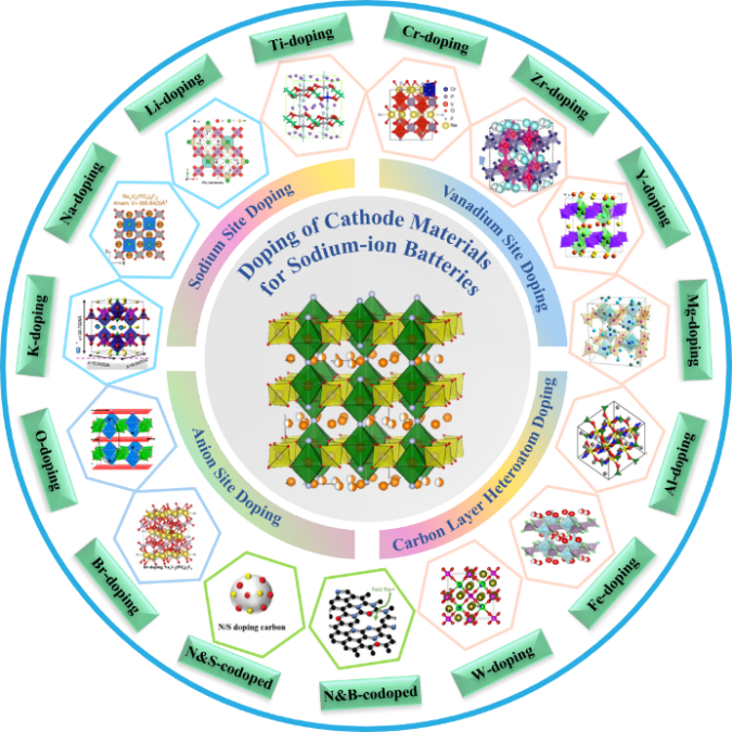
Doping Modification of Sodium Vanadium Fluorophosphate as Cathode Material for Sodium Ion Batteries
Received date: 2024-05-08
Revised date: 2024-10-17
Online published: 2025-03-10
Supported by
Yunnan Province Nonferrous Metals Vacuum Metallurgy Top Team(202305AS350012)
Basic Research Program of Yunnan Provincial(202301BE070001-014)
Basic Research Program of Yunnan Provincial(202301AT070150)
With excellent multiplication performance, stable high and low-temperature performance, abundant sodium resources and low cost, sodium-ion batteries have good application prospects in the field of large-scale energy storage and low-speed electric vehicles. The cathode material determines the working voltage and cycling performance of sodium-ion batteries, and is the core component that directly affects the overall performance of sodium-ion batteries. Among them, Na3V2(PO4)2F3 (NVPF) has excellent structural stability and high working potential, but slow ion diffusion and low electronic conductivity, which need to be further improved by elemental doping and other modification means. This paper has introduced the background, crystal structure and preparation method of NVPF. Has summarized in detail the modification progress of doping at different doping sites, such as sodium, vanadium, and anionic sites in NVPF materials. The mechanisms of doping in NVPF materials were analyzed, which can optimize the particle size, enhance the lattice stability, change the lattice spacing to enhance the diffusion rate of sodium ions, and increase the electronic conductivity. Based on the above, this paper summarized the preparation, doping sites and effects of NVPF materials from the perspective of subsequent research, and have also looked ahead to the future prospects of doping modification.
1 Research background
2 Structural mechanism and preparation of vanadium sodium fluorophosphate
2.1 Structural Characteristics
2.2 Preparation methods
3 Doping modification of sodium vanadium fluorophosphate at different sites
3.1 Sodium site doping
3.2 Vanadium site doping
3.3 Anion site doping
3.4 Carbon layer heteroatom doping
4 Study on the doping mechanism of sodium vanadium fluorophosphate
4.1 Suppresses particle agglomeration and optimizes particle size
4.2 Enhance structural stability
4.3 Changing the lattice spacing to enhance ion diffusion rate
4.4 Improve the electronic conductivity
5 Summary and outlook
Fangcheng Hu , Junxian Hu , Yang Tian , Dong Wang , Tingzhuang Ma , Lipeng Wang . Doping Modification of Sodium Vanadium Fluorophosphate as Cathode Material for Sodium Ion Batteries[J]. Progress in Chemistry, 2025 , 37(3) : 439 -454 . DOI: 10.7536/PC240508
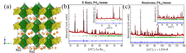
图1 (a) Crystal Structure of NVPF with Tetragonal Space Group P42/mnm [41]; (b) Refined XRD Pattern of Tetragonal Space Group P42/mnm [41]; (c) Refined Neutron Diffraction Pattern of Tetragonal Space Group P42/mnm [41]Fig. 1 (a) Crystal structure of the tetragonal space group P42/mnm of NVPF[41]; (b) rietveld refined XRD patterns of the tetragonal space group P42/mnm [41]; (c) rietveld refined neutron diffraction patterns of the tetragonal space group P42/mnm [41] |
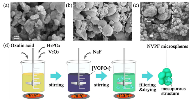
图2 (a) HRTEM Image of NVPF@C Material Prepared by High-Temperature Solid-State Method[48]; (b) SEM Image of NVPF@C Material Prepared by Hydrothermal Method[1]; (c) SEM Image of NVPF@C Material Prepared by Sol-Gel Method[54]; (d) Schematic Diagram of NVPF@C Preparation by Sol-Gel Method[54]Fig. 2 (a) HRTEM image of NVPF@C material prepared by high-temperature solid-phase method[48]; (b) SEM image of NVPF@C material prepared by hydrothermal method[1]; (c) SEM image of NVPF@C material prepared by sol-gel method[54]; (d) schematic diagram of NVPF@C prepared by sol-gel method[54] |
表1 NVPF的掺杂改性策略研究Table 1 Research of NVPF doping modification strategies |
| Cathode material | Doping sites | Element | Capacity (mAh·g-1) | Cycle performance | Ref |
|---|---|---|---|---|---|
| Na4V2(PO4)2F3 | Na | Na | 0.2 C 130 | 0.2 C 100% (after 20 cycle) | 55 |
| Na2.9K0.1V2(PO4)3F3 | Na | K | 0.1 C 120.8 | 1 C 97.5% (after 500 cycle) | 56 |
| Na0.92K0.08V2(PO4)2F3@CNT | Na | K | 1 C 120 | 50 C 90% (after 6000 cycle) | 53 |
| Na3- x Li x V2(PO4)2F3 | Na | Li | 0.2 C 106 | 20 C 80% (after 25 cycle) | 57 |
| Na3V1.93Al0.07(PO4)2F3 | V | Al | 0.1 C 121.3 | 5 C 75% (after 400 cycle) | 58 |
| Na3V1.95Mn0.05(PO4)2F3/C | V | Mn | 0.2 C 122.9 | 0.2 C 99.1% (after 500 cycle) | 59 |
| Na3V1.98Mn0.02(PO4)2F3@C | V | Mn | 0.5 C 79.9 | 1 C 81.9% (after 1000 cycle) | 60 |
| Na3V1.97Fe0.03(PO4)2F3/C | V | Fe | 0.1 C 126.7 | 0.2 C 97.1% (after 100 cycle) | 61 |
| Na3V1.95Cr0.05(PO4)2F3/C | V | Cr | 10C 101.9 | 10 C 68.7% (after 1000 cycle) | 62 |
| Na3V1.98Zr0.02(PO4)2F3/NC | V | Zr | 0.5 C 119.2 | 20 C 90.2 % (after 1000 cycle) | 63 |
| Na3V1.95Ca0.05(PO4)2F3/C | V | Ca | 1 C 124 | 10 C 70 % (after 1000 cycle) | 64 |
| Na3V1.97Cr0.03(PO4)2F3@C | V | Cr | 0.5 C 111 | 2 C 93% (after 125 cycle) | 65 |
| Na3V1.9Fe0.1(PO4)2F3@N-CNTs | V | Fe | 0.1 C 105 | 2 C 74.53% (after 1000 cycle) | 66 |
| Na3V1.95Mg0.05(PO4)2F3/C | V | Mg | 10 C 80 | 10 C 88% (after 500 cycle) | 67 |
| Na3V1.9Y0.1(PO4)2F3/C | V | Y | 0.5 C 121.3 | 1 C 93.46% (after 200 cycle) | 68 |
| NVPF- | V | Ti | 1 C 117 | 40 C 91.3% (after 500 cycle) | 69 |
| Na3V1.96W0.04(PO4)2F3@C | V | W | 0.1 C 153 | 2 C 97.4% (after 250 cycle) | 70 |
| Na3V1.9Co0.1(PO4)2F3 | V | Co | 0.1 C 111.3 | 5 C 70% (after 80 cycle) | 71 |
| Na3V2(PO4)2FBr2/C | Anion | Br | 1 C 116.1 | 10 C 98.3% (after 1000 cycle) | 72 |
| Na3V2O2(PO4)2F/rGO | Anion | O | 1 C 100.4 | 0.1 C 91.4% (after 200 cycle) | 73 |
| Na3V2O2(PO4)2F/MWCNT | Anion | O | 0.1 C 102 | 1 C 78% (after 400 cycle) | 74 |
| Na3V2O2 x (PO4)2F3-2 x | Anion | O | 1 C 100 | 0.5 C 93% (after 50 cycle) | 75 |
| Na3(VO1- x PO4)2F1+2 x | Anion | O | 0.2 C 112 | 2 C 73% (after 1200 cycle) | 76 |
| Na3V2(PO4)2F3/C-PDPA | Carbon | N | 0.5 C 113.8 | 10 C 95.8% (after 800 cycle) | 77 |
| Na3V2(PO4)2F3-PCNB-20 | Carbon | N&B | 0.5 C 109 | 0.5 C 93.2% (after 100 cycle) | 78 |
| Na3V2(PO4)2F3-NSC | Carbon | N&S | 10 C 83 | 5 C 92.1% (after 500 cycle) | 79 |
图3 (a) TEM Image of NVPFCa-0.05/C[64]; (b) TEM Image of Na3V1.95Mg0.05(PO4)2F3/C[67]; (c) HRTEM Image of Na3V2- x Zr x (PO4)2F3 [63]; (d) First Cycle Charge-Discharge of Na4V2(PO4)2F3 [55]; (e) Cycling Performance of NKVPF@CNT at 50 C Rate[53]; (f) Schematic Diagram of Na3V2- x Ti x (PO4)2F3Preparation[69]Fig. 3 (a) TEM image of NVPFCa-0.05/C[64]; (b) TEM image of Na3V1.95Mg0.05(PO4)2F3/C[67]; (c) HRTEM image of Na3V2- x Zr x (PO4)2F3 [63]; (d) First turn charging and discharging of Na4V2(PO4)2F3 [55]; (e) cycling performance of NKVPF@CNT at 50 C rate[53]; (f) schematic diagram of Na3V2- x Ti x (PO4)2F3 preparation[69] |
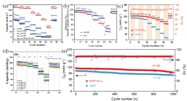
图4 (a) Rate Performance of Fe0.1-NVPF@N-CNT[66]; (b) Rate Performance of Na3V1.95Cr0.05(PO4)2F3/C[62]; (c) Rate Performance of Na3V1.98Mn0.02(PO4)2F3[60]; (d) Rate Performance of NVAlPF-0.07[58]; (e) Capacity of Na3V1.98Mn0.02(PO4)2F3 at 1 C after 1000 Cycles[60]Fig. 4 (a) Doubling performance of Fe0.1-NVPF@N-CNT[66]; (b) doubling performance of Na3V1.95Cr0.05(PO4)2F3/C[62]; (c) doubling performance of Na3V1.98Mn0.02(PO4)2F3 [60]; (d) doubling performance of NVAlPF-0.07[58]; (e) doubling performance of N Na3V1.98Mn0.02(PO4)2F3 capacity for 1000 cycles at 1 C[60] |
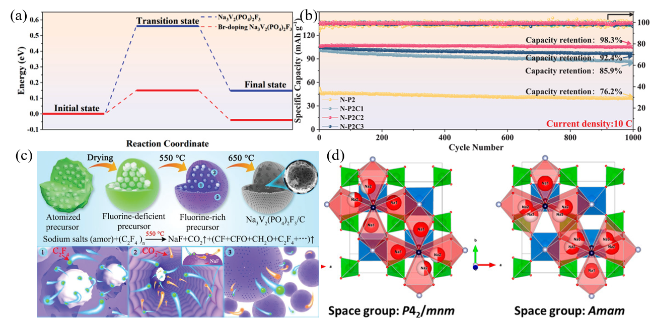
图5 (a) Diffusion Barrier After Incorporation of Br[72]; (b) Long Cycle Performance at 10 C after Br Doping[72]; (c) Schematic Diagram of Br-Doped Porous Carbon Sphere NVPF Preparation[72]; (d) Space Groups of Two Na+Distributions[89]Fig. 5 (a) Diffusion barrier after Br doping[72]; (b) 1000 long cycles performance at 10C after Br doping[72]; (c) Br-doped porous carbon spheres NVPF preparation schematic[72]; (d) space group of two Na+ distributions[89] |
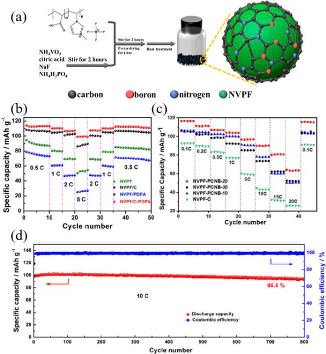
图6 (a) Schematic Diagram of NVPF-PCNB-20 Microsphere Preparation[78]; (b) Rate Performance of NVPF/C-PDPA at Different Rates[77]; (c) Rate Performance of NVPF-PCNB at Different Rates[78]; (d) Performance of NVPF/C-PDPA Cycled 800 Times at 10 C Rate[77]Fig. 6 (a) Schematic diagram of NVPF-PCNB-20 microsphere preparation[78]; (b) doubling performance of NVPF/C-PDPA at different rates[77]; (c) doubling performance of NVPF-PCNB at different rates[78]; (d) performance of NVPF/C-PDPA with 800 cycles at 10 C rate[77] |
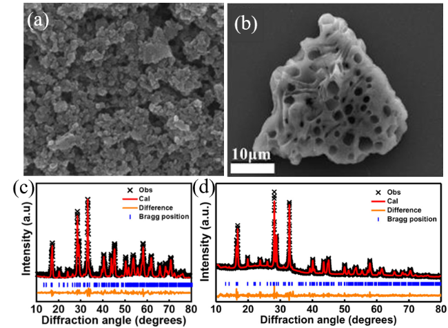
图7 (a) SEM Image of NVPF-Ca-0.05/C[64]; (b) EDS Mapping of NVPF-PCNB-20[78]; (c) Refined XRD Pattern of NVPF-Ca-0.05/C Material[64]; (d) Refined XRD Pattern of Na3V1.95Mg0.05(PO4)2F3/C Material[67]Fig. 7 (a) SEM image of NVPF-Ca-0.05/C[64]; (b) EDS mapping of NVPF-PCNB-20[78]; (c) XRD plots of NVPF-Ca-0.05/C material Rietveld after refinement[64]; (d) XRD plots of Na3V1.95Mg0.05(PO4)2F3/C material Rietveld after refinement[67] |
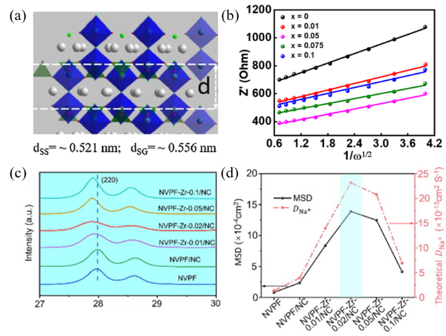
图8 (a) Lattice Spacing of Na4V2(PO4)2F3[55]; (b) and Inverse Function Plot of Na3V2-xCax(PO4)2F3/C[64]; (c) XRD Patterns of NVPF and NVPF-Zr-x/NC (x=0, 0.01, 0.02, 0.05, and 0.1) Samples[63]; (d) Kinetic Parameters of NVPF-Zr-0.02/NC[63]Fig. 8 (a) Lattice spacing of Na4V2(PO4)2F3 [55]; (b) versus inverse function image of Na3V2- x Ca x (PO4)2F3/C[64]; (c) XRD patterns of NVPF and NVPF-Zr-x/NC (x = 0, 0.01, 0.02, 0.05 and 0.1) samples[63]; (d) kinetic parameter map of NVPF-Zr-0.02/NC[63] |
| [1] |
|
| [2] |
(王跃生, 容晓晖, 徐淑银, 胡勇胜, 李泓, 陈立泉. 储能科学与技术, 2016, 5(3): 268.).
|
| [3] |
(曹余良. 储能科学与技术, 2020, 9(3): 757.).
|
| [4] |
|
| [5] |
|
| [6] |
|
| [7] |
|
| [8] |
|
| [9] |
|
| [10] |
|
| [11] |
|
| [12] |
|
| [13] |
|
| [14] |
|
| [15] |
|
| [16] |
|
| [17] |
|
| [18] |
|
| [19] |
|
| [20] |
|
| [21] |
|
| [22] |
|
| [23] |
|
| [24] |
|
| [25] |
|
| [26] |
|
| [27] |
|
| [28] |
|
| [29] |
|
| [30] |
|
| [31] |
|
| [32] |
|
| [33] |
|
| [34] |
|
| [35] |
|
| [36] |
|
| [37] |
|
| [38] |
|
| [39] |
|
| [40] |
|
| [41] |
|
| [42] |
|
| [43] |
|
| [44] |
|
| [45] |
|
| [46] |
|
| [47] |
|
| [48] |
|
| [49] |
|
| [50] |
|
| [51] |
(叶帆, 伍凌, 唐式豹, 杨柳, 钟胜奎. 人工晶体学报, 2019, 48(09): 1673.).
|
| [52] |
|
| [53] |
|
| [54] |
|
| [55] |
|
| [56] |
|
| [57] |
|
| [58] |
|
| [59] |
|
| [60] |
|
| [61] |
|
| [62] |
|
| [63] |
|
| [64] |
|
| [65] |
|
| [66] |
|
| [67] |
|
| [68] |
|
| [69] |
|
| [70] |
|
| [71] |
(高飞, 杨凯, 吕扬阳, 赵丽娜, 范茂松, 刘皓, 耿萌萌, 张明杰, 王凯丰. 合成材料老化与应用, 2019, 48(3): 54.).
|
| [72] |
|
| [73] |
|
| [74] |
|
| [75] |
|
| [76] |
|
| [77] |
|
| [78] |
|
| [79] |
|
| [80] |
|
| [81] |
(朱超, 涂健, 丁元力. 硅酸盐学报, 2022, 50(1): 158.).
|
| [82] |
|
| [83] |
|
| [84] |
|
| [85] |
|
| [86] |
|
| [87] |
|
| [88] |
|
| [89] |
|
| [90] |
|
/
| 〈 |
|
〉 |
