Home Journals Progress in Chemistry
Progress in Chemistry

Abbreviation (ISO4): Prog Chem      Editor in chief: Jincai ZHAO

About  /  Aim & scope  /  Editorial board  /  Indexed  /  Contact  / 
Review

The Photo-Assisted Strategy for High Performance Lithium-Sulfur Batteries

  • Jia-Cheng Yu 1 ,
  • Hao Su 1 ,
  • Jun Zhang , 2, * ,
  • Gang Xie 3 ,
  • Ming Yao , 1, * ,
  • Jin Qu , 1, *
Expand
  • 1 College of Material Science and Engineering,Beijing University of Chemical Technology,Beijing 100029,China
  • 2 High-tech Research Institute,Beijing University of Chemical Technology,Beijing 100029,China
  • 3 POWERCHINA BEIJING Engineering Co.,Ltd,Beijing 100024,China
*(Jin Qu);
(Ming Yao);
(Jun Zhang)

Received date: 2024-08-11

  Revised date: 2024-09-18

  Online published: 2025-03-10

Supported by

National Natural Science Foundation of China(52472085)

Abstract

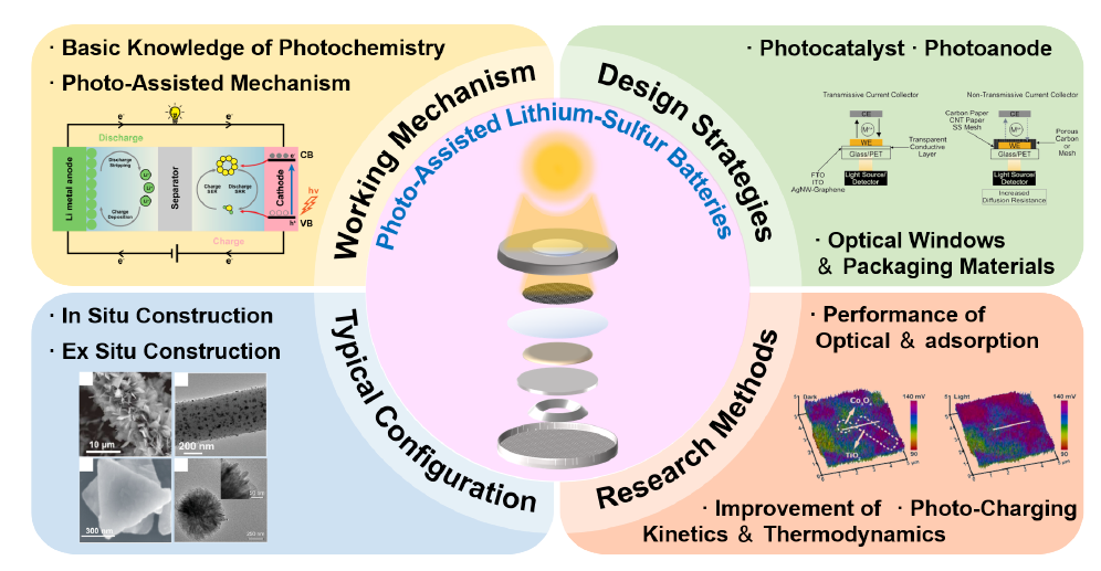
Lithium-sulfur batteries are valued for their high theoretical specific capacity,energy density,and other advantages,but their commercialization is limited by the slow kinetics of sulfur species conversion and the "shuttle effect". In response,researchers have utilized the photocatalytic effect to develop a photo-assisted strategy for lithium-sulfur batteries,an emerging strategy that not only improves the adsorption and catalytic performance of the catalyst,but also enhances the battery performance in terms of both thermodynamics and kinetics,and even achieves the storage and release of solar energy through the photo-charging mechanism. In this paper,based on recently relevant studies,we introduce in detail the photoelectrochemical principles of photo-assisted lithium-sulfur batteries,discuss the design strategies of photocatalysts and photoanode,as well as the selection of optical windows and encapsulation materials,and review the typical configurations of photopositives and the research methodology of photo-assisted lithium-sulfur batteries,with the aim of attracting the extensive attention of our peers and providing references for the in-depth understanding and improvement of photo-assisted lithium-sulfur batteries.

Contents

1 Introduction

2 The working mechanism and design strategy of photo-assisted lithium-sulfur batteries

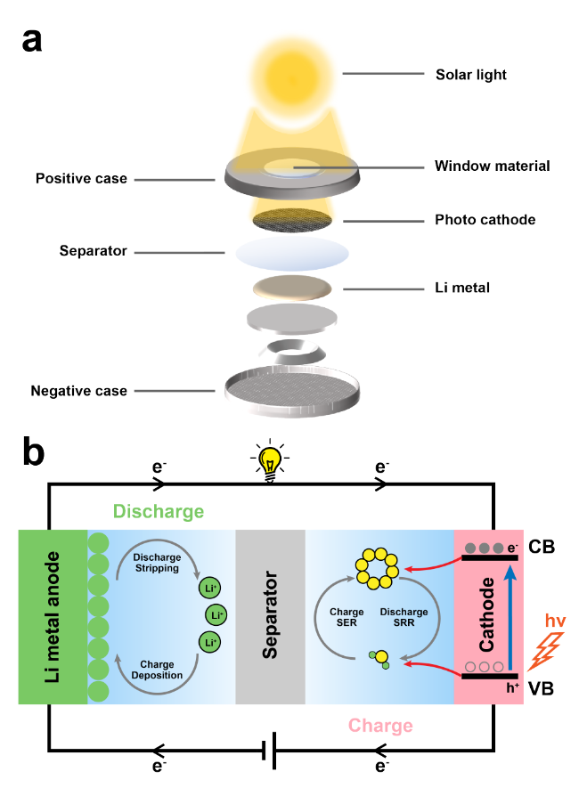
2.1 The photoelectrochemical principle of photo-assisted lithium-sulfur batteries

2.2 Design strategies of photo-assisted lithium-sulfur batteries

3 Typical configuration and research methods of photo-assisted lithium sulfur batteries

3.1 Typical configuration of photocathodes

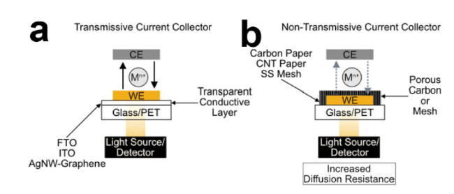
3.2 Research methods for photo-assisted lithium-sulfur batteries

4 Conclusion and outlook

Cite this article

Jia-Cheng Yu , Hao Su , Jun Zhang , Gang Xie , Ming Yao , Jin Qu . The Photo-Assisted Strategy for High Performance Lithium-Sulfur Batteries[J]. Progress in Chemistry, 2025 , 37(4) : 467 -478 . DOI: 10.7536/PC240726

1 Introduction

With the rapid development of industry, fossil fuels are being consumed rapidly and continuously causing environmental pollution. People have begun to turn to the use of green, renewable new energy sources. In order to fundamentally eliminate reliance on fossil fuels, the development, utilization, and storage of solar energy have become a global research focus. Since the 20th century, significant progress and achievements have been made in both secondary batteries and solar cells. However, integrating secondary batteries with photovoltaic cells remains a huge challenge[1-3].
Recently, lithium sulfur batteries (LSBs) have regained attention due to their high theoretical specific capacity (1675 mAh·g-1), high theoretical energy density (2600 Wh·kg-1), low cost, and environmental friendliness, and are expected to become a new system capable of replacing lithium-ion batteries[4-5]. To achieve solar energy utilization and large-scale storage, researchers have begun incorporating solar energy into lithium sulfur batteries. Wang et al.[6] integrated flexible thin-film solar cells with a rGO-coated lithium metal modified lithium sulfur battery to fabricate a bendable photoelectrochemical energy storage system, solving the problem of unstable output voltage from direct solar photovoltaic devices and achieving solar energy storage. Li et al.[7] connected an all-inorganic CsPbI2Br perovskite solar panel module with an all-solid-state lithium sulfur battery in series, creating an all-solid-state photo-rechargeable battery system for indoor energy harvesting and storage, thereby enabling safe utilization of indoor light energy by lithium sulfur batteries. Chen et al.[8] proposed a monolithic electrode configuration combining solid-state perovskite solar cells with high-performance lithium sulfur batteries, improving the integration level of solar-powered lithium sulfur batteries, and achieving excellent photoelectric conversion efficiency and reversible capacity.
Although lithium-sulfur batteries have broad application prospects, there are still many problems at present, such as: (1) the large density difference between the lithiated product Li2S and S8, which leads to significant volume expansion of the cathode material (80%), causing electrode structure pulverization and shedding, resulting in loss of active materials; (2) poor electronic conductivity of S8 and its lithiated products Li2S2/Li2S, leading to slow reactions during liquid-solid transitions and low utilization of active materials; (3) soluble lithium polysulfides Li2Sn (4≤n≤8) intermediates generated during the reaction, which can diffuse through the separator to the lithium anode side, namely the "shuttle effect," causing loss of active materials. At the lithium metal surface, Li2Sn gains/loses electrons, generating insulating S8/Li2S, which passivates the lithium metal anode, thereby blocking electron and ion conduction and causing rapid battery capacity decay; (4) sluggish kinetics of lithium polysulfide (LiPS) conversion prolongs their existence time, aggravating the "shuttle effect"; (5) uneven deposition of Li+ at the lithium anode causes severe dendrite growth, posing a risk of penetrating the separator and causing battery short circuits[9-10]. To address these issues, researchers have developed various electrocatalytic materials that utilize confinement, adsorption, and catalysis to promote the sulfur reduction reaction (SRR) during discharge and the sulfur evolution reaction (SER) during charging. This approach effectively facilitates complete sulfur reactions, suppresses the LiPS shuttle effect, enhances battery capacity, rate performance, and has become the mainstream strategy for improving lithium-sulfur batteries[11-19].
Similarly, introducing photocatalytic materials at the cathode to utilize the photocatalytic effect to promote the SRR and SER processes has become an emerging strategy for improving lithium-sulfur batteries[20]. This strategy not only reduces the reaction energy barriers of sulfur species conversion, thereby enhancing the performance of lithium-sulfur batteries thermodynamically, but also accelerates ion diffusion and sulfur species deposition, improving electrochemical reaction kinetics. Additionally, such batteries can convert light energy into chemical energy like solar cells, storing it and releasing it when needed, namely photocharging[21]. Recently, several researchers have adopted this strategy and achieved excellent performance. So far, no relevant reviews have comprehensively summarized the configurations and performances of light-assisted lithium-sulfur batteries, systematically introduced their mechanisms and design principles, or discussed future development prospects and improvement directions of light-assisted lithium-sulfur batteries.
In this review, we first introduce the working mechanism of photo-assisted lithium-sulfur batteries and propose design strategies; subsequently, from a material perspective, we review the typical configurations and recent examples of photo-assisted lithium-sulfur batteries; finally, based on current research progress, we summarize the current work and discuss future challenges and prospects for photo-assisted lithium-sulfur batteries.

2 Working Mechanism and Design Strategies of Light-Assisted Lithium-Sulfur Batteries

In this section, the photoelectrochemical mechanism of light-assisted lithium-sulfur batteries is first introduced in detail, and corresponding design strategies are proposed based on the mechanism.

2.1 Photoelectrochemical Principles of Light-Assisted Lithium-Sulfur Batteries

2.1.1 Fundamentals of Photochemistry

As early as 1972, Fujishima and Honda[22] successfully achieved water splitting using TiO2 photocatalysis. With continuous research, the solid-state photochemical mechanism has gradually been explored and understood. Taking semiconductor materials as an example, when they absorb external energy (such as light or thermal energy) exceeding the energy gap between the valence band and the conduction band, electrons in the valence band can be excited to jump into the conduction band, leaving behind electron holes in their original positions. Subsequently, two processes may occur: (1) electrons in the conduction band return to the electron holes in the valence band, releasing the energy difference in the form of heat or light; (2) photogenerated electrons and holes migrate to the material surface, driving redox reactions of external substances. Among these, the first process is dominant, while only a small fraction of photogenerated charge carriers can be captured by external substances.
According to these principles, researchers have designed numerous photothermal and photocatalytic materials with excellent performance, achieving solar-driven water evaporation[23-24], tumor therapy[25], pollutant degradation[26-28], water splitting[29-30], and CO2 reduction[31-32]. Similarly, researchers have applied this principle to battery systems, designing photo-assisted Li-ion batteries[33-34], Zn-ion batteries[35-36], Li-O2 batteries[37-39], Li-CO2 batteries[40-41], and Zn-O2 batteries[42-43], thereby enhancing the batteries' coulombic efficiency and capacity while reducing polarization voltage. Meanwhile, photo-assisted Li-S batteries have also been developed[44].

2.1.2 Photonic-Assisted Mechanism of Lithium-Sulfur Batteries

As is well known, unlike typical "rocking chair" batteries such as conventional Li-ion batteries, the Li-S electrochemical reaction in ether-based electrolytes involves the cathode S8 continuously accepting electrons and being lithiated into liquid LiPS during discharge, eventually reducing to solid Li2S. The charging process involves the delithiation and oxidation of Li2S back to S8. The deposition reaction equations for S8 and Li2S are as follows:

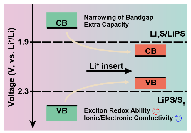
S8 + 2Li+ + 2e- ↔ Li2S8 E0 = 2.3 V

Li2S4 + 6Li+ + 6e- ↔ 4Li2S E0 = 1.9 V

according to the principle of photocatalytic technology, the structure and working mechanism diagram of the designed photo-assisted lithium-sulfur battery are shown in Figure 1. Under illumination, electrons in the valence band of the semiconductor catalyst at the cathode transition to the conduction band, leaving holes in their original positions. During discharge, the photogenerated electrons at the conduction band migrate to the material surface to drive the reduction lithiation reaction of sulfur species, while lithium metal at the anode is stripped, losing electrons and oxidized into Li+; during charging, driven by an external electric field, the photogenerated holes in the valence band can capture electrons from sulfur species and accelerate the oxidation delithiation reaction, whereas Li+ gains electrons and is reduced to lithium, depositing on the lithium metal anode.
图1 光辅助锂硫电池的(a)扣式电池组装结构图及(b)工作机理示意图

Fig.1 (a) Structural diagram of button type battery pack and (b) schematic diagram of working mechanism of photo-assisted lithium-sulfur battery

According to the aforementioned principle, researchers have developed two functions: light-charging and light-enhancement. From the perspective of catalytic mechanisms, for light-charging, its principle does not differ from other photocatalytic processes; the photogenerated holes on the photocatalyst directly oxidize sulfur species, achieving direct conversion of light energy into chemical energy, known as light-charging. However, for light-enhancement, due to the presence of an external electric field, its mechanism involves not only the driving of photogenerated charge carriers for sulfur species transformation but also a complex photoelectrochemical coupling process. This mode can enhance the catalytic and adsorption capabilities of the catalyst, improve electrochemical reaction kinetics, and reduce the energy barrier for sulfur species conversion, thereby further enhancing the electrochemical performance of the battery.

2.2 Design Strategies for Light-Assisted Lithium-Sulfur Batteries

2.2.1 Design Strategies of Photocatalysts

The performance of the photocatalyst directly affects the overall performance of the photo-assisted lithium-sulfur battery. An excellent photocatalyst can improve the electrochemical performance of lithium-sulfur batteries through various mechanisms such as photoelectrocatalysis, adsorption, and confinement effects. In addition to requirements on the conductivity and adsorption capability of the catalyst, its structural characteristics necessary for exerting photocatalytic effects should also be considered.
Since the light-assisted lithium-sulfur battery is designed based on the principle of photocatalysis, many design methods for photocatalytic materials can also be referenced. However, unlike other photocatalytic reactions, the reaction substrates in light-assisted lithium-sulfur batteries are sulfur species; therefore, the photocatalytic materials used should exhibit strong adsorption affinity towards sulfur species to enhance their catalytic capability within the lithium-sulfur battery. Moreover, in lithium-sulfur batteries, the photocatalyst also participates in the electrocatalytic reaction process. Hence, higher electronic and ionic conductivity of the material, as well as the electrochemical stability of the photocatalyst, are also of significant importance.
To ensure sufficient redox capability of photogenerated charge carriers from semiconductor photocatalysts for the Li-S reaction, the top energy level of the valence band should be lower than the highest reaction electromotive force of the Li-S reaction, which is 2.3 V (vs Li+/Li), and the bottom energy level of the conduction band should be higher than the highest electromotive force of the Li-S reaction, which is 1.9 V (vs Li+/Li). After meeting the above conditions, the following two strategies can be adopted to enhance the performance of semiconductor photocatalysts: (1) The bandgap of the semiconductor photocatalyst should be as narrow as possible to utilize longer wavelength light and improve its electrical conductivity; (2) Due to the extremely short lifetime of photogenerated charge carriers in semiconductor catalysts, which makes it difficult for them to diffuse to the material surface and be captured by external substances, constructing heterojunctions to form built-in electric fields can effectively separate photogenerated electrons and holes, thereby improving quantum efficiency[45-46]. Additionally, other external fields (such as magnetic fields[47-48], mechanical fields[49], acoustic fields[50], etc.) can also be introduced to accelerate charge transfer and separation.
In addition to the design requirements for the photocatalyst and the band structure of the heterojunction, it is also necessary to consider whether the crystal structure of the photocatalyst itself remains stable within the electrochemical reaction window of lithium-sulfur batteries, and whether it may lead to additional electrochemical side reactions, such as lithium storage. Due to the Burstein-Moss effect, when the doping level of a semiconductor material increases, its bandgap can change; the unoccupied energy states at the top of the valence band and in the conduction band separate, potentially causing a blue or red shift in the bandgap. Alternatively, if the number of inserted ions exceeds the degeneracy limit of the semiconductor, the bandgap may disappear completely[51-52]. As shown in Figure 2, this suggests that doping-induced lithiation of catalytic materials may create improved ion transport channels and enhanced electronic conductivity, thereby improving lithium-ion transport kinetics[53]. At the same time, bandgap narrowing may cause the generated excitons to lose sufficient redox capability to directly drive sulfur species conversion, weakening the photo-assisted effect. Moreover, the additional capacity contributed by side reactions complicates the evaluation of the beneficial effects introduced by the catalysts in Li-S reactions.
图2 锂离子嵌入改变半导体能带结构示意图

Fig.2 Schematic diagram of Li+ inserting changing semiconductor band structure

2.2.2 Design Strategies for Light Positive Electrodes

Since the photo-assisted battery requires irradiation to be introduced in situ during the electrochemical reaction process of the battery, and because photocatalysis is an interfacial reaction where photogenerated charge carriers have extremely short lifetimes, capable of driving only redox reactions of substances on the semiconductor surface, it demands that the photocatalyst at the positive electrode can efficiently absorb irradiation while also exhibiting good wettability with the electrolyte.
According to this requirement, as shown in Fig. 3, optically transparent current collectors can be divided into two types: transmissive and non-transmissive current collectors[54]. Transmissive current collectors typically use transparent conductive materials coated with conductive oxides such as fluorine-doped tin oxide (FTO) or indium-doped tin oxide (ITO), which generally exhibit high transmittance to sunlight. During battery assembly, the active material layer directly contacts the electrolyte membrane, allowing sunlight to pass through the substrate and irradiate onto the active material layer. Non-transmissive current collectors commonly employ porous conductive materials such as carbon paper or metallic foams, which typically offer excellent electrical conductivity and porosity. During battery assembly, the active material side is positioned beneath an optical window, enabling the electrolyte to infiltrate the electrode through the pores of the conductive substrate.
图3 (a)透过式以及(b)非透过式集流体的工作机理示意图[54]

Fig. 3 Schematic diagram of the working mechanism of (a) transmissive and (b) non-transmissive current collector[54]

However, at present, both transparent and non-transparent current collectors have certain drawbacks. Since transparent current collectors rely on conductive oxides to achieve good electrical conductivity, their deposition thickness needs to be increased, which is detrimental to transmittance. For non-transparent current collectors, if the active material faces away from the electrolyte, the electrolyte must diffuse through the porous electrode, which may lead to significant diffusion resistance. On the other hand, if the active material faces away from the optical window, light must pass through via holes in the current collector to reach the active material, resulting in a reduction of the actual irradiated area.
In addition to the selection of photoelectrode current collectors, the loading method of photocatalysts also plays a crucial role. Based on current research on photoassisted batteries, photocatalyst loading methods can be categorized into two types: in situ and ex situ approaches. The in situ method refers to directly growing photocatalysts on the current collector using techniques such as solvothermal synthesis, calcination, or vapor deposition, or constructing conductive three-dimensional current collectors loaded with photocatalysts via methods like electrospinning. Photoanodes fabricated through this approach typically offer advantages including uniform catalyst loading, large specific surface area, and high catalyst loading capacity. In contrast, the ex situ method primarily involves preparing a slurry by mixing photocatalysts with conductive carbon materials, conductive binders, and other substances, which is then directly coated onto the current collector via spraying, doctor-blading, or similar techniques to construct the photoanode. This method allows for more precise design of the crystal structure and assembled morphology of the photocatalysts, while the incorporation of conductive carbon materials can further enhance the electrical conductivity of the material.
The loading method of different photocatalysts also determines the loading method of active sulfur species. For photoanodes constructed via in situ methods, sulfur can generally be loaded by dropping an electrolyte solution of LiPS or a sulfur-containing slurry, and this method allows precise control over the amount of sulfur species loaded through the volume of the droplets. For photoanodes constructed via ex situ methods, besides the drop-loading approach, the classical melt-diffusion method can also be employed to directly load sulfur onto the catalyst, which is then coated onto the current collector to fabricate a photoanode loaded with both sulfur and the photocatalyst. The active species loaded via this method often exhibit stronger binding interactions with the catalyst.

2.2.3 Design Strategies for Optical Windows and Encapsulation Materials

To introduce external light into a sealed battery, the most common method is to design an optical window within the battery. For the optical window, on one hand, it is required that light can pass through with minimal loss; on the other hand, it must provide sufficient airtightness to prevent air ingress and electrolyte evaporation.
Reported studies on light-assisted batteries and in situ spectroscopic testing have already achieved this functionality with several high-performance commercial in situ batteries[55-57]. Taking coin cells as an example, researchers typically drill holes (usually with diameters of 5-12 mm) in the battery casing and use transparent materials along with adhesives to seal the window. Common sealing materials include quartz glass and PET films, while frequently used adhesives are epoxy resin glue, UV-curable glue, or directly using PET tape to seal the optical window. However, currently common sealing materials exhibit limited transmittance in the ultraviolet range below 400 nm, making it difficult to effectively utilize high-energy ultraviolet light; therefore, sealing materials with higher transmittance still need to be developed.
Here, several design directions for encapsulation materials and adhesives are proposed: encapsulation materials should transmit light across as many wavelength ranges as possible, especially short wavelengths; adhesives should exhibit solvent resistance to prevent dissolution by the electrolyte; the overall encapsulation material and adhesive should possess certain mechanical strength to prevent the encapsulation material from peeling off due to increased internal pressure caused by electrolyte volatilization over prolonged exposure to light; the adhesive and encapsulation material should have similar refractive indices and form a favorable interface to avoid Fresnel reflection, which could reduce light transmittance.

3 Typical Configurations and Research Methods of Light-Assisted Lithium-Sulfur Batteries

In this section, the research achievements of photo-assisted lithium-sulfur batteries in the past will be reviewed from two aspects: the typical configuration of the photoanode and the research methods.

3.1 Typical Configuration of the Light Positive Electrode

The configuration of the photo-positive electrode is the most critical factor in determining the performance of photo-assisted lithium-sulfur batteries. In previous studies, researchers have constructed photo-positive electrodes by loading photocatalysts onto non-transparent three-dimensional current collectors through methods such as in situ growth and slurry coating.
Liu et al.[58] in situ constructed a Co3O4/TiO2 photocatalytic p-n junction on carbon cloth through hydrothermal and calcination methods. This heterojunction can utilize the built-in electric field to achieve effective separation of photogenerated carriers and directional migration of soluble polysulfides, which is beneficial for further enhancing battery capacity. As shown in Fig. 4a, the carbon fibers in the carbon cloth have a diameter of approximately 10 μm, with TiO2 nanorods and Co3O4 nanosheets uniformly interwoven on the carbon fibers. This layered structure increases the specific surface area of the electrode, which is conducive to improving light absorption capability and exposing more catalytic sites. Yi et al.[59] constructed a Bi/Bi2O3/TiO2 heterojunction on carbon cloth using a similar method; the introduction of Bi2O3 forms a heterojunction with TiO2, enhancing photocatalytic performance, while the incorporation of metallic Bi with semiconductor characteristics induces a plasmonic resonance effect, further improving performance. As shown in Fig. 4b, elongated and well-aligned TiO2 structures exist on the surface of the carbon fibers, and the Bi/Bi2O3 effectively coats the surface of the TiO2 nanorods without significantly altering the overall morphology. Zhang et al.[60] utilized electrospinning and calcination techniques to in situ construct a TiO2-x@Ni-CNF electrode. As shown in Fig. 4c, bark-like amorphous TiO2-x is coated on the carbon nanofibers, while Ni nanoparticles are uniformly dispersed on the surface of the carbon nanofibers with an average diameter of approximately 10 nm.
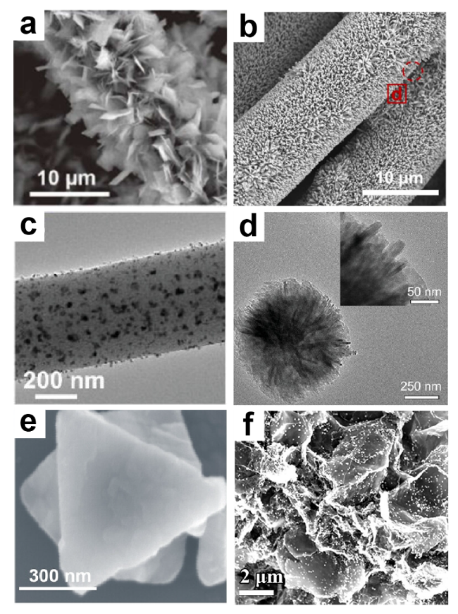
图4 (a)Co3O4/TiO2/CC的SEM图像,(b)Bi/Bi2O3/TiO2/CC的SEM图像,(c)NTCNF的TEM图像,(d)Ti-BPDC-d的TEM图像,(e)PHK的SEM图像,(f)rGO/CdS的TEM图像[58-63]

Fig.4 (a) SEM images of Co3O4/TiO2/CC. (b) SEM images of Bi/Bi2O3/TiO2/CC. (c) TEM images of NTCNF. (d) TEM images of Ti-BPDC-d. (e) SEM images of PHK. (f) TEM images of rGO/CdS[58-63].Copyright 2024,Elsevier,Copyright 2024,Wiley

In addition to in-situ construction of photoanodes loaded with photocatalysts, researchers have also employed ex-situ methods such as slurry coating to fabricate photoanodes. Wu et al.[61] synthesized Ti-BPDC using H2BPDC and tetraethyl titanate precursors through a solvothermal method, and subsequently introduced ligand defects via calcination, exposing numerous Ti-O clusters, and applied this MOF material as a photocatalyst in a light-assisted lithium-sulfur battery. As shown in Fig. 4d, Ti-BPDC-d forms a 3D nanostructured assembly from two-dimensional thin sheets, measuring 1-3 μm in size. The aggregated petal-like morphology increases the specific surface area of the material, facilitating light absorption and electron transfer. Liu et al.[62] designed a PHK heterojunction photocatalyst composed of HKUST-1 and perovskite through room-temperature self-assembly and sequential deposition methods. As shown in Fig. 4e, PHK retains the octahedral shape of HKUST-1 with an average particle size of approximately 600 nm, on whose surface quantum dots corresponding to Cs4PbBr6 and CsPbBr3 perovskites are uniformly deposited, exhibiting highly uniform size distribution. Yang et al.[63] designed and synthesized rGO/CdS composite materials for sulfur hosts and photocatalysts using a hydrothermal method. The introduction of rGO not only facilitates the separation of photogenerated carriers in CdS but also benefits sulfur loading due to its inherent two-dimensional planar structure. As shown in Fig. 4f, CdS can selectively nucleate and grow on rGO nanosheets anchored with Cd2+.
Researchers assembled photo-assisted lithium-sulfur batteries using these photocathodes and achieved excellent electrochemical performance. Table 1 summarizes the battery cycling performance and photocharging efficiency from previous studies on photo-assisted lithium-sulfur batteries.
表1 不同光辅助锂硫电池的研究工作总结

Table 1 Summary of the research operation of different photo-assisted lithium sulfur batteries

Photocatalyst S loading
(mg·cm-2
Illumination power density (mW·cm-2 Current density Initial specific capacity (mAh·g-1 Cycle Photo charging efficiency (%) Ref
CdS-TiO2 1 50 0.2 mA·cm-2 1500 50 2.58 44
Bi/Bi2O3/TiO2 9.236 60 0.2 mA·cm-2 1484 900 2.3 59
rGO/CdS 1.4 50 0.5 C 1137 100 7.7 63
PHK 1 50 5 C 679 1500 0.238 62
Co3O-TiO2 1 50 2 C 1087 200 0.4 58
Ti-BPDC-d 1.0~1.5 30 0.2 C 1239 150 - 61
Au@N-TiO2 1 60 3 C 982 50 0.99 64

3.2 Research Methods for Light-Assisted Lithium-Sulfur Batteries

3.2.1 Optical Properties of Photocatalysts

The optical properties and adsorption performance of photocatalysts are crucial for the overall electrochemical performance of photo-assisted lithium-sulfur batteries.
In order to analyze the band structure of photocatalysts, ultraviolet-visible absorption spectroscopy is commonly employed to assess their light absorption capabilities across various wavelength ranges. Subsequently, the bandgap of the material can be calculated using the Tauc plot method. Additionally, techniques such as X-ray photoelectron spectroscopy (XPS) valence band spectra, ultraviolet photoelectron spectroscopy (UPS), and Mott-Schottky analysis can be utilized to specifically determine the positions of the conduction band, valence band, and Fermi level, thereby enabling the evaluation of the redox capabilities of photogenerated carriers. Besides the band structure, carrier lifetime can also be investigated through photoluminescence (PL) spectroscopy[43,65].
In practical applications, constructing heterojunctions is often employed to enhance photocatalytic performance by utilizing the built-in electric field to separate photogenerated electrons and holes, thereby improving the lifetime of photogenerated carriers. Therefore, for heterojunction photocatalysts, studying their built-in electric fields and carrier transfer directions can better help understand the role of heterojunctions in photo-assisted lithium-sulfur battery systems. To investigate the direction of the built-in electric field, XPS spectroscopy is commonly used to determine the chemical shift of element characteristic peaks before and after material composites, thus further determining the photogenerated carrier transfer direction between heterojunctions[66-67]. In addition, researchers have also applied advanced in situ characterization techniques to analyze the built-in electric field and photogenerated carrier transfer pathways in heterojunctions. Liu et al.[58] conducted surface potential analysis using Kelvin probe force microscopy (KPFM) technology to intuitively verify the built-in electric field of the p-n junction. As shown in Figures 5a and 5b, TiO2 nanorods exhibit more positive surface potentials compared to Co3O4 nanosheets, indicating that the direction of the built-in electric field is from TiO2 to Co3O4. This built-in electric field enables photogenerated electrons and holes to migrate toward TiO2 and Co3O4, respectively, facilitating the separation of photogenerated carriers. Under illumination, even when TiO2 accumulates photogenerated electrons and Co3O4 accumulates photogenerated holes, the direction and strength of the built-in electric field remain unchanged, continuously achieving spatial separation of photogenerated carriers. Zhang et al.[60] analyzed the transfer pathway of photogenerated carriers using in situ irradiation X-ray photoelectron spectroscopy. As shown in Figures 5c and 5d, the Ti 2p orbitals of NTCNF shift toward higher binding energy under ultraviolet light irradiation. In contrast, the Ni 2p orbitals of NTCNF shift toward lower binding energy. This change in binding energy indicates that under UV irradiation, the electron density of the Ti 2p energy level decreases, while the electron density of the Ni 2p energy level increases, confirming that photogenerated electrons on the conduction band of amorphous TiO2-x@Ni heterojunction are transferred to the surface of Ni nanoparticles. Similarly, the decrease in binding energy of O 1s orbitals under illumination also suggests that some photogenerated electrons are captured by oxygen vacancies in amorphous TiO2-x, effectively enhancing the separation efficiency of photogenerated carriers.
图5 (a)黑暗条件下以及(b)光照条件下的Co3O4/TiO2的KPFM图像;NTCNF在有无辐照下的原位XPS的(c)Ti 2p以及(d)Ni 2p上的谱图[58,60]

Fig.5 (a) KPFM images of Co3O4/TiO2 under dark conditions and (b) under light conditions,and in situ XPS spectra of NTCNF with and without irradiation on (c) Ti 2p and (d) Ni 2p[58,60].Copyright 2024,Elsevier

3.2.2 Adsorption Properties of Photocatalysts

The adsorption capacity of catalysts for sulfur species is an important indicator for evaluating catalytic performance. Researchers usually employ visual adsorption experiments to investigate the adsorption properties of catalysts[11-12,68]. Wen et al.[69] immersed different catalysts in an electrolyte containing Li2S4 for 6 h; the electrolyte containing the catalyst exhibited a significantly lighter color, and ultraviolet-visible absorption spectroscopy further confirmed that Co/CoSe possesses a stronger adsorption capacity.
To investigate the influence of light on the experimental results, Yang et al.[63] designed different control experiments to decouple the effects of photocatalysis, photothermal effects, adsorption, and light itself. As shown in Fig. 6a, b, under different conditions, the color of the Li2S6 electrolyte changed to varying degrees. When the LiPS solution containing the catalyst was shielded with tin foil, no significant change occurred in the color or UV-Vis absorption spectrum of the electrolyte, indicating that the photoexcited photogenerated carriers played a decisive role in the adsorption behavior. After adsorption, XPS was further used to analyze the changes in the catalyst. As presented in Fig. 6c, under dark and light conditions, the S 2p spectra of rGO/CdS exhibited notable differences. Under illumination, the peak areas of terminal sulfur (ST) and bridging sulfur (SB) significantly increased, suggesting that polysulfides can be effectively anchored onto rGO/CdS after photocatalytic testing.
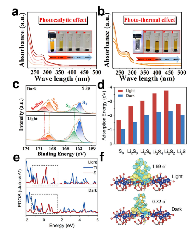
图6 (a)光催化效应以及(b)光热效应下的rGO/CdS的可视化吸附实验及其UV-Vis谱图;(c)rGO/CdS吸附后的XPS S 2p谱图;(d)Ti-BPDC-d在黑暗以及光照条件对硫物种的吸附能;(e)Ti-BPDC-d与Li2S6相互作用后的投影态密度以及(f)Li2S6与Ti-BPDC-d 在光照和黑暗条件下相互作用的电荷密度差图[61,63]

Fig.6 (a) Visualization adsorption experiments and UV-Vis spectra of rGO/CdS under photocatalytic effect and (b) photothermal effect. (c) XPS S 2p spectra of rGO/CdS after adsorption. (d) Adsorption energy of Ti-BPDC-d for sulfur species under dark and light conditions. (e) Projected density of states after interaction between Ti-BPDC-d and Li2S6,and (f) charge density difference between Li2S6 and Ti BPDC-d under light and dark conditions[61,63]. Copyright 2024,Elsevier,Copyright 2024,Wiley

In addition, theoretical simulations based on density functional theory (DFT) calculations can also be employed to analyze the adsorption behavior between photocatalysts and LiPSs. Wu et al.[61] simulated the adsorption configurations of Ti-BPDC-d with sulfur species under different lithiation states, finding that Ti-BPDC-d in the excited state exhibits higher binding energy toward sulfur species (Fig. 6d). By examining the distribution of different charge densities (DCD) (Fig. 6f), an increase in density near Ti and O atoms and a decrease near S and Li atoms were observed, indicating stronger Lewis acid-base interactions between Ti-BPDC-d and Li2S6 under light irradiation. The projected density of states (PDOS) after interaction between Ti-BPDC-d and Li2S6 shown in Fig. 6e reveals that the PDOS of Ti-BPDC-d after adsorbing Li2S6 under light irradiation displays greater overlap, suggesting stronger orbital hybridization between Ti 3d and S 3p compared to dark conditions, further accelerating electron transfer and enhancing bond strength, thereby improving catalytic performance. These results indicate that under light irradiation, the chemical interaction between Ti-BPDC-d and Li2S6 becomes stronger, leading to faster LiPSs conversion.

3.2.3 Photonic-Assisted Enhancement of Kinetics in Lithium-Sulfur Batteries

The introduction of light is also beneficial for improving the electrochemical reaction kinetics of lithium-sulfur batteries due to photocatalysis and the photoconductive effect. As shown in Figures 7a~c, the relationship between the peak current in cyclic voltammetry (CV) and the square root of the scan rate, as well as the electrochemical impedance spectroscopy (EIS) spectra of the lithium-sulfur battery under illumination, indicate that the introduction of light can enhance the electron and Li+ transport kinetics. The Tafel curves corresponding to Li2S deposition also demonstrate that illumination improves the kinetic transformation of sulfur species[44].
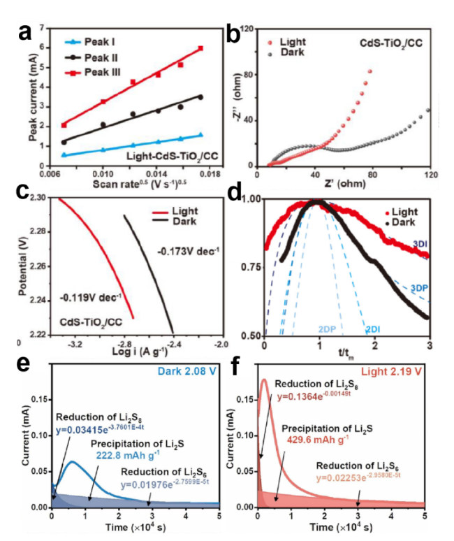
图7 CdS-TiO2/CC 电池有光照和无光照的(a)CV峰值电流与扫描速率平方根的关系图;(b)EIS谱和(c)Tafel曲线;(d)CdS-TiO2/CC 电池在光照和无光照情况下Li2S成核过程的无量纲电流-时间瞬态图;Bi/Bi2O3/TiO2电池(e)光照下和(f)无光照下的恒电位放电曲线[44,59]

Fig.7 (a) Relationship between CV peak current and square root of scan rate for CdS-TiO2/CC cells under illumination and non-illumination. (b) EIS spectrum and (c) Tafel curve. (d) Non dimensional current time transient of Li2S nucleation process in CdS-TiO2/CC cells under illumination and non-illumination,and constant potential discharge curves for Bi/Bi2O3/TiO2 cells under illumination and non-illumination[44,59],Copyright 2022,2024,Elsevier

In addition, researchers have conducted an in-depth investigation into the role of light-assisted improvement on Li2S deposition kinetics. Under illumination, Li2S exhibits higher nucleation capacity and shorter nucleation time. The dimensionless current-time transient plots also reveal that the deposition mode of Li2S under illumination transitions from 3D progressive to 3D instantaneous nucleation (Figure 7d~f).
Yi et al.[59] utilized an in situ optical setup to monitor the deposition process of Li2S at the electrode. As seen in the in situ optical micrographs from Fig. 8a, b, under dark conditions, noticeable insoluble deposits appeared on the electrode surface after 45 min and rapidly grew to a thickness of 200 μm within 100 min; however, under light exposure, the electrode remained in its initial state without significant changes.
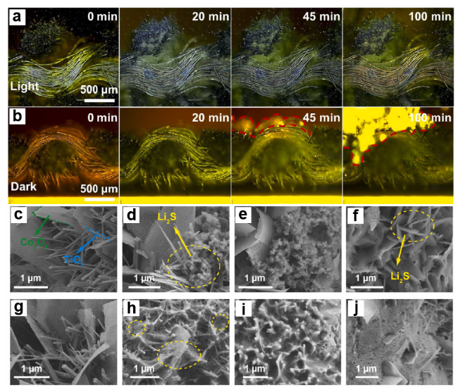
图8 Bi/Bi2O3/TiO2 光正极在(a)光照下和(b)无光照下的放电过程的原位光学显微相片,Co3O4/TiO2/CC电池在(c~f)光照下以及(g~j)无光照下的Li2S沉积过程的SEM图像[58-59]

Fig. 8 In situ optical micrographs of the discharge process of Bi/Bi2O3/TiO2 photocathode under (a) illumination and (b) non illumination,and SEM images of the Li2S deposition process of Co3O4/TiO2/CC cells under (c~f) illumination and (g~j) no illumination[58-59],Copyright 2024,Elsevier

To investigate the effect of the synergistic interaction between the built-in electric field and the optical field on Li2S deposition, Liu et al.[58] observed the deposition morphology of Li2S on electrodes through ex situ SEM. As shown in Fig. 8c,g, regardless of light irradiation, both Co3O4 nanosheets and TiO2 nanorods exhibited clear and smooth surfaces at the initial stage of Li2S deposition. Under dark conditions, Li2S randomly deposited on the surfaces of TiO2 and Co3O4, forming a spider-web-like structure (Fig. 8h). Subsequently, a colloidal film of Li2S formed between the Co3O4 nanosheets and TiO2 nanorods, making it difficult to clearly observe the morphologies of TiO2 and Co3O4 (Fig. 8i). This Li2S colloidal film may hinder further Li2S deposition, and the responsive current nearly disappeared. The Li2S deposits were rearranged, and the colloidal film of Li2S transformed into two-dimensional foam-like Li2S randomly adhering between Co3O4 and TiO2 (Fig. 8j). In contrast, during Li2S deposition under illumination, granular Li2S nanoparticles preferentially deposited at the base of TiO2 nanorods (Fig. 8d). Subsequently, these granular Li2S nanoparticles continued to deposit from the base and gradually grew upward along the TiO2 nanorods, exhibiting a three-dimensional progressive deposition feature (Fig. 8e). During prolonged deposition, the granular Li2S gradually transformed into plate-like Li2S precipitates that regularly grew on TiO2 (Fig. 8f). Notably, even after extended deposition, smooth Co3O4 nanosheets remained clearly observable. In dark conditions, the thin film formed by Li2S deposition almost covered all reactive sites, leading to a lack of accessible active sites for polysulfides, thereby preventing further deposition. In other words, the three-dimensional growth mode induced by light irradiation is beneficial for enhancing the deposition capability.

3.2.4 Photonic Assistance in Enhancing the Thermodynamics of Lithium-Sulfur Batteries

To investigate the improvement of photo-assisted effects on the thermodynamics of lithium-sulfur batteries, Liu et al.[62] measured EIS curves of photo-assisted lithium-sulfur batteries at various temperatures and voltages. According to the Arrhenius equation, they calculated corresponding slope values and ultimately determined the activation energies under different conditions. As shown in Figure 9a, based on the differences in activation energy of the PHK battery before and after illumination, it can be seen that light has minimal impact on the reaction tendency during the solid-liquid transition stage. However, for the solid-liquid transition, under the coupling of photocatalysis and electrocatalysis, the reaction activation energy decreased from 0.37 eV to -0.16 eV, indicating that photocatalysis can selectively reduce the energy barrier of the liquid-solid rate-controlling step during the SRR process, thereby promoting the sulfur conversion reaction thermodynamically.
图9 (a)PHK 电极在不同电压下的活化能以及(b)Ti-BPDC-d电池在光照与黑暗条件下S8转化为Li2S的吉布斯自由能[61-62]

Fig.9 (a) Activation energy of PHK electrode at different voltages and (b) Gibbs free energy of S8 conversion to Li2S in Ti-BPDC-d battery under light and dark conditions[61-62],Copyright 2024,Wiley

In addition, Wu et al.[61] determined the Gibbs free energy of the reduction pathway from S8 to Li2S species in lithium-sulfur batteries under both light and dark conditions through DFT calculations. The optimized models and free energy distribution of the polysulfide intermediates are shown in Figure 9b, where the lower Gibbs free energy at each step under illumination indicates that the sulfur reduction reaction is thermodynamically more favorable in this medium. The transformation from Li2S2 to Li2S, which involves the conversion between two insulating solid products with a theoretical capacity of approximately 836 mAh·g-1, is considered as the rate-limiting step of the SRR lithiation reduction process. This step exhibits a lower transition energy barrier (0.69 eV) under light irradiation, which facilitates improved sulfur conversion efficiency and practical utilization, thereby enhancing the performance of lithium-sulfur batteries.

3.2.5 Light-Assisted Enhancement of Photo-Charging Performance in Lithium-Sulfur Batteries

The photo-rechargeable lithium-sulfur battery with a photo-positive structure can not only utilize light energy to enhance battery performance under the drive of an external electric field, but also directly convert light energy into chemical energy and realize the utilization and storage of light energy without relying on the external electric field[21]. Taking the CdS-TiO2/CC cathode-based photobattery as an example[44], as shown in Figure 10a, after the battery is fully discharged, under illumination, the voltage of the CdS-TiO2/CC battery rapidly increases to about 2.1 V at the initial stage, then continues to slowly increase with prolonged illumination time, and finally reaches approximately 2.22 V after 10 h. During the subsequent discharge process under illumination, it delivers 608 mAh·g-1 with an overall photoelectric conversion efficiency of 2.3%, demonstrating excellent cycle reversibility during the photocharging process.
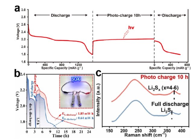
图10 (a)CdS-TiO2/CC电池与(b)rGO/CdS电池在没有任何外部电源的恒电流充放电图以及(c)完全放电和10小时光充电后的Raman光谱分析[44,59,63]

Fig.10 (a) Constant current charge and discharge electrocardiograms of CdS-TiO2/CC cells and (b) rGO/CdS cells without any external power source,and (c) Raman spectroscopy analysis after complete discharge and ten hours of photo charging[44,59,63] Copyright 2022,2024,Elsevier,Copyright 2024,Wiley

Yang et al.[63] investigated the actual contribution of light energy during the photo-charging process. As shown in Fig. 10b, due to inherent polarization effects within the battery, the battery voltage may slowly and continuously increase even after complete discharge. However, under illumination, the voltage rises more rapidly and delivers more energy during subsequent discharge, further indicating that the battery can absorb light energy and store it in the form of chemical energy. In addition, Yi et al.[59] explored the mechanism of photo-charging. As shown in Fig. 10c, by comparing Raman spectra of the electrode before and after illumination, the characteristic peak corresponding to Li2S exhibits a red shift after 10 h of light exposure, indicating that Li2S is oxidized into Li2Sx, further confirming that light energy is utilized and stored as chemical energy within this structure.

4 Conclusion and Prospect

Strategies to improve the intrinsic issues of lithium-sulfur batteries through the photo-induced effect have attracted increasing attention. This article introduces the mechanisms of photo-assisted lithium-sulfur batteries and discusses the design methods of photo-cathodes in such systems. It further elaborates on the fundamental understanding of how light enhances the photoelectrochemical processes of sulfur in Li-S batteries. The article reviews and summarizes recent advances in photo-assisted lithium-sulfur batteries from two perspectives: typical configurations and research methodologies.
The improvement in the adsorption and catalytic capabilities of photocatalysts and the enhanced performance of lithium-sulfur batteries caused by light irradiation have been confirmed by researchers. However, there are still many challenges limiting the further development of photo-assisted lithium-sulfur batteries. Herein, current issues are summarized, and potential strategies are proposed for reference: (1) The actual photoelectrochemical processes occurring during the operation of photo-assisted lithium-sulfur batteries are relatively complex. Limited by characterization techniques, understanding regarding the microscopic synergistic effects of light and electric fields on the photoelectrochemical/physical behavior of lithium-sulfur batteries, as well as the limitations of light charging steps, remains insufficient. Additionally, no researchers have yet quantified the photocatalytic efficiency during studies of the photo-assisted process in lithium-sulfur batteries, which is significant for further optimizing catalytic materials. This might require more advanced in situ characterization techniques or computational simulation methods to analyze the real battery working process. (2) The influence of different wavelengths of light on lithium-sulfur batteries remains unknown. Researchers could conduct more detailed investigations into this aspect and develop optical filters to eliminate harmful light sources, thus promoting further applications of photo-assisted lithium-sulfur batteries. (3) The cycling stability of photo-assisted lithium-sulfur batteries requires further breakthroughs. Light irradiation and photocatalytic effects may lead to reduced electrolyte stability due to decomposition and volatilization caused by photothermal effects. Moreover, long-term irradiation can cause structural collapse of photocatalysts, resulting in diminished catalytic performance, inevitably reducing the cycle life of photo-assisted lithium-sulfur batteries. Researchers could leverage the improved ion conductivity and elevated operating temperature brought by the photo-assisted mechanism to address the low ionic conductivity of gel/solid-state electrolytes and their poor performance at room temperature, thereby achieving complementary advantages and enhancing overall battery performance. (4) There is a lack of practical commercial application forms for the photo-assisted battery system. Currently, research on photo-assisted lithium-sulfur batteries remains limited, with different researchers adopting varying conditions (such as electrode and optical window configurations, area loading, light power density, etc.), lacking unified research methodologies and evaluation criteria. Furthermore, most existing studies remain at the laboratory-scale coin cell level; how to incorporate in situ light irradiation into pouch or cylindrical cells for specific application scenarios still needs to be explored.
As a novel energy device, light-assisted lithium-sulfur batteries offer a significant advantage over traditional solar cells due to their more integrated battery structure, which enables the direct absorption and conversion of light energy into chemical energy. Therefore, they can serve as a complementary solution to current photovoltaic power generation and energy storage stations by combining both functions into a single system, thereby reducing energy losses associated with power transmission. In addition, given the remarkable performance improvement of light-assisted lithium-sulfur batteries under illumination, they can also be utilized as energy storage devices in high-altitude cold regions. This approach leverages the high solar radiation resulting from the thin air in such areas to enhance the electrochemical performance and operating temperature of the batteries, addressing the challenges faced by energy storage devices in these regions.
We believe that through the joint efforts of researchers, the problems and challenges faced by light-assisted lithium-sulfur batteries will be effectively addressed, achieving a harmonious integration of light energy utilization and energy storage, thereby better meeting future energy demands.
[1]
Jiang Q, Zhu K. Nat. Rev. Mater., 2024, 9(6): 399.

[2]
Yu C, Zou Q J, Wang Q, Zhao Y, Ran X C, Dong G Q, Peng C W, Allen V, Cao X M, Zhou J, Zhao Y, Zhang X D. Nat. Energy, 2023, 8(10): 1119.

[3]
Han M C, Zhang J H, Yu C Y, Yu J C, Wang Y X, Jiang Z G, Yao M, Xie G, Yu Z Z, Qu J. Angew. Chem. Int. Ed., 2024, 63(22): e202403695.

[4]
Service R F. Science, 2018, 359: 1080.

[5]
Seh Z W, Sun Y M, Zhang Q F, Cui Y. Chem. Soc. Rev., 2016, 45(20): 5605.

[6]
Wang A X, Tang S, Kong D B, Liu S, Chiou K, Zhi L J, Huang J X, Xia Y Y, Luo J Y. Adv. Mater., 2018, 30(1): 1703891.

[7]
Li T T, Yang Y B, Zhao B S, Wu Y, Wu X W, Chen P, Gao X P. Chem. Eng. J., 2023, 455: 140684.

[8]
Chen P, Li G R, Li T T, Gao X P. Adv. Sci., 2019, 6: 1900620.

[9]
Zhou L, Danilov D L, Qiao F, Wang J F, Li H T, Eichel R A, Notten P H L. Adv. Energy Mater., 2022, 12(44): 2202094.

[10]
Liu H J, Yang C Y, Han M C, Yu C Y, Li X F, Yu Z Z, Qu J. Angew. Chem. Int. Ed., 2023, 62(11): e202217458.

[11]
Lu H B, Zeng Q H, Xu L L, Xiao Y B, Xie L, Yang J H, Rong J H, Weng J Q, Zheng C, Zhang Q, Huang S M. Angew. Chem. Int. Ed., 2024, 63(8): e202318859.

[12]
Lao Z J, Han Z Y, Ma J B, Zhang M T, Wu X R, Jia Y Y, Gao R H, Zhu Y F, Xiao X, Yu K, Zhou G M. Adv. Mater., 2024, 36(2): 2309024.

[13]
Wang X, Zhang X M, Zhao Y, Luo D, Shui L L, Li Y B, Ma G, Zhu Y J, Zhang Y G, Zhou G F, Yu A P, Chen Z W. Angew. Chem. Int. Ed., 2023, 62(42): e202306901.

[14]
Shen Z H, Jin X, Tian J M, Li M, Yuan Y F, Zhang S, Fang S S, Fan X, Xu W G, Lu H, Lu J, Zhang H G. Nat. Catal., 2022, 5(6): 555.

[15]
Lai C, Li G C, Ye S H, Gao X P. Prog. Chem., 2011, 23: 527.

(赖超, 李国春, 叶世海, 高学平. 化学进展, 2011, 23: 527.).

[16]
Li H, Meng R W, Ye C, Tadich A, Hua W X, Gu Q F, Johannessen B, Chen X, Davey K, Qiao S Z. Nat. Nanotechnol., 2024, 19(6): 792.

[17]
Liang Z W, Shen J D, Xu X J, Li F K, Liu J, Yuan B, Yu Y, Zhu M. Adv. Mater., 2022, 34(30): 2200102.

[18]
Liang Z W, Peng C, Shen J D, Yuan J J, Yang Y, Xue D F, Zhu M, Liu J. Small, 2024, 20(18): 2309717.

[19]
Shen J D, Liang Z W, Gu T T, Sun Z Y, Wu Y W, Liu X Q, Liu J H, Zhang X Y, Liu J W, Shen L, Zhu M, Liu J. Energy Environ. Sci., 2024, 17(16): 6034.

[20]
Li N, Wang Y R, Tang D M, Zhou H S. Angew. Chem. Int. Ed., 2015, 54(32): 9271.

[21]
Li J F, Ren C W, Zhang L B, Jiang W H, Liu H M, Su J, Li M. J. Energy Chem., 2022, 65: 205.

[22]
Fujishima A, Honda K. Nature, 1972, 238(5358): 37.

[23]
Jiao F Z, Wu J, Zhang T T, Pan R J, Wang Z H, Yu Z Z, Qu J. ACS Appl. Mater. Interfaces, 2023, 15(34): 41007.

[24]
Wu J, Zhang T T, Qu J, Jiao F Z, Hu C, Zhao H Y, Li X F, Yu Z Z. ACS Appl. Mater. Interfaces, 2023, 15(24): 29457.

[25]
Chen Q, Hu Q Y, Dukhovlinova E, Chen G J, Ahn S, Wang C, Ogunnaike E A, Ligler F S, Dotti G, Gu Z. Adv. Mater., 2019, 31(23): 1900192.

[26]
Pan R J, Wu J, Qu J, Zhang T T, Jiao F Z, Zhao M, Han M Y, Li X F, Yu Z Z. J. Mater. Sci. Technol., 2024, 179: 40.

[27]
Zhang T T, Qu J, Wu J, Jiao F Z, Li C J, Gao F L, Liu J, Yu Z Z, Li X F. Adv. Funct. Mater., 2024, 34(39): 2403505.

[28]
Zhou L, Abdelkrim Y, Jiang Z G, Yu Z Z, Qu J. Prog. Chem., 2022, 34(9): 1935.

(周丽, Yasmine Abdelkrim, 姜志国, 于中振, 曲晋. 化学进展, 2022, 34(9): 1935.).

[29]
Kang Y Y, Qi H Z, Wan G D, Zhen C, Xu X X, Yin L C, Wang L Z, Liu G, Cheng H M. Joule, 2022, 6(8): 1876.

[30]
Hisatomi T, Domen K. Nat. Sustain., 2024, 7(9): 1082.

[31]
Fu J W, Jiang K X, Qiu X Q, Yu J G, Liu M. Mater. Today, 2020, 32: 222.

[32]
Bie C B, Zhu B C, Xu F Y, Zhang L Y, Yu J G. Adv. Mater., 2019, 31(42): 1902868.

[33]
Paolella A, Faure C, Bertoni G, Marras S, Guerfi A, Darwiche A, Hovington P, Commarieu B, Wang Z R, Prato M, Colombo M, Monaco S, Zhu W, Feng Z M, Vijh A, George C, Demopoulos G P, Armand M, Zaghib K. Nat. Commun., 2017, 8: 14643.

[34]
Yu S W, Sun H L, Ullah Z, Chen L D, An X W, Chen M L, Zhu S P, Liu L W, Li Q. Adv. Funct. Mater., 2024, 34(39): 2403295.

[35]
Wang S C, Zhu C C, Ji J L, Li M Y, Zhao L, Cai F S, Tao Z L. Small Meth., 2024, 8(12): 2400557.

[36]
Zha W W, Ruan Q S, Ma L, Liu M, Lin H W, Sun L T, Sun Z M, Tao L. Angew. Chem. Int. Ed., 2024, 63(15): e202400621.

[37]
Wen B, Huang Y H, Jiang Z L, Wang Y Z, Hua W B, Indris S, Li F J. Adv. Mater., 2024, 36(32): 2405440.

[38]
Yu H H, Liu D P, Fu Z R, Wang S, Zuo X T, Feng X L, Zhang Y. Angew. Chem. Int. Ed., 2024, 63: e202401272.

[39]
Wang X X, Guan D H, Miao C L, Kong D C, Zheng L J, Xu J J. J. Am. Chem. Soc., 2023, 145(10): 5718.

[40]
Guan D H, Wang X X, Li F, Zheng L J, Li M L, Wang H F, Xu J J. ACS Nano, 2022, 16(8): 12364.

[41]
Wang J H, Li S, Chen Y F, Dong L Z, Liu M, Shi J W, Li S L, Lan Y Q. Adv. Funct. Mater., 2022, 32: 2210259.

[42]
Liang S, Zheng L J, Song L N, Wang X X, Tu W B, Xu J J. Adv. Mater., 2024, 36: 2307790.

[43]
Fu X L, He F, Liu X, Ge B H, Zhang D Y, Chang Q, Gao J C, Li X D, Huang C S, Li Y L. Proc. Natl. Acad. Sci. U. S. A., 2024, 121(14): e2318777121.

[44]
Liu Y H, Qu J, Chang W, Yang C Y, Liu H J, Zhai X Z, Kang Y, Guo Y G, Yu Z Z. Energy Storage Mater., 2022, 50: 334.

[45]
Xu Q L, Zhang L Y, Cheng B, Fan J J, Yu J G. Chem, 2020, 6(7): 1543.

[46]
Kosco J, Gonzalez-Carrero S, Howells C T, Fei T, Dong Y F, Sougrat R, Harrison G T, Firdaus Y, Sheelamanthula R, Purushothaman B, Moruzzi F, Xu W D, Zhao L Y, Basu A, De Wolf S, Anthopoulos T D, Durrant J R, McCulloch I. Nat. Energy, 2022, 7(4): 340.

[47]
Yang D M, Sun G R, Wang X R, Li F Y, Gao Z, Zhang P L, Lu W, Feng M. Chem. Eng. J., 2023, 474: 145712.

[48]
Wang X X, Guan D H, Li F, Li M L, Zheng L J, Xu J J. Adv. Mater., 2022, 34: 2104792.

[49]
Tian S L, Song L N, Chang L M, Liu W Q, Wang H F, Xu J J. Nano Energy, 2024, 126: 109677.

[50]
Tian S L, Song L N, Chang L M, Liu W Q, Wang H F, Xu J J. Adv. Energy Mater., 2024, 14: 2303215.

[51]
Milot R L, Klug M T, Davies C L, Wang Z P, Kraus H, Snaith H J, Johnston M B, Herz L M. Adv. Mater., 2018, 30(44): 1804506.

[52]
Pujari A, Kim B M, Sayed F N, Sanders K, Dose W M, Mathieson A, Grey C P, Greenham N C, De Volder M. ACS Energy Lett., 2023, 8(11): 4625.

[53]
Nguyen V P, Qureshi Y, Shim H C, Yuk J M, Kim J H, Lee S M. Small Struct., 2024, 5(8): 2400196.

[54]
Pujari A, Kim B M, Greenham N C, De Volder M. Small Meth., 2024, 8(10): 2301572.

[55]
Zhai X Z, Qu J, Wang J, Chang W, Liu H J, Liu Y H, Yuan H F, Li X F, Yu Z Z. Energy Storage Mater., 2021, 42: 753.

[56]
Zhai X Z, Qu J, Hao S M, Jing Y Q, Chang W, Wang J, Li W, Abdelkrim Y, Yuan H F, Yu Z Z. Nano-Micro Lett., 2020, 12: 56.

[57]
Liu Y H, Chang W, Qu J, Sui Y Q, Abdelkrim Y, Liu H J, Zhai X Z, Guo Y G, Yu Z Z. Energy Storage Mater., 2022, 46: 313.

[58]
Liu Y H, Yang C Y, Yu C Y, Yu J C, Han M C, Zhang J H, Yu Y, Yu Z Z, Qu J. Next Energy, 2024, 4: 100134.

[59]
Yi S, Su Z, Chen H L, Zhao Z Q, Wang X W, Zhang Y Y, Niu B, Long D H. Appl. Catal. B Environ. Energy, 2024, 348: 123853.

[60]
Zhang P P, Zhao Y G, Li Y K, Li N, Silva S R P, Shao G S, Zhang P. Adv. Sci., 2023, 10: 2206786.

[61]
Wu J Y, Wang Y, Song L N, Wang Y F, Wang X X, Li J F, Xu J J. Adv. Funct. Mater., 2024, 34(41): 2404211.

[62]
Liu Y H, Wu F, Hu Z Q, Zhang F L, Wang K, Li L, Chen R J. Angew. Chem. Int. Ed., 2024, 63(25): e202402624.

[63]
Yang T Z, Mao H N, Zhang Q Q, Xu C, Gao Q Z, Cai X, Zhang S S, Fang Y P, Zhou X S, Peng F, Yang S Y. Angew. Chem. Int. Ed., 2024, 63(22): e202403022.

[64]
Zhao F, Yang K, Liu Y X, Li J, Li C, Xu X W, He Y B. Adv. Sci., 2024, 11(38): 2402978.

[65]
Luo X M, Jiao Y H, Li H, Liu Q, Liu J F, Wang M W, Liu Y. Materials, 2024, 17: 2190

[66]
Du D F, Zhu Z, Chan K Y, Li F J, Chen J. Chem. Soc. Rev., 2022, 51(6): 1846.

[67]
Zhang L Y, Zhang J J, Yu H G, Yu J G. Adv. Mater., 2022, 34: 2107668.

[68]
Ren X Y, Wang Q, Pu Y L, Sun Q, Sun W B, Lu L H. Adv. Mater., 2023, 35(44): 2304120.

[69]
Wen Y, Shen Z, Hui J F, Zhang H G, Zhu Q S. Adv. Energy Mater., 2023, 13: 2204345.

Outlines

/