Home Journals Progress in Chemistry
Progress in Chemistry

Abbreviation (ISO4): Prog Chem      Editor in chief: Jincai ZHAO

About  /  Aim & scope  /  Editorial board  /  Indexed  /  Contact  / 
Review

Structural Design and Applications in CO2 Conversion of Electrospun Nanofiber Catalyst

  • Guichu Yue , 1, * ,
  • Yaqiong Wang 2 ,
  • Jie Bai 1 ,
  • Yong Zhao 1, 2 ,
  • Zhimin Cui , 2, *
Expand
  • 1 College of Chemical Engineering,Inner Mongolia University of Technology,Hohhot 010051,China
  • 2 School of Chemistry,Beihang University,Beijing 100191,China
* (Zhimin Cui);
(Guichu Yue)

Received date: 2024-10-14

  Revised date: 2025-01-03

  Online published: 2025-03-20

Supported by

National Natural Science Foundation of China(52172080)

Basic Research Funds for University Directly under the Inner Mongolia Autonomous Region(JY20250034)

Research Initiation Fund of Inner Mongolia University of Technology(BS2025005)

MOE Key Laboratory of Resources and Environmental System Optimization,North China Electric Power University(KLRE-KF 202307)

Abstract

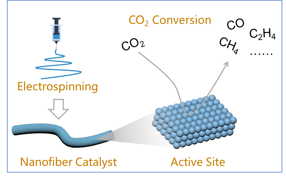
Using catalytic processes to convert CO2 into low-carbon fuels and fine chemicals is one of the most efficient paths to addressing global energy imbalance and CO2 excess emissions. The advantages of one-dimensional nanocatalysts in long-range electron transport and controllable internal structure endow them with widely utilization in catalysis. Electrospinning,a top-down method for fabrication of fibers,offers unique advantages in regulating fiber composition and structure. This paper systematically reviews the designing strategies and application advancements of fiber catalysts based on electrospinning,including fully controllable synthesis strategies for multilevel structured fibers,methods for introducing active sites via one-step and post-load techniques,and research case of fiber catalysts in CO2 conversion. This review provides valuable references for the development of new concepts,methods,processes,and applications of fiber catalysts for CO2 conversion.

Contents

1 Introduction

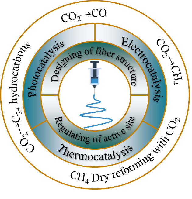
2 Electrospinning in designing of fiber catalysts
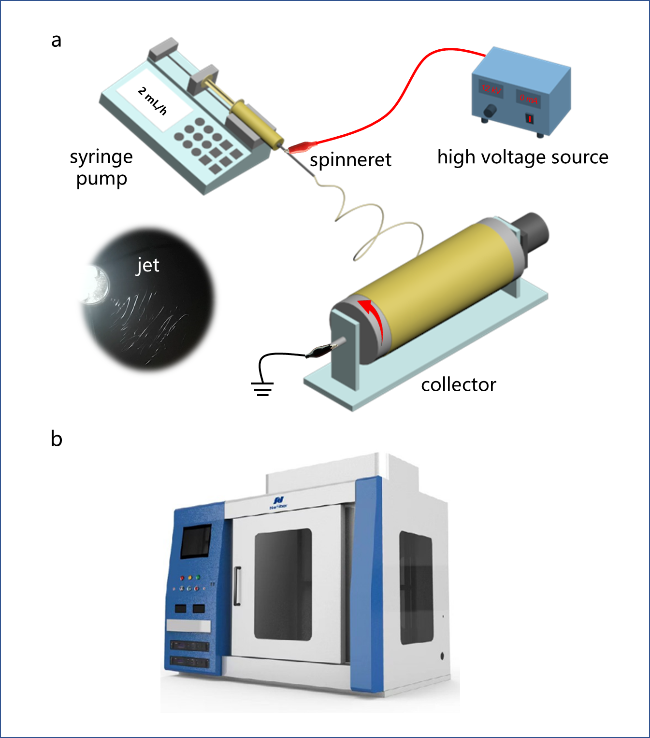
2.1 Electrospinning

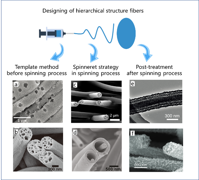
2.2 Designing of fiber structures

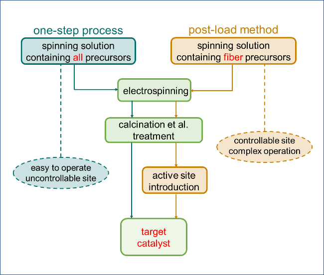
2.3 Introducing of active sites

3 Applications of fiber catalysts in CO2 conversion

3.1 Photocatalytic CO2 conversion

3.2 Electrocatalytic CO2 conversion

3.3 Thermocatalytic CO2 conversion

4 Conclusion and outlook

Cite this article

Guichu Yue , Yaqiong Wang , Jie Bai , Yong Zhao , Zhimin Cui . Structural Design and Applications in CO2 Conversion of Electrospun Nanofiber Catalyst[J]. Progress in Chemistry, 2025 , 37(4) : 508 -518 . DOI: 10.7536/PC241004

1 Introduction

Since the beginning of the Second Industrial Revolution, the continuously accelerating global industrial development has profoundly influenced human life and production. Modern chemical industry, power and other key industrial sectors heavily rely on the utilization of coal and petroleum, directly leading to a rapid increase in greenhouse gas CO2 emissions[1-4]. Consequently, climate and environmental issues have emerged globally, such as glacier melting, ocean acidification, and desertification[5]. In recent years, frequent occurrences of severe climate and environmental problems continually warn humanity that it must re-examine traditional energy structures and reduce its deep reliance on non-renewable resources[6]. At the same time, developing new physical and chemical technologies capable of directly utilizing atmospheric CO2 is becoming increasingly urgent. Recently, using CO2 as a raw material for producing low-carbon fuels and fine chemicals has attracted extensive attention from researchers[2]. Currently developed approaches for CO2 conversion and utilization include photocatalysis[7-8], electrocatalysis[9-10], and thermal catalysis[11-12], such as the process of artificial starch synthesis starting from CO2 pioneered by Chinese scientists, which has achieved true "technical creation"[13]. Heterogeneous catalysis plays a central role in modern chemical industries. The design of heterogeneous catalysts is an interdisciplinary research field involving synthetic chemistry, coordination chemistry, surface/interfacial chemistry, etc.[14-16]. Conducting fundamental and applied research on heterogeneous catalysts used for CO2 conversion remains a hotspot in the catalysis field.
Heterogeneous catalysts can be classified into zero-dimensional catalysts (e.g., SiO2 nanospheres as supports[17]), one-dimensional catalysts (e.g., TiO2 fibers as supports[18]), two-dimensional catalysts (e.g., graphene as support[19]), and three-dimensional catalysts (e.g., bulk molecular sieves as supports[20]), according to their morphological structures. Fiber catalysts offer not only advantages such as resistance to agglomeration, reduced powdering, and ease of separation, but also possess benefits including long-range electron transport pathways along the length direction, controllable openness of internal spatial structures, and anisotropy along the axial direction, making them widely applicable in the field of catalysis. Common synthesis methods for fiber catalysts include template methods[21], vapor phase growth methods[22], hydrothermal synthesis methods[23], and electrospinning methods[24]. Among these, electrospinning is a typical "top-down" approach for preparing one-dimensional nanomaterials and offers unique advantages in terms of material composition and structural tunability that are unmatched by other techniques[25].
To rationally utilize the advantages of electrospinning in constructing fiber materials and accurately understand the correlation factors between "highly active sites" and "high selectivity regions" during the catalytic process are essential starting points for designing fiber catalysts. This article summarizes and discusses strategies for designing fiber catalysts based on electrospinning and their applications in catalyzing CO2 conversion (Fig. 1), mainly including: (1) controllable design of fiber structures; (2) introduction of highly efficient active sites; (3) application examples of fiber catalysts in CO2 conversion. Finally, a summary and outlook on the use of electrospinning-based fiber catalysts for CO2 conversion is presented.
图1 基于静电纺丝的纤维催化剂设计及其CO2转化应用

Fig.1 Designing of fiber catalysts for CO2 conversion based on electrospinning

2 Electrospinning for Fiber Catalyst Design

2.1 Electrospinning

The acknowledged origin of electrospinning is the first patent on electrospinning technology applied for by Formhals in 1934[26]. As shown in Figure 2a, an electrospinning apparatus mainly consists of three components: a power supply system (high-voltage power source), a fluid feeding system (syringe pump, spinneret, etc.), and a collection system (collector)[27]. Unlike traditional spinning methods that use mechanical forces, electrospinning utilizes high-voltage electrostatic forces as the driving force. The high-voltage power source imparts electrostatic charge to polymer solutions with certain viscosities, causing the droplet at the outlet of the spinneret to change from a spherical to a conical shape, known as the "Taylor cone." When the Coulombic repulsion force on the droplet surface exceeds its surface tension, a high-speed polymer jet is formed at the tip of the Taylor cone. This jet undergoes continuous stretching, whipping, and thinning within the electric field (inset in the lower left corner of Figure 2a). Alongside rapid solvent evaporation, solidified fiber materials are eventually collected on the collector[28-30]. Factors influencing the electrospinning process can generally be categorized into three types: solution properties, process parameters, and environmental characteristics. Solution properties typically include concentration, viscosity, conductivity, and surface tension; process parameters encompass electrostatic voltage, collection distance, spinneret shape, and collector structure; typical environmental characteristics include temperature and humidity. In recent years, with the continuous development of integrated electrospinning technologies domestically and internationally, electrospinning equipment has evolved from laboratory-scale desktop systems to large-scale industrial production systems (Figure 2b), laying a technical foundation for the widespread future application of electrospun products.
图2 (a)静电纺丝装置示意图;(b)一款商用的静电纺丝设备

Fig.2 (a) Diagram of electrospinning device;(b) A piece of commercial electrospinning equipment. Copyright 2024,Shandong Nafiber Technology Development Co.,Ltd.

2.2 Fiber Structure Design

The essence of electrospinning is a rapid transition process from liquid precursor to solid fiber formation, offering high flexibility in controlling the multi-scale structure of fibers. At the microscale, nanofibers can serve as carriers to achieve uniform dispersion of catalytic sites and improve the utilization efficiency of active components. At the mesoscale, the mesostructure of fibers can be conveniently tuned by introducing templates or changing the shape of the spinneret, enabling rational design of fiber structures. At the macroscale, membrane-like materials obtained via electrospinning can be directly applied in membrane catalytic reaction processes.

2.2.1 Multilevel Structure Regulation of Fibers

Researchers have made it possible to achieve controllable synthesis of hierarchical structured fibers throughout the entire process by employing different physical or chemical regulation methods before, during, and after electrospinning. Regarding the regulation of fiber hierarchical structures through spinning solutions, Choi et al.[31] introduced PS into the spinning solution as a template agent; after calcination to remove the PS spheres, pore structures comparable in size to the template agents were formed on the fibers (Fig. 3a). Chen et al.[32] used an emulsion containing paraffin oil as the spinning solution for fiber preparation; after calcination to remove the paraffin oil, fibers with internal porous structures were obtained (Fig. 3b).
图3 (a)中空通孔WO3纤维[31],(b)多孔TiO2纤维[32],(c)三通道TiO@NC纤维[33],(d)管套线TiO2纤维[34],(e)管套管SnO2纤维[35],(f)MoS2@TiO2纤维[36]

Fig.3 (a) Hollow through-holes WO3 fiber[31],Copyright 2016,Royal Society of Chemistry;(b) Porous TiO2 fiber[32],Copyright 2011,Wiley;(c) Triple channels TiO@NC fiber[33],Copyright 2022,Springer;(d) Wire-in-tube TiO2 fiber[34],Copyright 2010,American Chemical Society;(e) Tube-in-tube SnO2 fiber[35],Copyright 2020,Wiley;(f) MoS2@TiO2 fiber[36],Copyright 2024,Wiley

In terms of regulating the multi-level structure of fibers via spinneret design, as shown in Fig. 3c and d, our research group[33-34] precisely controlled fiber internal structures by employing spinnerets with complex configurations including coaxial triple-sheath tubes, achieving uniform tri-channel fibers and core-sheath fibers. During post-treatment processes of fibers, temperature-controlled calcination and hydrothermal reactions can further upgrade the multi-level structures of fibers. Gao et al.[35] treated pristine solid-structured fibers using a rapid heating-rapid cooling calcination process to obtain SnO2 fibers with a core-sheath-tube structure (Fig. 3e). Additionally, Zhu et al.[36] utilized hydrothermal reactions to grow layered MoS2 on TiO2 fiber surfaces to realize heterostructured interfaces (Fig. 3f). This fully controllable strategy for regulating multi-level fiber structures has further expanded the applications of electrospinning in fields such as catalysis and energy.

2.2.2 Self-Supported Catalysts

Among various catalyst synthesis methods, the most significant advantage of electrospinning technology lies in its ability to construct self-supporting membrane-like catalytic materials, which can be directly used as light absorbers for photocatalysis, membrane electrodes for electrocatalysis, and membrane fillers for thermal catalysis.
There is a widespread demand for self-supported electrodes in the fields of electrocatalysis and energy storage. Self-supported electrodes are electrode materials that can maintain structural integrity and perform full electrochemical functions without additional supports. These electrodes typically possess complete conductive networks and porous structures, enabling efficient electron conduction and electrolyte penetration during operation. For example, by controlling process parameters such as temperature, atmosphere, and heating rate during thermal treatment, electrospun nanofibers can be converted into flexible carbon-based membrane materials. High-performance carbon-based membranous electrode materials can then be obtained by introducing active sites through either a one-step method or a post-loading approach during this process. Such membranous electrode materials often exhibit excellent cuttability and handleability, allowing direct use and eliminating complicated electrode preparation procedures such as grinding, slurry preparation, coating, and drying (·Figure 4). They hold broad application prospects in areas such as HER and ORR.
图4 基于静电纺丝技术制备的各类自支撑电极材料[33,37 -39]

Fig.4 Various free-Standing electrode material based on electrospinning technology[33,37 -39],Copyright 2021,Wiley,Copyright 2022,Springer,Copyright 2022,American Chemical Society,Copyright 2023,Wiley

2.3 Introduction of Active Sites

The active site refers to a specific region within a catalyst that can directly participate in the catalytic reaction. The steps for introducing active sites onto electrospun nanofibers can be roughly divided into one-step method and post-loading method (Fig. 5). In the one-step method, all precursor components of the catalyst are introduced into the spinning solution, and after post-treatment steps such as electrospinning and calcination, the target catalyst can be obtained. In contrast, the post-loading method involves first preparing the fibers, followed by techniques such as impregnation [40], deposition-precipitation [41], or freeze-drying [42] to introduce active sites onto the fiber surface, thereby obtaining the target catalyst. Both methods have their respective advantages and disadvantages. The one-step method is relatively simple and convenient, but steps like high-temperature calcination pose a challenge for precise control over the formation of active sites and their surrounding chemical environments. The post-loading method offers relatively easier control over the morphology, distribution, and chemical environment of active sites, yet its preparation process is more complex, often involving multiple synthesis and separation steps. Rational utilization of either the one-step or the post-loading method, or combining both methods, will enable greater possibilities in catalyst design.
图5 活性位点引入流程及对比:一步法和后负载法

Fig.5 Technological process and comparison for active site introduction: one-step process and post-load method

In the one-step method, Zhu et al.[43] introduced precursors of Mn, Fe, Co, Ni, and Cu species simultaneously using electrospun PAN solution as a carrier, directly obtaining carbon fiber-supported FeCoNiCuMn high-entropy alloy nanoparticles as electrocatalysts (Figure 6a) after calcination, which exhibited excellent activity in HER and OER. Regarding catalyst preparation via the post-loading method, Yue et al.[44] employed electrospun TiO2 fibers as supports and utilized Sn2+-mediated in situ reduction to load Au NPs for efficiently catalyzing the hydrogenation of p-nitrophenol (Figure 6b).
图6 (a)一步法制备FeCoNiCuMn/CNFs催化剂[43],(b)后负载法制备Au/TiO2催化剂[44]

Fig.6 (a) FeCoNiCuMn/CNFs prepared by one-step process[43],Copyright 2023,Royal Society of Chemistry;(b) Au/TiO2 prepared by post-load method[44],Copyright 2019,American Chemical Society

3 Application of Fibrous Catalysts in CO2 Conversion

With the increasing demand for CO2 conversion and utilization year by year, combined with the advantages of electrospinning in fiber structure design and composition control, researchers have designed and developed various electrospun-based CO2 conversion catalysts, which can be categorized into photocatalytic CO2 conversion, electrocatalytic CO2 conversion, and thermocatalytic CO2 conversion according to their application scenarios.

3.1 Photocatalytic CO2 Conversion

Solar energy is the most abundant renewable energy source on Earth, and how to efficiently and diversely utilize solar energy has long been the goal of researchers[45]. Among various approaches, photocatalysis is a technology that can directly harness sunlight to excite electrons on the catalyst's surface, enabling their participation in chemical reactions. In recent years, photocatalysis has made significant progress in hydrogen production[46-47], nitrogen fixation[48-49], CO2 conversion[50-51], and degradation of organic pollutants[52-53].
Converting CO2 efficiently into CH4, CH3OH, and C2+ compounds using photocatalysts is an effective approach to achieving carbon peak and carbon neutrality goals while also alleviating energy shortages caused by rapid societal development[54]. Based on electrospinning technology, researchers have designed various photocatalysts for CO2 conversion. Lin et al.[55] developed flexible mesoporous black Nb2O5-x fiber catalysts using electrospinning combined with a room-temperature defect control strategy. This strategy created abundant oxygen vacancies (VO) and unsaturated Nb dual sites on the fiber surface (Fig. 7a–d). The VO effectively reduced the bandgap of Nb2O5 (from 3.01 eV to 2.25 eV), thereby extending the catalyst's light absorption range to visible light; the formation of Nb-CHO* intermediates near unsaturated Nb sites was key to enhancing reaction selectivity. This black Nb2O5 achieved a 64.8% product selectivity for CH4 and a production rate of 19.5 μmol·g-1·h-1 in photocatalytic CO2 conversion (Fig. 7e). Furthermore, the flexible membrane characteristics of black Nb2O5-x were utilized to design an integrated photocatalytic device (Fig. 7f).
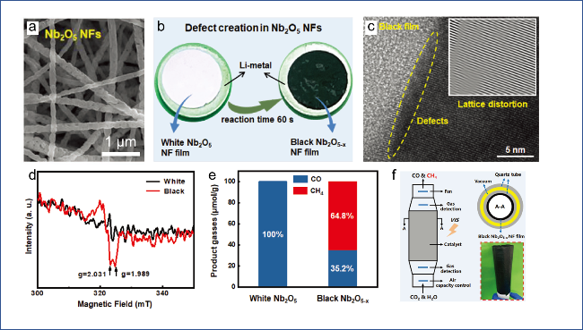
图7 (a)白色Nb2O5纤维SEM图,(b)室温缺陷控制策略,(c)黑色Nb2O5-x纤维TEM图,(d)Nb2O5和Nb2O5-x纤维的EPR表征,(e)光催化CO2还原的选择性,(f)黑色Nb2O5-x纤维膜集成的光催化器件[55]

Fig.7 (a) SEM image of white Nb2O5 fiber,(b) Construction strategy of room-temperature defect,(c) TEM image of black Nb2O5-x fiber,(d) EPR spectra of Nb2O5 and Nb2O5-x fiber,(e) Selectivity of photocatalytic CO2 reduction,(f) Photocatalytic model device integrated with black Nb2O5-x fiber film[55],Copyright 2022,Wiley

High-entropy oxides (HEOs) derived from entropy-driven effects possess stable crystal structures, controllable micro-morphologies, and abundant defect sites, which endow HEOs with efficient catalytic performance[56]. As described in Section 2.2.1, electrospinning is a rapid transition process from liquid precursors to solid fiber formation, making the preparation of HEOs via electrospinning feasible. Zhang et al.[57] proposed a strategy for synthesizing (NiCuMnCoZnFe)3O4 porous high-entropy spinel oxide (HESO) fibrous photocatalysts based on sol-gel electrospinning combined with low-temperature calcination (Fig. 8a, b). Inverse Fourier transform results from HR-TEM images of HESO fibers reveal a disordered cation distribution and numerous vacancy defects on the grain surfaces, indicating inherent lattice strain distortion and defective structures within the HESO grains (Fig. 8c). The in situ DRIFTS results shown in Fig. 8d reveal that *COOH species (1390 cm-1 and 1531 cm-1) appearing on the HESO fiber surface are important intermediates in CO2 reduction; the appearance of symmetric C-H stretching vibration peaks under continuous light irradiation directly confirms CH4 generation. Using HESO fibers, the production rates of CO and CH4 reached 42.8 μmol·g-1·h-1 and 8.7 μmol·g-1·h-1, respectively, within 1 hour (Fig. 8e). They concluded that the high-entropy metal atoms and defective structures on the HESO surface provide active sites for capturing intermediates and protons during CO2 conversion, thereby enabling the synthesis of CO and CH4 (Fig. 8f).
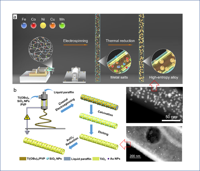
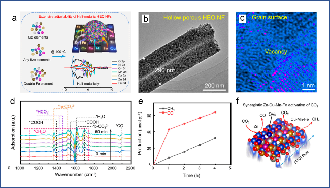
图8 (a)HESO纤维合成策略,(b,c)HESO纤维的TEM和反傅里叶变换结果,(d,e)HESO催化CO2转化的in situ DRIFTS和产量,(f)CO2转化的反应路径[57]

Fig.8 (a) Synthetic strategy of HESO fibers,(b,c) TEM and inverse Fourier Transform results of HESO,(d,e) in situ DRIFTS and products of CO2 conversion catalyzed by HESO,(f) Reaction path of CO2 conversion[57],Copyright 2024,American Chemical Society

3.2 Electrocatalytic CO2 Conversion

Electrocatalysis is a method of realizing chemical reactions through electrochemical processes, that is, by applying voltage to an electrode, thereby introducing a potential difference at the interface between the electrode and electrolyte to drive chemical reactions and accelerate the rate of specific reactions[58]. In recent years, electrocatalysis has made significant progress in many catalytic fields, such as hydrogen/oxygen evolution[59-60], nitrogen-containing substance conversion[61-62], CO2 conversion[63-64], and organic small molecule conversion[65-66], among others.
Electrocatalytic CO2 conversion provides a reliable integrated technical route for the globally rapidly developing photovoltaic, wind, and other distributed energy conversion facilities, enabling the synthesis of chemicals and fuels from renewable electricity through electrocatalytic CO2 conversion, which holds promise for controlling atmospheric CO2 levels and thus mitigating the impact of human activities on ecosystems[67-68]. Based on electrospinning technology, researchers have developed various electrocatalysts for CO2 conversion. Hao et al.[69] proposed a nanofiber-medium thermodynamic-driven atomic migration strategy, achieving the migration of Ni NPs through nitrogen-doped carbon carriers in heated nanofibers containing metal precursors to the VC surface, forming Ni SAs (Figures 9a, b). Ni K-edge FT-EXAFS spectra revealed typical Ni—C and Ni—V bonds but no Ni—Ni bonds in NiSA-VC/NCNFs, indicating that Ni is distributed as single atoms on the VC surface (Figure 9c). In performance comparison, NiSA-VC/NCNFs exhibited stable CO selectivity over a wide voltage range from -0.78 to -1.18 V, with CO Faradaic efficiencies (FECO) exceeding 90% (Figure 9d). Regarding FECO and current density, NiSA-VC/NCNFs outperformed most of the currently reported single-atom catalysts (Figure 9e). In situ ATR-SEIRAS results showed that C—OH and C=O signals appeared on the catalyst surface after applying voltages above 0.58 V and gradually intensified with increasing voltage, indicating the formation of *COOH intermediates during CO2 conversion (Figure 9f). Theoretical calculations of the free energy changes (ΔG) for three key intermediates indicated that VC facilitates CO2 adsorption during catalysis (Figure 9g).
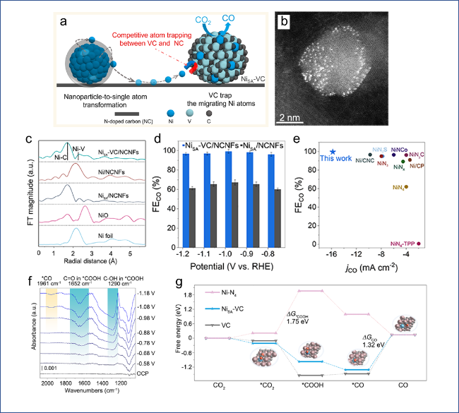
图9 (a)纳米纤维-介质热力学驱动原子迁移策略,(b)NiSA-VC/NCNFs的TEM结果,(c)不同样品的Ni K-edge FT-EXAFS谱,(d)不同样品的FECO,(e)基于单原子催化剂的CO2→CO催化剂性能对比,(f)NiSA-VC/NCNFs催化过程的in situ ATR-SEIRAS谱,(g)不同样品催化CO2→CO过程的ΔG[69]

Fig.9 (a) nanofiber-medium thermodynamically driven atomic migration strategy,(b) TEM result of NiSA-VC/NCNFs,(c) Ni K-edge FT-EXAFS spectra of different samples,(d) FECO of different samples,(e) Comparison of catalytic property of single atomic catalyst for CO2→CO,(f) in situ ATR-SEIRAS spectra of NiSA-VC/NCNFs in catalytic process,(g) ΔG of different samples in CO2→CO process[69],Copyright 2023,American Chemical Society

As described in Section 2.2.2, the most obvious advantage of electrospinning lies in its ability to construct self-supporting membrane-like catalytic materials, which have broad applications in electrocatalysis and battery fields[70-72]. Wang et al.[73] developed a hydrophobic self-supporting membrane electrocatalyst based on the film-forming characteristics of electrospinning, where the catalytic activity originates from asymmetrically coordinated Ni-C-N sites embedded in carbon fibers, while hydrophobicity was achieved through PTFE treatment (Figure 10a). AC-HAADF-STEM and FT-EXAFS results indicate that Ni exists in the catalyst in the form of asymmetrically coordinated single atoms (Figures 10b, c). Electrocatalytic performance testing revealed that NiNF-1100 exhibits optimal FECO and F E H 2 (Figure 10d), along with long-term cycling stability exceeding 280 h (Figure 10e). Failure analysis revealed that the deactivation of NiNF-1100 after prolonged use is due to the loss of surface hydrophobicity, which intensifies HER while simultaneously suppressing CO2 mass transfer (Figure 10f).
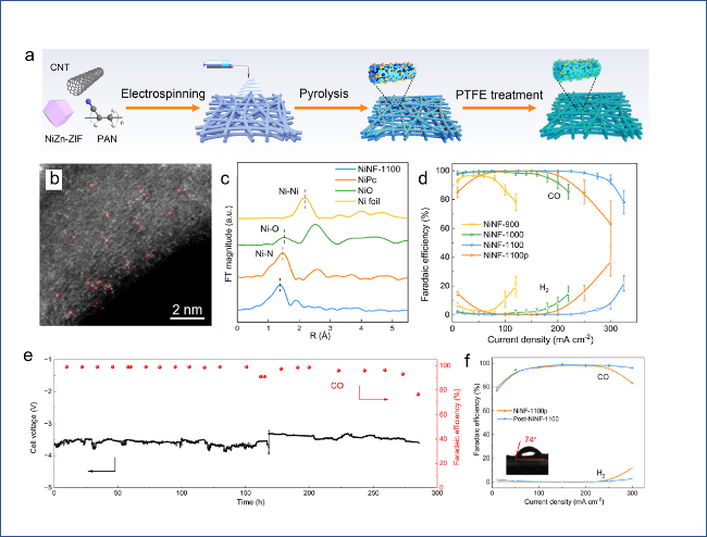
图10 (a)催化剂制备流程,(b)NiNF-1100的HAADF-STEM结果,(c)不同样品的FT-EXAFS结果,(d)不同样品的CO和H2法拉第效率,(e)NiNF-1100的循环稳定性,(f)失活原因分析[73]

Fig.10 (a) Scheme of the fabrication process of catalyst,(b) AC-HAADF-STEM result of NiNF-1100,(c) FT-EXAFS results of different samples,(d) FECO F E H 2 of different samples,(e) recycle stability of NiNF-1100,(f) Failure analysis of NiNF-1100[73],Copyright 2023,Royal Society of Chemistry

3.3 Thermal Catalytic CO2 Conversion

Since the early days of the chemical industry, thermal catalysis has been the protagonist in chemical synthesis processes. Even today, its significant role in the production of essential goods for human life and activities remains substantial. Thermal catalysis is a method that utilizes catalysts to promote chemical reactions under conditions such as heating or pressurization and is widely applied in fields including coal chemical engineering, petrochemicals, and energy catalysis[74-76].
Thermal catalytic CO2 conversion is an effective approach for CO2 transformation and utilization by employing existing chemical reaction equipment. Hu et al.[77] introduced Ni NPs synthesized via a thermal injection method into an electrospinning system, constructing a series of Ni-CeO2 fibers rich in mesopores and VO (Figure 11a), which were applied to the gas-solid phase CO2 methanation reaction. CO2-TPD results of different samples indicated that NiNPs@CeO2 NFs possessed more abundant weakly basic and moderately basic sites, beneficial for the formation of hydrogenation intermediates (Figure 11b). In the catalytic CO2 methanation reaction, NiNPs@CeO2 NFs exhibited high CO2 conversion at low temperatures, along with excellent cycling stability and structural stability (Figure 11c~e). An infrared peak (1508 cm-1) related to bidentate carbonate in in situ DRIFTS confirmed CO2 conversion at low temperatures (Figure 11f). In situ Raman results showed that the Raman signal of VO rapidly disappeared when the temperature exceeded 150 °C, indicating that CO2 was adsorbed and activated by VO before participating in the hydrogenation reaction (Figure 11g).
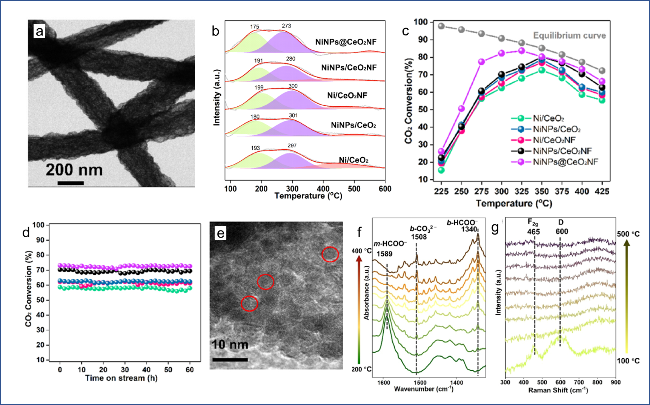
图11 (a)NiNPs@CeO2NFs的TEM图片,(b)不同样品的CO2-TPD结果,(c)不同样品的温度-CO2转化率关系图,(d)不同样品的循环稳定性,(e)NiNPs@CeO2NFs的结构稳定性,(f,g)in situ DRIFTS和in situ Raman结果[77]

Fig.11 (a) TEM image of NiNPs@CeO2NFs,(b) CO2-TPD results of different samples,(c) Temperature-CO2 conversion diagram of different samples,(d) Recycling stability of different samples,(e) Structural stability of NiNPs@CeO2NFs,(f,g) in situ DRIFTS and in situ Raman results[77],Copyright 2022,Elsevier

In addition to the catalytic conversion of single-component CO2 via thermal catalysis, dry reforming of CH4 involving CO2 has attracted widespread attention in recent years due to its potential for directly converting and utilizing both greenhouse gases, providing new insights into CO2 utilization[78-79]. Zhang et al.[80] synthesized various HEOs fibers using electrospinning technology, including (CrMnCoNiFe)3O20, La5MnCuCoNiFeO15, (Ni3MoCoZn)Al12O24, among others (Figure 12a). Taking (Ni3MoCoZn)Al12O24 as an example, TEM and EDS characterization results indicated that each metallic element was uniformly distributed within the fibers, demonstrating successful preparation of the HEOs fibers (Figure 12b). The (Ni3MoCoZn)Al12O24 HEOs fibers were subsequently employed in CO2-CH4 dry reforming, showing a CO2 conversion rate greater than 99% over continuous 100 h operation (Figure 12c). EPR analysis revealed that high concentrations of VO originating from the fibrous morphology contributed to their excellent catalytic performance (Figure 12d). As shown in Figure 12e, signals at 2349 cm-1 in the in situ DRIFTS results corresponded to the strong absorption band of CO2; gradually enhanced signals at 1565 and 1326 cm-1 corresponded to bidentate carbonate and monodentate carbonate species formed during the reaction, respectively, indicating efficient CO2 adsorption and activation processes.
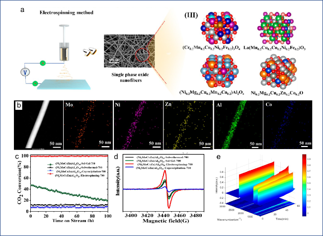
图12 (a)HEOs纤维制备示意图,(b)(Ni3MoCoZn)Al12O24的TEM和EDS表征结果,(c)100 h内的CO2转化率,(d)不同样品的EPR表征,(e)(Ni3MoCoZn)Al12O24催化过程的in situ DRIFTS结果[80]

Fig.12 (a) Scheme of the fabrication process of HEOs fibers,(b) TEM and EDS results of (Ni3MoCoZn)Al12O24,(c) CO2 conversion within 100 h,(d) EPR results of different samples,(e) in situ DRIFTS result of (Ni3MoCoZn)Al12O24 in catalytic process[80],Copyright 2024,American Chemical Society

We summarize the main performance of the aforementioned fibrous catalysts in CO2 conversion, and the results are shown in Table 1. It can be found that fibrous catalysts based on electrospinning exhibit distinct characteristics in photocatalytic, electrocatalytic, and thermocatalytic CO2 conversion. The environmentally friendly photocatalytic process can directly utilize sunlight to drive CO2 conversion, but improving light utilization efficiency and product selectivity is relatively challenging; electrocatalytic CO2 conversion, which directly utilizes distributed energy conversion systems, typically exhibits high Faradaic efficiency; thermocatalytic CO2 conversion using existing chemical reaction equipment demonstrates comprehensive performance advantages in terms of conversion rate and target product selectivity.
表1 不同纤维催化剂用于CO2转化的催化性能对比[55,57,69,73,77,80]

Table 1 Catalytic performance comparison of different fiber catalysts in CO2 conversion[55,57,69,73,77,80]

Fiber catalyst Product Performance descriptor ref
Nb2O5-x CH4 64.8% of selectivity
19.5 μmol·g-1·h-1 of yield rate
55
(NiCuMnCoZnFe)3O4 CO 66.4% of selectivity
15.89 μmol·g-1·h-1 of yield rate
57
NiSA-VC/NCNFs CO FECO=99.2% at -0.98 vs REH 69
NiNF-1100 CO FECO=95% at 282 mA·cm-2 of jCO 73
NiNPs@CeO2NFs CH4 83.7% of conversion
98.2% of selectivity
77
(Ni3MoCoZn)Al12O24 H2/CO >99% of conversion
H2/CO~1
80

4 Conclusion and Prospect

In summary, this article summarizes the design strategies of electrospun fiber catalysts and their applications in CO2 catalytic conversion. Electrospinning is a "top-down" technique for preparing one-dimensional nanomaterials, offering unparalleled flexibility in the hierarchical structure design and multifunctional integration of fiber catalysts. Furthermore, electrospinning holds distinct advantages in designing and fabricating membrane-like self-supported catalysts. Regarding the introduction of active sites in fiber catalysts, common methods include the one-step approach and post-loading method. The one-step method is relatively simple and convenient to operate, whereas the post-loading method provides greater ease in controlling the morphology, distribution, and chemical environment of the active sites. Finally, recent research cases utilizing electrospun fiber catalysts in the fields of photocatalytic, electrocatalytic, and thermal catalytic CO2 conversion are summarized.
The concept of precise catalysis, which has emerged in recent years and spans the entire catalytic process, includes precise catalyst synthesis, precise control of reaction pathways, and precise management of the reaction process. Precise catalyst synthesis is the first step in achieving precise catalysis, and electrospinning demonstrates certain precision in constructing highly dispersed active sites, designing multiscale fibrous structures, and assembling membrane-like catalysts. From the perspective of precise catalyst synthesis, future designs of fibrous catalysts based on electrospinning should also focus on defect engineering at the microscopic scale, heterostructure construction at the mesoscopic scale, and regulation of wettability at the macroscopic scale, as well as the cross-scale synergistic utilization of these features (Fig. 13).
图13 静电纺丝纤维催化剂的多尺度设计策略

Fig.13 Multi-scale design strategy of fiber catalyst based on electrospinning

In addition, the development and design of various efficient catalysts enable traditional thermal energy, emerging electrical energy, and green optical energy to effectively drive the catalytic conversion of CO2. The direct conversion products of CO2 mainly include C1 species such as CO, CH4, and CH3OH, while C2 products are primarily composed of CH2=CH2 and CH3CH2OH. Furthermore, reactions involving CO2, such as dry reforming of methane, coupled N2 reduction for urea synthesis, and CO2 cycloaddition, can produce a wider variety of high-value chemicals. However, several challenges still exist in the design and application of catalysts for CO2 conversion: (1) it is difficult to balance high conversion rates with high selectivity, and stability needs improvement; (2) the reaction conditions for thermal catalytic CO2 conversion are relatively harsh; and (3) the mechanisms of certain complex catalytic reactions remain insufficiently understood. Therefore, future efforts in catalyst design for CO2 conversion should focus on developing highly efficient and precise catalysts, constructing milder reaction systems, expanding the coupling of multiple reactants, and advancing in situ characterization techniques.
Fundamental research guided by objectives and applications represents a new direction for scientific and technological development. At present, fiber catalysts based on electrospinning have achieved significant progress in the field of CO2 conversion. However, several issues warrant attention in future studies: (1) Researchers should actively utilize emerging technological tools such as artificial intelligence and machine learning to assist in the design of catalyst supports and the screening of catalytic active sites; (2) Regarding the high-performance fiber catalysts currently at the laboratory stage, preliminary prototypes for continuous industrial-scale production via electrospinning have begun to emerge. Further scaling up of subsequent catalyst preparation steps, including calcination and introduction of active sites, must also be improved simultaneously; (3) From the perspective of industrial economics, greater emphasis should be placed on economic and time costs, with coordinated design of catalyst structures and long-term stability; (4) From the perspective of green and sustainable development, more attention should be directed toward regeneration of deactivated industrial catalysts and reuse of spent catalysts.
[1]
Jiang M H, Wang H Z, Zhu M F, Luo X J, He Y, Wang M J, Wu C J, Zhang L Y, Li X, Liao X M, Jiang Z J, Jin Z. Chem. Soc. Rev., 2024, 53(10): 5149.

[2]
Yan T X, Chen X Y, Kumari L, Lin J L, Li M L, Fan Q, Chi H Y, Meyer T J, Zhang S, Ma X B. Chem. Rev., 2023, 123(17): 10530.

[3]
Cai M J, Wu Z Y, Li Z, Wang L, Sun W, Tountas A A, Li C R, Wang S H, Feng K, Xu A B, Tang S L, Tavasoli A, Peng M W, Liu W X, Helmy A S, He L, Ozin G A, Zhang X H. Nat. Energy, 2021, 6(8): 807.

[4]
Kong T T, Jiang Y W, Xiong Y J. Chem. Soc. Rev., 2020, 49(18): 6579.

[5]
Jiang W B, Loh H, Low B Q L, Zhu H J, Low J, Heng J Z X, Tang K Y, Li Z B, Loh X J, Ye E Y, Xiong Y J. Appl. Catal. B Environ., 2023, 321: 122079.

[6]
Du Y D, Meng X T, Ma Y J, Qi J, Xu G Y, Zou H Q, Qiu J S. Adv. Funct. Mater., 2024, 34(46): 2408013.

[7]
Bo Y N, Du P Y, Li H, Liu R, Wang C M, Liu H J, Liu D, Kong T T, Lu Z, Gao C, Xiong Y J. Appl. Catal. B Environ., 2023, 330: 122667.

[8]
Yang S D, Guo X, Li X N, Wu T Z, Zou L H, He Z Y, Xu Q, Zheng J J, Chen L, Wang Q Y, Xu Z J. Angew. Chem. Int. Ed., 2024, 63(11): e202317957.

[9]
Wu H Y, Tian B Q, Xu W H, Abdalla K K, Kuang Y, Li J Z, Sun X M. J. Am. Chem. Soc., 2024, 146(32): 22266.

[10]
Yang H P, Lin Q, Zhang C, Yu X Y, Cheng Z, Li G D, Hu Q, Ren X Z, Zhang Q L, Liu J H, He C X. Nat. Commun., 2020, 11: 593.

[11]
Xie Y, Chen J J, Wen J J, Li Z L, Cao F X, Zhang S, Sun Q M, Ning P, Zhang Q L, Hao J M. ACS Catal., 2024, 14(16): 12214.

[12]
Wang J Y, Li R T, Zhang G H, Dong C, Fan Y M, Yang S L, Chen M S, Guo X W, Mu R T, Ning Y X, Li M R, Fu Q, Bao X H. J. Am. Chem. Soc., 2024, 146(8): 5523.

[13]
Cai T, Sun H B, Qiao J, Zhu L L, Zhang F, Zhang J, Tang Z J, Wei X L, Yang J G, Yuan Q Q, Wang W Y, Yang X, Chu H Y, Wang Q, You C, Ma H W, Sun Y X, Li Y, Li C, Jiang H F, Wang Q H, Ma Y H. Science, 2021, 373(6562): 1523.

[14]
Lang R, Du X R, Huang Y K, Jiang X Z, Zhang Q, Guo Y L, Liu K P, Qiao B T, Wang A Q, Zhang T. Chem. Rev., 2020, 120(21): 11986.

[15]
Li Z, Ji S F, Liu Y W, Cao X, Tian S B, Chen Y J, Niu Z Q, Li Y D. Chem. Rev., 2020, 120(2): 623.

[16]
Jing W T, Shen H, Qin R X, Wu Q Y, Liu K L, Zheng N F. Chem. Rev., 2023, 123(9): 5948.

[17]
Li S, Zhou C H, Hu J S, Duan A J, Xu C M, Wang X L. J. Catal., 2023, 426: 153.

[18]
Dou T W, Zhu Y Y, Chu Z Y, Sun L, Li Z J, Jing L Q. Appl. Catal. B Environ. Energy, 2024, 354: 124112.

[19]
Chen X W, Peng M, Cai X B, Chen Y L, Jia Z M, Deng Y C, Mei B B, Jiang Z, Xiao D Q, Wen X D, Wang N, Liu H Y, Ma D. Nat. Commun., 2021, 12: 2664.

[20]
Bai R S, He G Y, Li J Y, Li L, Zhang T J, Wang X X, Zhang W, Zou Y C, Zhang J C, Mei D H, Corma A, Yu J H. Angew. Chem. Int. Ed., 2024, 63(44): e202410017.

[21]
Cai Z X, Xia Y J, Ito Y, Ohtani M, Sakamoto H, Ito A, Bai Y J, Wang Z L, Yamauchi Y, Fujita T. ACS Nano, 2022, 16(12): 20851.

[22]
Gao Z, Dong M, Wang G Z, Sheng P, Wu Z W, Yang H M, Zhang B, Wang G F, Wang J G, Qin Y. Angew. Chem. Int. Ed., 2015, 54(31): 9006.

[23]
Liu Z J, Qi J, Liu M X, Zhang S M, Fan Q K, Liu H P, Liu K, Zheng H Q, Yin Y D, Gao C B. Angew. Chem. Int. Ed., 2018, 57(36): 11678.

[24]
Zhong M X, Xu M J, Ren S Y, Li W M, Wang C, Gao M B, Lu X F. Energy Environ. Sci., 2024, 17(5): 1984.

[25]
Liu R R, Hou L L, Yue G C, Li H K, Zhang J S, Liu J, Miao B B, Wang N, Bai J, Cui Z M, Liu T X, Zhao Y. Adv. Fiber Mater., 2022, 4(4): 604.

[26]
Tucker N, Stanger J J, Staiger M P, Razzaq H, Hofman K. J. Eng. Fibres. Fabr., 2012, 7: 155892501200702S10.

[27]
Ramakrishna S, Fujihara K, Teo W E, Yong T, Ma Z W, Ramaseshan R. Mater. Today, 2006, 9(3): 40.

[28]
Ma S C, Li D Y, Xu R. Prog. Chem., 2024, 36(5): 757.

(马思畅, 李东阳, 徐睿. 化学进展, 2024, 36(5):757.).

[29]
Ji D X, Lin Y G, Guo X Y, Ramasubramanian B, Wang R W, Radacsi N, Jose R, Qin X H, Ramakrishna S. Nat. Rev. Meth. Primers, 2024, 4: 1.

[30]
Zhang C L, Yu S H. Chem. Soc. Rev., 2014, 43(13): 4423.

[31]
Choi S J, Chattopadhyay S, Kim J J, Kim S J, Tuller H L, Rutledge G C, Kim I D. Nanoscale, 2016, 8(17): 9159.

[32]
Chen H Y, Di J C, Wang N, Dong H, Wu J, Zhao Y, Yu J H, Jiang L. Small, 2011, 7(13): 1779.

[33]
Li S, Liu J C, Ma L L, Yu L J, Hou L L, Li D M, Gao S W, Yue G C, Cui Z M, Wang N, Zhao X X, Zhao Y. Adv. Fiber Mater., 2023, 5(1): 252.

[34]
Chen H Y, Wang N, Di J C, Zhao Y, Song Y L, Jiang L. Langmuir, 2010, 26(13): 11291.

[35]
Gao S W, Wang N, Li S, Li D M, Cui Z M, Yue G C, Liu J C, Zhao X X, Jiang L, Zhao Y. Angew. Chem. Int. Ed., 2020, 59(6): 2465.

[36]
Zhu K P, Gao S W, Bai T H, Li H K, Zhang X F, Mu Y, Guo W, Cui Z M, Wang N, Zhao Y. Small, 2024, 2402774.

[37]
Yang B L, Han Q, Han L K, Leng Y M, O'carroll T, Yang X X, Wu G, Xiang Z H. Adv. Mater., 2023, 35: e2208661.

[38]
Chen Y Q, Qiao S S, Tang Y H, Du Y, Zhang D Y, Wang W J, Zhang H, Sun X H, Liu C B. ACS Nano, 2022, 16(9): 15273.

[39]
Yang L P, Zhang X, Yu L X, Hou J H, Zhou Z, Lv R T. Adv. Mater., 2022, 34: 2105410.

[40]
Tong T, Douthwaite M, Chen L, Engel R, Conway M B, Guo W J, Wu X P, Gong X Q, Wang Y Q, Morgan D J, Davies T, Kiely C J, Chen L W, Liu X, Hutchings G J. ACS Catal., 2023, 13(2): 1207.

[41]
Li S W, Xu Y, Chen Y F, Li W Z, Lin L L, Li M Z, Deng Y C, Wang X P, Ge B H, Yang C, Yao S Y, Xie J L, Li Y W, Liu X, Ma D. Angew. Chem. Int. Ed., 2017, 56(36): 10761.

[42]
Luo Q Y, Xu W, Tang S L. Appl. Catal. B Environ., 2022, 312: 121433.

[43]
Zhu H, Sun S H, Hao J C, Zhuang Z C, Zhang S G, Wang T D, Kang Q, Lu S L, Wang X F, Lai F L, Liu T X, Gao G H, Du M L, Wang D S. Energy Environ. Sci., 2023, 16(2): 619.

[44]
Yue G C, Li S, Li D M, Liu J, Wang Y Q, Zhao Y C, Wang N, Cui Z M, Zhao Y. Langmuir, 2019, 35(14): 4843.

[45]
Lin G, Zhang Y, Liu J. Prog. Chem., 2022, 34(11): 2351.

(林刚, 张媛媛, 刘健. 化学进展, 2022, 34(11): 2351.).

[46]
Liu J, Liu X F, Li D M, Yue G C, Li H K, Li S, Gao S W, Wang N, Cui Z M, Bai J, Zhao Y. ChemNanoMat, 2020, 6(8): 1149.

[47]
Sun D K, Shi J W, Ma D D, Zou Y J, Sun G T, Mao S M, Sun L W, Cheng Y H. Chin. J. Catal., 2020, 41(9): 1421.

[48]
Xia P F, Pan X C, Jiang S L, Yu J G, He B W, Ismail P M, Bai W, Yang J J, Yang L, Zhang H H, Cheng M, Li H Y, Zhang Q, Xiao C, Xie Y. Adv. Mater., 2022, 34(28): 2200563.

[49]
Zhao Z F, Nian Y, Shi J F, Xin X, Huang X Y, Shi Y H, Tan J D, Zhang Y, Han Y, Yang D, Jiang Z Y. ACS Catal., 2024, 14(15): 11626.

[50]
Lan Y, Zhang Y, Huang X, Bi Y.. Angew. Chem. Int. Ed., 2024, 63: e202407736.

[51]
Xie Y G, Wang M, Huang Q, Huang Q, Sheng B, Song W J, Sheng H, Zhao J C. Energy Environ. Sci., 2024, 17(13): 4725.

[52]
Yu J, Yu J, Liu J, Wu Z, Kuang S. Prog. Chem., 2024, 36(1): 95.

(于江波, 于婧, 刘杰, 吴占超, 匡少平. 化学进展, 2024, 36(1): 95.).

[53]
Zhou P Y, Wang Y, Yan X R, Gan Y, Xia C K, Xu Y G, Xie M. Appl. Catal. B Environ., 2024, 343: 123485.

[54]
Zhong K, Sun P P, Xu H. Small, 2024, 2310677.

[55]
Lin X, Xia S, Zhang L, Zhang Y, Sun S, Chen Y, Chen S, Ding B, Yu J, Yan J. Adv. Mater., 2022, 34: e2200756.

[56]
Wang Y, Mi J X, Wu Z S. Chem Catal., 2022, 2(7): 1624.

[57]
Zhang L, Xia S H, Zhang X H, Yao Y G, Zhang Y Y, Chen S, Chen Y H, Yan J H. ACS Nano, 2024, 18: 5322.

[58]
Seh Z W, Kibsgaard J, Dickens C F, Chorkendorff I, Nørskov J K, Jaramillo T F. Science, 2017, 355(6321): eaad4998.

[59]
Song L M, Zhang D, Miao H F, Shi Y, Wang M N, Zhao L, Zhan T R, Lai J P, Wang L. Appl. Catal. B Environ., 2024, 342: 123376.

[60]
Liu Y, Xing L W, Liu Y Q, Lian D X, Chen M, Zhang W W, Wu K, Zhu H D, Sun Z Y, Chen W X, Wu P, Wang D S, Ji Y J. Appl. Catal. B Environ. Energy, 2024, 353: 124088.

[61]
Zhang Z H, Niu A H, Lv Y X, Guo H R, Chen J S, Liu Q, Dong K, Sun X P, Li T S. Angew. Chem. Int. Ed., 2024, 63(30): e202406441.

[62]
Du H T, Guo H R, Wang K K, Du X N, Beshiwork B A, Sun S J, Luo Y S, Liu Q, Li T S, Sun X P. Angew. Chem. Int. Ed., 2023, 62(5): e202215782.

[63]
Zhan P, Zhuang J J, Yang S, Li X C, Chen X H, Wen T, Lu L, Qin P Y, Han B X. Angew. Chem. Int. Ed., 2024, 63(33): e202409019.

[64]
Feng J Q, Wu L M, Song X N, Zhang L B, Jia S H, Ma X D, Tan X X, Kang X C, Zhu Q G, Sun X F, Han B X. Nat. Commun., 2024, 15: 4821.

[65]
Zhang Q, Ke Z J, He D, Huang C N, Dai H, Tang C Y, Liu B L, Xiao X H. ACS Catal., 2024, 14(9): 6915.

[66]
Xia Z C, Ma C Y, Fan Y, Lu Y X, Huang Y C, Pan Y P, Wu Y D, Luo Q Y, He Y Q, Dong C L, Wang S Y, Zou Y Q. ACS Catal., 2024, 14(3): 1930.

[67]
Shi K G, Ren Z H, Meng Z, Feng X F. ChemCatChem, 2024, 16(8): e202301308.

[68]
Luo M C, Guo S J. Nat. Rev. Mater., 2017, 2(11): 17059.

[69]
Hao J C, Zhu H, Zhuang Z C, Zhao Q, Yu R H, Hao J C, Kang Q, Lu S L, Wang X F, Wu J S, Wang D S, Du M L. ACS Nano, 2023, 17(7): 6955.

[70]
Gao Y F, Liang S, Liu B M, Jiang C X, Xu C Y, Zhang X Y, Liang P, Elimelech M, Huang X. Nat. Commun., 2023, 14: 2059.

[71]
Yan J H, Dong K Q, Zhang Y Y, Wang X, Aboalhassan A A, Yu J Y, Ding B. Nat. Commun., 2019, 10: 5584.

[72]
Zhang Y, Jiang S, Li Y, Ren X, Zhang P, Sun L, Yang H Y. Adv. Energy Mater., 2022, 13: 2202826.

[73]
Wang M, Lin L, Zheng Z Y, Jiao Z Y, Hua W, Wang G W, Ke X X, Lian Y B, Lyu F L, Zhong J, Deng Z, Peng Y. Energy Environ. Sci., 2023, 16(10): 4423.

[74]
Yang H L, Li G G, Jiang G X, Zhang Z S, Hao Z P. Appl. Catal. B Environ., 2023, 325: 122384.

[75]
Wu X Q, Wei Y X, Liu Z M. Acc. Chem. Res., 2023, 56(14): 2001.

[76]
Zhang W, Lin S, Wei Y, Tian P, Ye M, Liu Z. Natl. Sci. Rev., 2023, 10: nwad120.

[77]
Hu F Y, Ye R P, Jin C K, Liu D, Chen X H, Li C, Lim K H, Song G Q, Wang T C, Feng G, Zhang R B, Kawi S. Appl. Catal. B Environ., 2022, 317: 121715.

[78]
Wen S P, Liang M L, Zou J M, Wang S, Zhu X D, Liu L, Wang Z J. J. Mater. Chem. A, 2015, 3(25): 13299.

[79]
Xie Y S, Xie F Q, Wang L, Peng Y, Ma D H, Zhu L Y, Zhou G L, Wang X Q, Zhang G H. Int. J. Hydrog. Energy, 2020, 45(56): 31494.

[80]
Zhang M Y, Ye J, Gao Y, Duan X L, Zhao J H, Zhang S S, Lu X Y, Luo K L, Wang Q Q, Niu Q, Zhang P F, Dai S. ACS Nano, 2024, 18(2): 1449.

Outlines

/