Home Journals Progress in Chemistry
Progress in Chemistry

Abbreviation (ISO4): Prog Chem      Editor in chief: Jincai ZHAO

About  /  Aim & scope  /  Editorial board  /  Indexed  /  Contact  / 
Review

Critical Issues and Interfacial Design on the Anode Side for Anode-Free Sodium Batteries

  • Jiawen Dai 1 ,
  • Chunlin Xie 1 ,
  • Rui Zhang 1 ,
  • Huanhuan Li 2 ,
  • Haiyan Wang , 1, *
Expand
  • 1 College of Chemistry and Chemical Engineering,Central South University,Changsha 410083,China
  • 2 School of Chemistry and Chemical Engineering,Henan Normal University,Xinxiang 453007,China

Received date: 2024-05-22

  Revised date: 2024-09-09

  Online published: 2024-09-25

Supported by

National Natural Science Foundation of China(22279164)

Hunan Provincial Science and Technology Plan Projects of China(2022RC3050)

Hunan Provincial Science and Technology Plan Projects of China(2017TP1001)

Abstract

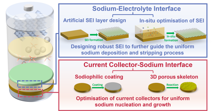
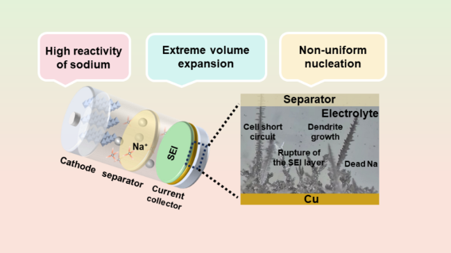
Compared to lithium-ion batteries,sodium-ion batteries have greater advantages in terms of resources,cost,safety,power performance,low-temperature performance,and so on. However,the energy density of sodium-ion batteries is relatively low. To explore broader application prospects,the development of high-specific energy sodium batteries has become a research hotspot in both academia and industry. The anode is considered the key bottleneck constraining the development of the sodium battery industry due to limitations such as the inability of graphite to serve as sodium anodes and the high cost,low Coulombic efficiency,and poor kinetics of mainstream hard carbon materials. In recent years,anode-free sodium batteries (AFSBs) have garnered widespread attention due to their advantages in energy density,process safety,and overall battery cost. However,AFSBs generally show rapid capacity loss due to the rupture of the solid-electrolyte interphase (SEI) layer,increased chemical side reactions,serious dendrite growth and the formation of dead sodium. As the AFSBs operate,active sodium is continuously consumed without additional metallic sodium to replenish it,leading to poor cycling performance and failure of AFSBs. These issues can be attributed to the following characteristics: the high reactivity of sodium,non-uniform nucleation and huge volume expansion. To elucidate the strategies for promoting dendrite-free growth on the anode side of AFSBs,this review focuses on the current collector-sodium interface and sodium-electrolyte interface,including the design of sodiophilic coatings,porous skeleton structure to regulate the sodium nucleation process,and the construction of robust SEI interface,which further guides the homogeneous sodium deposition and stripping process. This systematic review is expected to draw more attention to anode-free configurations and bring new inspiration to the design of high-specific energy batteries.

Contents

1 Introduction

2 Factors affecting sodium deposition on the anode side

2.1 High reactivity of sodium

2.2 Inhomogeneous sodium deposition

2.3 Volumetric deformations

3 Critical differences between sodium and lithium

4 Interface design principles and strategies

4.1 Design principles

4.2 Homogeneous nucleation regulation at the current collector-sodium interface

4.3 Formation of robust SEI at the sodium-electrolyte interface

5 Conclusions and prospects

Cite this article

Jiawen Dai , Chunlin Xie , Rui Zhang , Huanhuan Li , Haiyan Wang . Critical Issues and Interfacial Design on the Anode Side for Anode-Free Sodium Batteries[J]. Progress in Chemistry, 2025 , 37(4) : 551 -563 . DOI: 10.7536/PC240519

1 Introduction

The excessive use of fossil fuels has caused serious energy crises and environmental problems, while renewable energy technologies are rapidly developing[1-4]. Although renewable energies such as solar and wind power have low costs and are inexhaustible, they require integration with energy storage devices to compensate for their intermittent characteristics[5]. Currently, lithium-ion batteries (LIBs), as the primary form of energy storage, have been widely applied in portable consumer electronics, electric vehicles, and grid-scale energy storage systems[1-2,6]. However, due to insufficient lithium reserves and rapidly growing demand, researchers predict that by 2050, more than one-third of global lithium reserves will be depleted[7-9]. In recent years, the lithium-ion battery industry has been severely impacted by fluctuations in lithium carbonate prices[10-11].
Compared with lithium-ion batteries, sodium-ion batteries have significant advantages in terms of resources, cost, safety, power performance, and low-temperature performance. Additionally, their manufacturing processes are compatible, enabling complementary use with lithium-ion batteries. Sodium-ion batteries demonstrate broad application prospects in fields such as two-wheeled vehicles, short-range power, hybrid power systems, energy storage, and engineering equipment[8,12-14]. However, current sodium-ion batteries suffer from relatively low energy density, typically ranging between 140 and 160 Wh·kg-1, which is only about 50% to 80% of that of commercial lithium-ion batteries[15-16]. To expand their application potential, developing high-specific-energy sodium batteries has become a focal point for both academia and industry[8,13,17]. Since graphite and silicon-carbon composites cannot serve as sodium-storage anodes, and mainstream hard carbon materials still face challenges such as high costs[18], low initial Coulombic efficiency, poor kinetic performance, and cell swelling issues[13,19-21], the anode is considered the primary bottleneck currently limiting the industrial development of sodium-ion batteries[22-24]. Sodium metal anodes can enable high-specific-energy sodium batteries; however, metallic sodium is relatively soft, making it difficult to roll or cut into different shapes such as plates, foils, or rods[19]. Currently, there is no commercial sodium foil available on the market[17,25]. Moreover, metallic sodium exhibits extremely high chemical reactivity, readily reacting with the electrolyte[7,12], causing unnecessary electrolyte consumption and the formation of irreversible passivation layers, thus affecting Coulombic efficiency (CE)[7,26].
Recently, AFSBs have received extensive attention, in which the anode is directly composed of either bare current collectors or modified current collectors, thereby enhancing the energy density[27-30]. Compared with conventional sodium-ion batteries, AFSBs can eliminate the anode manufacturing processes including synthesis, mixing, coating, and drying, removing the associated costs of anode fabrication and integration, while also improving battery safety during manufacturing[27-28,31]. However, the design of AFSBs results in a high overpotential for Na+ nucleation on the current collector, aggravating the non-uniformity of Na+ deposition[21,32-33]. Consequently, as cycling proceeds, active sodium is continuously consumed without additional metallic sodium available for replenishment, leading to rapid capacity decay in this system[34-36]. Herein, we present a comprehensive discussion on factors influencing interfacial sodium deposition behavior at the anode side of AFSBs, including the high reactivity of sodium, the non-uniform deposition behavior during cycling, and the significant volume expansion. Designing the anode side has become a key factor affecting the performance of AFSBs. In practical AFSBs, two interfaces exist at the anode side: the current collector-sodium interface and the sodium-electrolyte interface, corresponding respectively to the uniform nucleation and growth of sodium on the surface of the current collector and the formation of a robust solid-state electrolyte interphase[19,37-39]. Subsequently, focusing on these interfaces, this review elaborates strategies for designing the anode side of AFSBs that promote dendrite-free sodium deposition, including designing sodium-affinitive coatings, constructing porous scaffold structures to regulate sodium nucleation, and engineering robust solid-state electrolyte interphases, all aimed at guiding uniform sodium deposition and stripping, ultimately enabling long-lasting AFSBs. Finally, we highlight challenges facing the practical application of AFSBs and provide perspectives for future development.

2 Factors Affecting Sodium Deposition on the Anode Side

2.1 High Reactivity of Sodium

As an alkali metal, sodium readily loses its valence electrons. This characteristic causes an unstable SEI layer to rapidly form and grow when sodium metal comes into contact with the electrolyte, leading to non-uniform and slow passage of sodium ions through the SEI layer, thereby forming sodium dendrites[20,37-38,40]. This not only results in unnecessary consumption of the electrolyte but also reduces the CE due to direct contact between the sodium metal and the electrolyte. Over time, newly formed SEI layers continuously accumulate on the surface of the sodium metal, significantly increasing the interfacial resistance[12].

2.2 Uneven Deposition

During the deposition process, impurities and defects in the current collector materials, as well as their mismatch with the sodium metal lattice, lead to an inhomogeneous electric field distribution[10,12]. This inhomogeneity induces superpotential peaks from non-uniform nucleation within localized electric fields, thereby overcoming nucleation barriers and triggering continuous sodium deposition[25,41-42]. Due to the fragility of the SEI layer, it cannot withstand the pressure caused by the non-uniform deposition of sodium metal[21,26,43], resulting in cracking of the SEI layer around the deposition regions and continuously exposing the sodium metal surface, which promotes the formation of new SEI layers. This process gradually consumes limited sodium and induces dendrite growth[20,44-45]. Archer et al.[38] performed in situ optical visualization measurements under galvanostatic deposition-stripping conditions and captured images of morphological changes in Na at different time points during cycling. As shown in Figure 1, sodium dendrites typically exhibit amorphous needle-like or mossy structures. The initial growth of dendrites tends to occur along the tip direction[19]. However, due to electrostatic shielding effects, the dissolution of sodium dendrites does not occur at the tips but rather preferentially at the base of the dendrites; these physically fractured low-density mossy deposits are referred to as dead sodium[45-46]. These dead sodium particles rapidly transfer to the surface of the electrolyte and fill into the electrolyte and separator, potentially leading to internal short circuits in the battery. Therefore, for sodium batteries, their soft nature implies that short-circuit phenomena are often associated with the accumulation of dead sodium induced by non-uniform deposition[25,32,47-48].
图1 AFSBs面临的挑战

Fig.1 Challenges for AFSBs to address

2.3 Volumetric Expansion Effect

In an anode-free system, the deposition and stripping processes are often accompanied by drastic volume changes due to the lack of a fixed substrate, which significantly exceeds those of intercalation-type anode materials such as graphite and silicon anodes[4,21,49]. Meanwhile, dendritic growth and porous sodium deposition morphology further exacerbate the volume variations during cycling. Herein, a simple and low-cost method (in situ electrochemical dilatometry) can be employed to monitor the thickness changes of electrodes during sodium deposition and stripping processes[50]. This technique involves integrating a displacement sensor into the electrochemical cell to monitor vertical displacement changes of the working electrode during cycling. Combining with the theoretical calculation formula:
h t h e o μ m = 3.6 × 10 4 × Q × M n a F × ρ N a
among them, Q represents the surface density, MNa is the molar mass of sodium (22.99 g·mol-1), F denotes Faraday's constant (96 485 As·mol-1), and ρNa is the density of sodium (0.862 g·cm-3). Taking a copper foil current collector as an example, at the end of the first discharge, the total thickness change on the current collector side is 15.5 μm, significantly greater than the theoretical expected value calculated by Equation (1), which is 10 μm (where Q=1 mAh·cm-2). Additionally, according to Equation (2), the porosity (P) of sodium deposition on the copper foil is approximately 33%[4,31].
P ( % ) = ( 1 - h t h e o h m e a s u r e d ) × 100
severe volume expansion significantly affects the integrity of the SEI layer and the stability of sodium deposition morphology. Dynamic changes in the substrate volume inevitably cause cracks in the SEI layer. The exposed sodium metal regions, due to their lower nucleation energy barrier, become preferred sites for sodium ion deposition, further exacerbating the inhomogeneity of deposition during discharge. Ultimately, this non-uniform deposition leads to the formation of dead sodium. These interrelated issues result in reduced Coulombic efficiency and irreversible capacity loss.[19,51-52]
Generally, anode-free sodium batteries face many challenges (Fig. 1), including the rupture of the SEI layer, increased side reactions, dendrite growth, and the formation of dead sodium. These issues not only threaten battery safety but also accelerate capacity decay[7-8,26]. Notably, all these problems originate from the high reactivity of sodium, its non-uniform deposition, and significant volume expansion. Therefore, to improve the performance and safety of AFSBs, it is essential to conduct in-depth research and address these fundamental challenges.

3 Key Differences Between Sodium and Lithium

At present, numerous studies on lithium metal have emerged in the field of anode-free batteries, aiming to address issues such as volume expansion and lithium dendrites[10-11,33,38,53-57]. Although Na and Li belong to the same alkali metal group, there are still many subtle differences between them, which affect battery performance.
Table 1 lists the differences between sodium and lithium in terms of physical and chemical properties, which may lead to distinct electrochemical behaviors. For example, the larger atomic radius of sodium weakens its attraction to the outermost electrons, making sodium more prone to electron loss and exhibiting higher reactivity compared to lithium. Iermakova et al.[60] conducted optical and electrochemical studies using symmetric cells of metallic sodium and lithium. In conventional carbonate electrolytes, they compared metals immersed in the electrolyte without cycling to those after 30 cycles through infrared spectroscopy. The results showed almost no change in the signal from lithium metal, whereas the signal from sodium metal significantly increased after the electrochemical reaction, indicating poor stability of the SEI layer on the sodium metal surface. Additionally, due to its weaker Lewis acidity, SEI layers primarily composed of sodium salts are more likely to dissolve.
表1 Na与Li物理和化学性质比较

Table 1 Comparison of physical and chemical properties of Na and Li

Parameters Na Li
Atomic radius (Å) 1.86 1.52
Atomic mass (g·mol-1 23 6.9
Ionic radius (Å) 1.02 0.76
Molar volume (cm3·mol-1 23.75 12.97
Crustal abundance (%) 2.3 0.0017
Melting point (K) 371 454
Density (g·cm-3 0.534 0.968
Electron Configurations [2,8,1] [2,1]
The first ionization energy (KJ·mol-1 498.8 520.2
Oxidation-reduction potential (V vs SHE) -2.71 -3.04
Bulk modulus (GPa) 6.3 11
Another difference between Na and Li is that the larger number of electron shells in sodium results in a lower charge density around its ion, leading to reduced desolvation energy for Na+, which facilitates diffusion of solvent molecules through the SEI layer. This contributes to lower interfacial resistance and enhanced ionic conductivity, particularly under high current densities during sodium deposition. Therefore, AFSBs should be designed considering the distinct properties of Na and Li, rather than directly applying strategies used for stabilizing anode-free lithium batteries to sodium battery systems[12,25].

4 Principles and Strategies of Interface Design

4.1 Design Principles

Recently, researchers have proposed various strategies to improve the nucleation and growth process of sodium in AFSBs, including sodium-friendly coatings[28,42,59-64], constructing porous skeleton structures[44,65-68], and optimizing the SEI layer[39,68-71]. Although these studies have achieved certain progress in cycling performance, many of them still fail to fully utilize the well-established nucleation theory for performance optimization. Therefore, introducing nucleation theory is crucial for gaining an in-depth understanding of how these strategies work and further enhancing their performance.
Δ G = - 4 3 π R 3 Δ G V + F ƞ V m + 4 π R 2 γ M E
starting from the classical nucleation theory, the nucleation of a new solid phase has a free energy barrier comparable to the thermodynamics of forming critical atomic clusters[25]. As shown in Equation (3), the Gibbs free energy of a spherical nucleus with radius R is the sum of its volumetric free energy and surface free energy. Here, ΔGv, F, Vm, γME, η, and R represent the Gibbs free energy per unit volume, Faraday constant, molar volume of Na, surface energy at the Na nucleus-electrolyte interface, overpotential, and nucleus radius, respectively. Minimizing the Gibbs energy barrier can improve metal nucleation in anode-free batteries and ultimately enhance their performance[26,35,49,72]. Therefore, sodium deposition behavior can be regulated by reducing both the volumetric free energy and the surface free energy separately.
The nucleation overpotential is a key factor to achieve the reduction of volumetric free energy[25,42]. During the initial stage of the discharge reaction, the voltage initially continuously decreases and then reaches a stable negative voltage plateau as the deposition of sodium increases. Therefore, in the early stages of sodium deposition, a heterogeneous nucleation overpotential spike occurs due to changes in the local electric field, reflecting the electrochemical supersaturation required to overcome the nucleation barrier to initiate sodium deposition. This implies that the sudden voltage drop within the voltage profile of the first cycle is associated with the nucleation overpotential (nμ), which can be estimated by the difference between the bottom of the voltage drop and the subsequent voltage plateau. The plateau potential (np), on the other hand, represents the energy barrier for subsequent Na growth[21,26].
During the deposition of sodium, the current major challenge arises from the poor contact between sodium metal and the current collector, leading to a high nucleation overpotential[71-73]. The sodium nucleation overpotential hinders the smooth deposition of sodium metal and results in the thickening of the SEI layer. Reducing the nucleation potential is critical for promoting more uniform deposition and eliminating side reactions[25]. Additionally, according to Young's equation, the surface free energy is influenced by the contact angle of the metal on the current collector. The contact angle reflects the interfacial energy among the metal, electrolyte, and current collector. A smaller contact angle minimizes the Gibbs free energy barrier and improves the thermodynamics of nucleation[26,49]. By regulating the interfacial energy between the metal and current collector, as well as that between the metal and SEI, a smaller contact angle can be achieved, enhancing the sodiophilicity of the current collector material. Notably, the morphology of sodium metal deposition is also influenced by the lattice structure. When the lattice parameters of the current collector are similar to those of sodium metal, it indicates a closer atomic arrangement. This high compatibility reduces interfacial energy, forming a more stable and uniform deposition layer. Sodium metal exhibits good crystallographic matching with metals such as aluminum (Al), vanadium (V), and zinc (Zn)[21]. This high compatibility favors planar extension rather than vertical growth during Na deposition[63,78], enabling more uniform sodium deposition and suppressing dendrite formation. In contrast, metals such as copper (Cu) and nickel (Ni), which exhibit poor lattice matching, demonstrate higher nucleation overpotentials and uneven sodium deposition[81].

4.2 Regulating the Uniform Nucleation at the Current Collector-Sodium Interface

Sodium metal deposited on the anode side of AFSBs dissolves during stripping and redeposits during subsequent plating processes. Unmodified copper or aluminum foils typically exhibit a relatively rough surface, uneven electron distribution, and high nucleation overpotential, leading to increased local current density and promoting inhomogeneous sodium growth[25,42-43]. Sodium-friendly coating designs and the construction of porous scaffold structures can effectively improve the nucleation process at the current collector-sodium interface, enabling stable and reversible battery cycling.

4.2.1 Sodium-philic Coating Design

Sodium-affinitive coatings improve the sodiophilicity of substrates by employing materials that can form alloys with sodium as the base coating, thereby reducing the nucleation barrier while increasing the number of nucleation sites. Researchers have conducted extensive studies on the sodiophilic properties of Au, Sn, Sb, Cu, Cr, Bi and Mo. Results indicate that among these elements, Au, Sn, Bi and Sb can form alloys with Na, whereas Cu, Cr and Mo cannot[60]. However, due to their high cost, elements such as Au are difficult to apply in industrial production. Yu et al.[61] constructed a Bi-modified layer on copper foil through a simple liquid-phase in-situ reduction reaction (see Figure 2c). After activation treatment, the Bi nanoparticles transformed into Na-rich alloys with sodiophilic properties (Cu@Bi). As shown in Figures 2a and 2b, under conditions of 1 mA·cm-2 and 1 mAh·cm-2, Cu@Bi achieved a long lifespan of 700 h with an average CE as high as 99.5%. During the initial stage of sodium deposition, Cu@Bi exhibited a nucleation overpotential of only 3.5 mV, significantly lower than that of copper foil. Cohn et al.[28] constructed a nano-carbon nucleation layer using conductive carbon black and sodium carboxymethyl cellulose on aluminum foil. Compared with aluminum foil, the nucleation overpotential was reduced from 19 mV to 12 mV, indicating a lower nucleation barrier. Thanks to the presence of highly reactive sp3 carbon sites and oxygen-containing functional groups, the deposited morphology of sodium ions exhibited a uniform block structure. Over 1000 deposition-stripping cycles on this current collector revealed low voltage hysteresis (average 14 mV) and a high average CE of 99.8%. In addition to single coatings, composite coatings have also attracted significant attention. Our research group[64] proposed a co-sputtering strategy to construct a Cu2Sb composite coating. The Cu2Sb coating creates a sodiophilic and stable current collector–sodium interface by suppressing alloying transformation and alleviating volume changes in the coating. Compared with unstable Sb coatings, Cu2Sb alloy coatings with low antimony content retain the sodiophilic Cu2Sb (2 0 0) crystal plane and form low-expansion and irreversible sodium alloys during cycling, maintaining structural stability and sodiophilicity of the coating, inducing the formation of a thin and dense fluorinated SEI layer, greatly enhancing the uniformity of sodium deposition (see Figure 2d, f) and improving ion transport at the interface. As shown in Figure 2e, after sodium stripping, no residual sodium signal was observed on the Cu2Sb@Cu substrate, whereas a strong Na (1 1 0) residual signal was detected on the Cu foil, indicating that Cu2Sb@Cu effectively prevents the formation of dead sodium, unlike the Cu foil which produces significant amounts of dead or low-activity sodium. As shown in Figures 2h and 2i, Cu2Sn@Cu||Na3V2(PO4)3 (NVP) AFSBs retained a discharge capacity of 75.4 mAh·g-1 after 600 cycles with a capacity retention rate of 74.2%, significantly higher than untreated copper foil (capacity retention rate less than 30% after 200 cycles). Mitlin et al.[66] prepared a novel ternary sodium-antimony-tellurium alloy composite, Na2(Sb2/6Te3/6Vac1/6), known as NST-Na, dispersed within electrochemically active metallic sodium via repeated cold rolling and folding (see Figure 2i). This new alloy compound possesses a thermally durable face-centered cubic structure and abundant vacancies. Its surface consists of Na atoms (rather than clusters), thus enhancing planar wetting ability and thermodynamic stability. Additionally, its structural stability during cycling effectively prevents self-degradation. An anode-free NST||Na full battery delivered a stable reversible specific capacity after 100 cycles at a current density of 1 C (see Figure 2j). By balancing the alloying capability and stability of the substrate material, or by controlling the content of sodiophilic substrate materials[79-80], the volume expansion effect of the substrate during sodium deposition can be suppressed, effectively ensuring the long-term stability of the substrate[64].
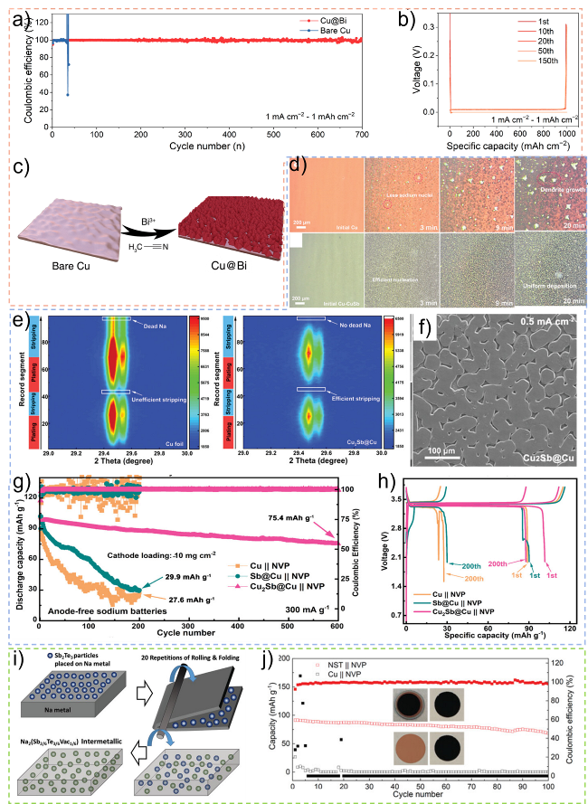
图2 合金化亲钠涂层策略: (a,b) 1 mA·cm-2-1 mAh·cm-2条件下Cu@Bi||Na与Cu||Na沉积剥离库仑效率与Cu@Bi电压曲线;(c) Cu@Bi集流体制备示意图[61];(d) 原位光学显微镜观察Cu及Cu2Sb@Cu在1 mA·cm-2条件下的钠沉积;(e) Cu与Cu2Sn@Cu在1 mA·cm-2-0.5 mAh·cm-2 条件下钠沉积/剥离过程的原位XRD图像;(f) Cu2Sn@Cu钠沉积SEM图像;(g,h) 不同AFSMBs在300 mA·g-1条件下循环稳定性和容量-电压曲线[64];(i) Na2(Sb2/6Te3/6Vac1/6)制备工艺示意图;(j) NST||NVP与Cu||NVP循环性能对比图[66]

Fig.2 Strategies for alloying sodiophilic coatin. (a,b) CE of Na plating/stripping for Cu@Bi||Na and Cu||Na at 1 mA·cm-2 and 1 mAh·cm-2 and the voltage profiles of the Cu@Bi. (c) Schematic diagram for the preparation of the Cu@Bi process[61]. Copyright©2023 MDPI. (d) In situ optical microscope surficial observations of sodium deposition on Cu foil and Cu2Sb@Cu at 1 mA·cm-2. (e) In situ XRD patterns of sodium plating/stripping process on copper foil and Cu2Sb@Cu at 1 mA·cm-2 for 0.5 mAh·cm-2. (f) SEM images of sodium deposition on Cu2Sb@Cu. (g,h) Cyclic stability and capacity-voltage curves of different AFSBs at 300 mA·g-1 [64]. Copyright©2024 Wiley‐VCH GmbH. (i) Schematic illustration for preparing Na2(Sb2/6Te3/6Vac1/6). (j) Comparison of cyclic performance of NST|| NVP and Cu|| NVP [66]. Copyright©2021 Wiley‐VCH GmbH

In the field of composite carbides, Ma et al.[42] anchored Sn4P3 nanocrystals on a reduced graphene oxide (rGO) framework to regulate Na deposition (Figure 3a). Based on galvanostatic electrochemical tests, the Na/Sn4P3@rGO symmetric battery exhibited a long lifespan of up to 500 hours with an extremely low overpotential (<15 mV), at a current density of 1 mA·cm-2 and a deposition capacity of 2 mAh·cm-2, along with minimal nucleation overpotential (4 mV), demonstrating that Sn4P3 with uniform sodiophilic properties can significantly reduce the nucleation barrier and deposition overpotential of Na. Under mechanical bending conditions, stable cycling for 150 cycles with a capacity retention rate of 95.6% was achieved in a full battery with 1.1 mAh (Figure 3b), while also exhibiting excellent rate performance (Figure 3c). Passerini et al.[65] utilized MOF-derived Cu-C composites, as shown in Figure 3d, to construct nucleation buffer layers on conventional current collectors. The abundant nucleation sites provided by the composite materials guided uniform Na deposition, and the carbon framework provided void volume to suppress volume changes during sodium plating and stripping processes. AFSBs using Al-Cu@C as the anode and carbon-coated NVP as the cathode exhibited a high CE value of up to 99.5% and long cycle life (Figure 3e).
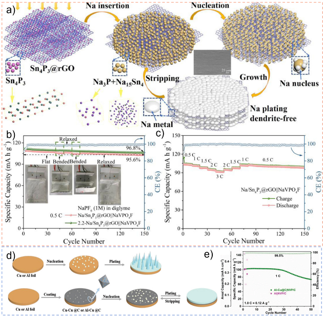
图3 复合碳化物亲钠层策略: (a) Sn4P3@rGO钠沉积剥离示意图;(b) 0.5 C条件下Na/Sn4P3@rGO||NaVPO4F在各种弯曲状态下循环性能;(c) Na/Sn4P3@rGO||NaVPO4F倍率性能[42] (d) Cu-Cu@C与铜箔钠沉积剥离示意图;(e) Al-Cu@C||NVP/C AFSBs在1 C条件下循环性能图[65]

Fig.3 Strategy of Composite Carbide sodiophilic coating. (a) Schematic diagram of sodium deposition and stripping on Sn4P3@rGO. (b) Cycling performance of Na/Sn4P3@rGO||NaVPO4F full cells at 0.5 C under the various bending states. (c) The rate capability of the Na/Sn4P3@rGO|| NaVPO4F full cell at various cycling rates[42]. Copyright©2021 Elsevier. (d) Schematics of Na deposition and stripping on bare Cu and Cu-Cu@C. (e) Cycling performance at 1 C of Al-Cu@C||NVP/C AFSBs[65]. Copyright©2022 Wiley‐VCH GmbH

It is worth noting that the sodium-philic coating strategies often require complex material synthesis and coating procedures. In addition, excessive use of coating materials or polymer binders may reduce the energy density of AFSBs. Modifying traditional current collectors themselves by using other metals or alloys has the advantage of adapting to existing manufacturing facilities, showing promising prospects for large-scale applications. Cheng et al.[27] found that molten sodium on zinc foil exhibited a minimum contact angle of ~32°, in stark contrast to copper's sodium-repelling characteristic with a contact angle reaching ~115° (Fig. 4a, b). Studies revealed that nearly completely reversible Na deposition/stripping could be achieved on the zinc surface, where Zn current collectors formed a NaZn13 alloy interface with initially deposited metallic Na, guiding subsequent Na deposition/stripping behavior. During 500 cycles at 3.0 mAh·cm-2, the efficiency remained almost consistently above 99.9%, and dead sodium formation on the Zn surface was negligible. At 0.5 C, about 90% capacity retention was maintained after 100 cycles (Fig. 4c, d). Matsumoto et al.[63] prepared aluminum current collectors through sequential annealing and fluorination processes (Fig. 4e), optimizing their crystal orientation and surface properties, thereby achieving a highly reversible sodium deposition/stripping process. Using density functional theory calculations, the binding energies of Na atoms adsorbed on Al (1 1 1), Al (1 0 0), oxidized Al (1 0 0), and fluorinated Al (1 0 0) planes were determined as -1.18, -1.37, -1.54, and -2.02 eV, respectively (Fig. 4f). Compared to other substrates, fluorine-treated Al (1 0 0) showed lower binding energy, indicating that annealing and fluorination treatments on the Al (1 0 0) plane played a crucial role in enhancing substrate sodium-philic properties. As shown in Fig. 4g, a full battery composed of this aluminum foil and an NVP cathode achieved high average Coulombic efficiency (~98%) over 50 cycles. Constructing sodium-philic coatings is a powerful measure to address uneven deposition at the current collector-sodium interface; however, considering that most sodium-philic coating designs typically provide only one-dimensional frameworks for sodium metal, structural instability of the substrate adversely affects the long-term cycling performance of batteries as cycling reactions proceed.
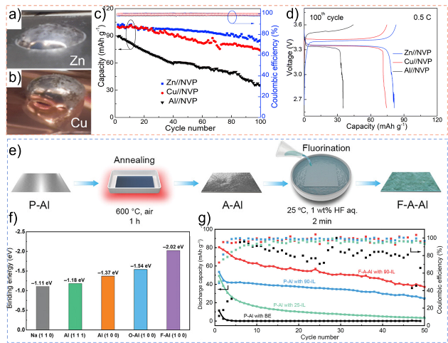
图4 其他金属基集流体策略: (a,b) 熔融Na与Zn和Cu的接触角照片;(c) Zn||NVP、Cu||NVP和Al|NVP AFSBs的循环性能图;(d) Zn|| NVP、Cu||NVP和Al||NVP AFSBs在100th循环中的充/放电压曲线[27];(e) 氟化退火Al (F-A-Al)的制备工艺示意图;(f) 钠原子在不同基底上的结合能;(g) 使用不同电解质的P-Al和F-A-Al基底的循环性能[63]

Fig.4 Strategies for other metal-based current collectors. (a,b) Photographs showing the contact angles of molten Na on Zn and Cu. (c) Cycling performance of Zn||NVP,Cu||NVP and Al||NVP AFSBs. (d) Charge/discharge voltage profiles of Zn||NVP,Cu||NVP and Al||NVP AFSB for 100th cycle[27]. Copyright©2023 The Royal Society of Chemistry. (e) Schematic diagram of the fabrication process of fluorinated annealed Al (F-A-Al). (f) Binding energies of Na atom on different substrates. (g) Cycling performance with P-Al and F-A-Al substrates using different electrolytes[63]. Copyright © 2023 Wiley‐VCH GmbH

4.2.2 Porous Skeleton Structure

This strategy was initially inspired by porous carbon materials, such as graphene and carbon nanotubes. Their high porosity significantly increases the substrate surface area, reduces the local current density, and provides abundant pore structures that serve as additional nucleation sites, effectively accommodating the volume expansion of sodium metal during deposition. This design not only alleviates mechanical stress caused by volume changes but also promotes uniform sodium deposition, suppressing dendrite formation[66-67,84]. To date, various methods have been developed to construct porous skeleton structures. Jiang et al.[44] fabricated a three-dimensional porous copper current collector using a simple chemical dealloying method (see Figure 5b). Compared with traditional two-dimensional copper foil, this structure significantly suppresses dendrite formation (see Figure 5a). After 400 cycles at a current density of 1 mA·cm-2, it exhibits a high cycling efficiency of 99.4% and voltage hysteresis below 20 mV (see Figures 5c and 5d). The superior performance is attributed to the larger specific surface area and excellent electrolyte wettability of the three-dimensional porous copper current collector, which facilitates reducing the actual current density and inhibiting dendrite growth. Liu et al.[67] constructed Cu3P nanowires on copper foil via an in situ growth approach as substrates for sodium deposition (see Figure 5e). Cryo-electron microscopy results demonstrate that the Cu3P component successfully transforms into nano-Cu and Na3P, subsequently forming sodium nuclei. First-principles calculations reveal that Na3P possesses low sodium adsorption energy and diffusion barriers, and the Cu3P@Cu structure demonstrates favorable sodium deposition morphology. An anode-free NVP||Cu3P@Cu full battery delivers a high specific capacity of 76.1 mAh·g-1 after 75 cycles at 0.5 C, with a cycling efficiency reaching 99.5% (see Figures 5f and 5g). A pouch cell shows an initial discharge capacity of 29 mAh at 0.5 C, decreasing to approximately 15 mAh after 30 cycles and remaining stable even after 170 cycles (see Figure 5h).
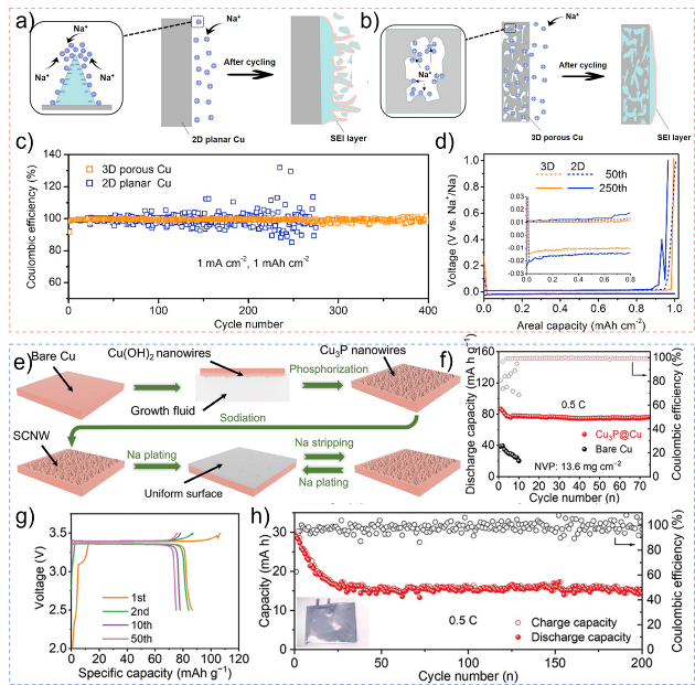
图5 三维结构铜箔改性策略: (a,b) 二维平面铜箔与三维多孔铜箔钠沉积示意图;(c,d) Na-Cu半电池电化学性能[44];(e) Cu3P@Cu集流体的制备以及钠沉积剥离示意图;(f) Cu3P@Cu||NVP AFSBs循环性能;(g) 充放电曲线;(h) Cu3P@Cu||NVP无负极软包电池在0.5 C下的循环性能[67]

Fig.5 Strategies for 3D Copper Foil Structures. Schematic illustration of Na-plating models on different current collectors. (a) 2D planar Cu. (b) 3D porous Cu. (c,d) Electrochemical performance of Na-Cu half cells[44]. Copyright ©2021 Elsevier. (e) The preparation of Cu3P@Cu and Na plating/stripping diagrams. (f) Cycling performance of Cu3P@Cu|| NVP AFSBs. (g) Charge-discharge curves. (h) Cycling performance of Cu3P@Cu||NVP anode-free pouch cells at 0.5 C[67]. Copyright ©2024 Wiley‐VCH GmbH

In addition to structural optimization of copper foil, porous structures can also be constructed on its surface to increase sodium nucleation sites. Wang et al.[69] fabricated a porous fluorinated covalent triazine framework (FCTF) on the current collector surface, which provided excellent sodiophilicity and reduced Na+ consumption during cycling. This could be attributed to the highly ordered layered channels and periodic structure that lower the nucleation overpotential and enable crack-free Na deposition, avoiding excessive consumption of active sodium (see Figure 6a). To evaluate the practical feasibility of FCTF, an assembled pouch cell exhibited 300 stable cycles with nearly no capacity decay under low N/P ratio (1.5), high current density (2 C), and high cathode loading, achieving an energy density of 325 Wh·kg-1 and outstanding rate performance (see Figures 6b, c). Compared with metallic current collectors, lightweight carbon-based current collectors also represent a significant advantage. Cao et al.[68] reported a lightweight three-dimensional carbon current collector obtained through a fungus-assisted biosynthesis method. As shown in Figure 6d, the authors first inoculated basswood with fungi, followed by selective lignin skeleton etching via hydroxyl free radical oxidation reactions spontaneously conducted by the fungi. This fungus-treated basswood (FBW) could be converted into a self-supporting carbon electrode with short-range order after heat treatment (FBWC). The current collector features vertically aligned symmetric channels and high porosity, which reduce local current density and enable uniform sodium deposition. The Na||FBWC asymmetric battery demonstrated stable plating/stripping for over 4500 h with an average CE reaching 99.5%. Although the authors did not present full battery performance, this work provides a new solution for constructing porous skeletal structures for novel AFSBs.
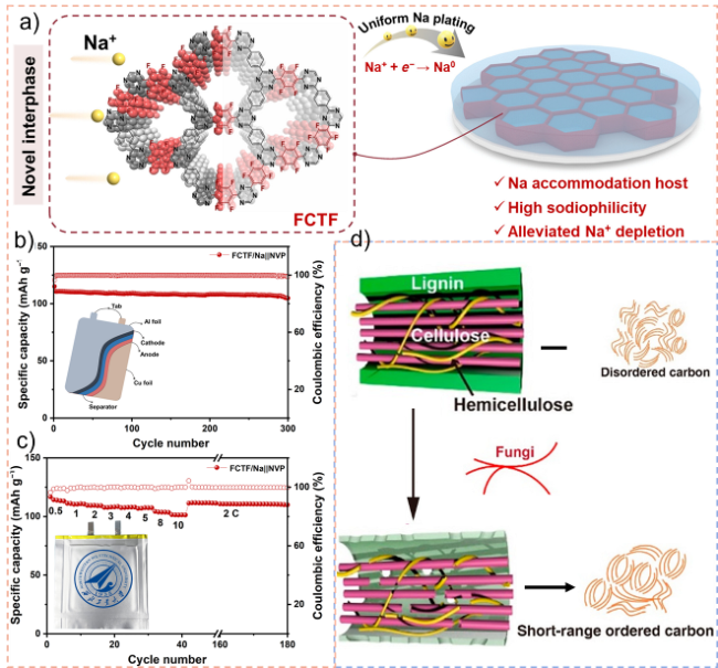
图6 碳化物多孔结构策略: (a) 制备的FCTF与钠沉积剥离示意图;(b) FCTF/Na||NVP软包电池循环性能图;(c) FCTF/Na||NVP软包电池倍率性能[69];(d) 真菌处理椴木炭合成过程示意图[68]

Fig.6 Strategies for porous carbide structures. (a) The preparation of FCTF and Na plating diagrams. (b) Cycling performance of the FCTF/Na||NVP pouch cell. (c) Rate performance of the FCTF/Na||NVP pouch cell[69]. Copyright©2024 AAAS. (d) Schematic diagram for the synthesis process of fungus-treated basswood carbon[68]. Copyright©2021 American Chemical Society

4.3 Formation of a Robust SEI at the Sodium-Electrolyte Interface

The mainstream view currently holds that the SEI layer naturally formed on the sodium metal interface has a bilayer mosaic structure composed of organic and inorganic layers[68]. Although the rich oxygen-containing organic components (e.g., R-ONa, R-OCO2Na, and R(H)-CO2Na) result in low ion diffusion barrier, the presence of soluble long-chain organics makes the SEI structure loose and mechanically weak. As an intermediate layer between sodium and the electrolyte, the thickness and composition of the SEI influence the transport pathways of Na+, ultimately determining the sodium deposition behavior. Current strategies include: (1) constructing an artificial interfacial layer with functions similar to those of the SEI between sodium and the electrolyte to suppress dendrite growth; and (2) optimizing the electrolyte formulation to regulate interfacial reactions. This can be achieved by introducing functional additives into the electrolyte or adjusting its composition to guide the formation of a robust SEI layer, thereby enabling uniform sodium deposition.

4.3.1 Artificial SEI Layer Design

The design principles for a stable artificial SEI include: (1) effectively blocking the reaction between the electrolyte and metallic sodium; (2) possessing good ionic conductivity to facilitate ion transport; (3) having a high elastic modulus to accommodate volume changes during cycling and suppress dendrite growth[75-76]. To date, various inorganic or organic-based artificial SEIs have been reported in the field of sodium metal batteries, including graphene[48], poly(vinylidene fluoride) (PVdF)[36], metal-organic framework materials[73], carbon nanotube paper[45], metal oxide layers, and some alloy-based artificial layers[34,74], which can provide directional guidance for AFSBs. Zhang et al.[39] constructed an organometallic artificial layer composed of PVdF and Bi, achieving smooth and dense sodium deposition (Figure 7a). The authors also demonstrated that Bi in the artificial SEI layer can form Na3Bi with sodium during the first deposition process. In addition to directing the sodium ion flux, Na3Bi can help enhance the mechanical properties of the film. Moreover, the flexible PVdF can suppress volume expansion effects during deposition-stripping cycles and promote the formation of a NaF-rich SEI. At 1 mA·cm-2, the cycle life of the PB@Cu current collector was extended to ~2500 h, showing a high average CE of 99.92%, which contrasts sharply with the fluctuating CE obtained using a copper foil current collector (Figure 7b). PB@Cu AFSBs assembled with an NVP cathode achieved a stable capacity of >90 mAh·g-1 over 150 cycles, significantly higher than the 37.2 mAh·g-1 obtained for NVP||Cu at the 150th cycle (Figure 7c). The electrochemical performance of the PB@Cu current collector originates from the alloyed Na3Bi phase with high ionic conductivity and mechanical strength, as well as the formation of a NaF-rich SEI and rapid sodium ion migration, thereby enabling dendrite-free morphology of sodium deposition at the sodium-electrolyte interface. Furthermore, based on density functional theory (DFT) calculations and ab initio molecular dynamics (AIMD) simulations, Yu et al.[71] predicted that Na2Te exhibits a low Na+ diffusion barrier and a high diffusion coefficient; thus, they designed a Na2Te protective layer with high ionic conductivity, low electronic conductivity, and high mechanical stability. Experimental results showed that Na2Te used as a protective layer can increase the exchange current density in the SEI, reduce the activation energy for sodium migration, and successfully inhibit the growth of sodium dendrites. The Na@Na2Te anode could sustainably cycle for 700 h (1 mA·cm-2, 1 mAh·cm-2) in a low-cost carbonate electrolyte, providing beneficial insights into the design of artificial SEI layers for AFSBs. Organic artificial SEI interfaces exhibit high chemical stability and low sodium ion diffusion barriers; their application in the field of AFSBs not only acts as a robust SEI promoting dendrite-free sodium deposition but also effectively isolates the sodium metal from the liquid electrolyte, reducing irreversible sodium loss during cycling. Zheng et al.[70] adopted a method of modifying the copper foil surface with formate. As shown in Figure 7d, during the first deposition process, the coordinated formate ligands on the Cu surface could spontaneously convert into HCOONa, and the formation of an HCOONa interface on the SF-Cu foil was confirmed using nuclear magnetic resonance (NMR) spectroscopy and surface-enhanced Raman scattering (SERS) spectroscopy. This interface possesses high chemical stability and a low sodium ion diffusion barrier, promoting uniform sodium deposition. Meanwhile, it functions as a robust SEI separating deposited sodium from the liquid electrolyte, reducing irreversible sodium loss (Figure 7e), thereby enhancing the rate capability and cycling stability of the battery. AFSBs composed of SF-Cu||NVP maintained a high capacity retention rate of 88.2% after 400 cycles, with a capacity decay of only 0.03% per cycle and an average CE remaining at 99.97% (Figure 7f).
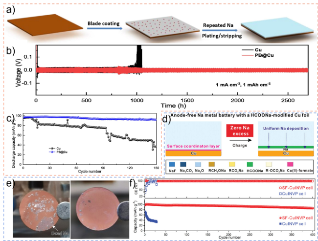
图7 人工SEI层策略: (a) 在PB@Cu集流体上构建人工层以及钠沉积剥离的示意图;(b) 1 mA·cm-2-1 mAh·cm-2条件下电压曲线;(c) NVP|| Cu和NVP||PB@Cu全电池的循环稳定性[39];(d) 具有HCOONa修饰铜箔钠沉积示意图;(e) Cu||Na与SF-Cu||Na电池以1 mA·cm-2和1 mAh·cm-2剥离后光学图像;(f) 0.5 C条件下Cu||NVP与SF-Cu||NVP AFSBs循环性能图[70]

Fig.7 Strategies for artificial SEI Layer. (a) Schematic illustration of the construction of artificial layer and sodium plating/stripping on PB@Cu current collector. (b) Voltage profiles at 1 mA·cm-2 with a fixed cycling capacity of 1 mAh·cm-2. (c) Cycling stability of NVP||Cu and NVP||PB@Cu AFSBs[39]. Copyright©2021 Chinese Academy of Sciences. (d) Na plating diagrams of AFSBs with a HCOONa-modified Cu foil. (e) Optical image of Cu||NVP and SF-Cu||NVP cells stripped at 1 mA·cm-2 and 1 mAh·cm-2. (f) Cycling properties of the Cu||NVP and SF-Cu||NVP cells at 0.5 C[70]. Copyright©2023 Wiley-VCH GmbH

4.3.2 In-situ SEI Layer Optimization

The in-situ optimization design of the SEI layer mainly refers to adjusting the electrolyte formulation or adding functional additives, utilizing the spontaneous reaction between sodium metal and the modified electrolyte, to guide the formation of a robust SEI layer and achieve uniform deposition of sodium.
Huang et al.[41] added a small amount of SnCl2 additive into a conventional carbonate-based electrolyte, achieving in situ formation of Na-Sn alloy phases and a dense NaCl-rich SEI layer, thereby enabling long-term cycling of sodium metal anodes in conventional carbonate electrolytes. Upon contact with sodium metal, due to its high reductive nature, Sn2+ is chemically reduced to Sn, which subsequently alloys with bulk Na to form an alloy interlayer (Figure 8b). Meanwhile, the anion Cl- facilitates the formation of a thin and dense NaCl-rich SEI instead of dendritic or mossy SEI layers (Figure 8a), allowing rapid interfacial ion transfer. As shown in Figure 8c, after 500 h of cycling, the electrode dendrite deposition morphology and voltage hysteresis are significantly reduced in Na||Na symmetric batteries. In the field of AFSBs, Zhang et al.[71] developed a novel electrolyte composed of 1 mol·L-1 NaPF6 and a solvent mixture of diglyme (G2) and tetraglyme (G4) at a volume ratio of 9:1, named NG2410. By optimizing the volumetric ratio of two common linear ether solvents, the cation solvation structure formed by the binary electrolyte promotes flat and dendrite-free planar growth of Na metal on the anode current collector. The SEI formed by unmodified electrolytes typically contains a high proportion of Na2O/Na2O2, often resulting in a porous structure and low mechanical strength under the Kirkendall effect. As shown in Figure 8d, converting NaxO into Na2CO3 can suppress the Kirkendall effect and facilitate the formation of a robust and stable SEI, thus extending battery cycle life. Simultaneously, at 1 mol/L NaPF6, the electrolyte promotes "co-symbiosis" of NaF-rich SEI during Na metal electrochemical deposition on Al-C current collectors, effectively passivating deposited Na metal and enabling dendrite-free planar epitaxial metal growth. Al-C||NG2410||P2-NCO (carbon-coated aluminum foil as current collector, 10 wt% Na2C2O4 (NCO) incorporated into P2 as cathode) AFSBs retained up to 97% capacity retention after 80 cycles with high CE (Figure 8f). As illustrated in Figure 8g, a 40 mAh pouch cell exhibited highly stable charge-discharge curves, achieving an energy density of up to 180 Wh·kg-1. Li et al.[73] demonstrated that by adjusting the electrolyte formulation using an electrolyte composed of 0.9 M NaPF6 and 0.1 mol/L NaBF4 (BPG), decomposition products of flaky NaBF4 displayed a two-dimensional distribution within the SEI, effectively suppressing the formation of dead sodium or sodium dendrites during sodium nucleation growth, and repairing cracks generated during sodium deposition and stripping processes. As shown in Figure 8h, Ah-level cylindrical AFSBs employing BPG electrolyte achieved a cycle life of 260 cycles, delivering high energy densities of 180 Wh·kg-1 (0.91 Ah) and 205 Wh·kg-1 (1.03 Ah) within a voltage range of 2-4 V, comparable to the energy density of lithium iron phosphate-based lithium-ion batteries. Experiments proved that dual-sodium/multi-sodium salt electrolytes contribute to forming more stable SEI layers, effectively guiding uniform sodium deposition and stripping at the sodium-electrolyte interface, providing a key strategy for constructing long-life AFSBs.
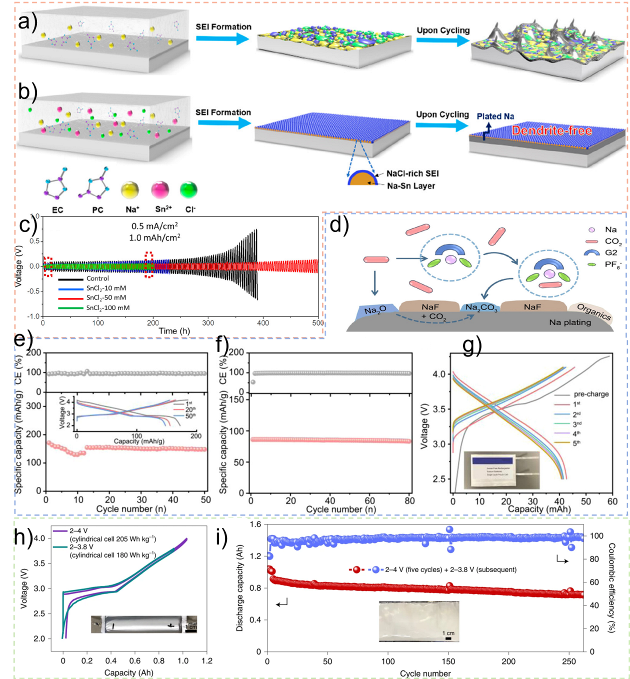
图8 原位SEI层优化策略: (a) 常规碳酸盐电解质中循环过程中形成典型的镶嵌SEI;(b) 原位形成Na-Sn合金层与富含NaCl的SEI;(c) Na/Na对称电池在不同浓度SnCl2下的循环性能[41];(d) CO2转化成碳酸盐的可能途径的示意图;(e) Al-C|| NG2410||P2-NCO电池的循环性能;(f) AFSBs循环性能;(g) GCD 40 mA h Al-C||NG2410||P2-NCO软包电池充放电曲线[41];(h) 在电流密度为0.5 A、不同截止电压下,圆柱形AFSB的第三次恒电流放电-充电曲线;(i) 圆柱AFSBs在电流密度为0.5 A时的循环稳定性[73]

Fig.8 Strategies for in situ optimisation of SEI layers. (a) Formation of typical mosaic SEI cycled in regular carbonate electrolyte. (b) In situ formed Na-Sn alloy layer plus a NaCl-rich SEI. (c) Cycling performance of Na/Na symmetric cells with various concentrations of SnCl2[41]. Copyright©2019,American Chemical Society. (d) Schematic illustration showing possible routes for generating carbonates from the dissolved CO2. (e) Cycling performance and GCD voltage profiles (inset) of Al-C||NG2410||P2-NCO cell. (f) Cycling performance of AFSBs (Al-C||NG2410||P2-NCO). (g) Charge/discharge curves of pouch cell of AFSBs[71]. Copyright©2023,American Chemical Society. (h) The 3rd galvanostatic discharge-charge plots of the cylindrical AFSBs at current density of 0.5 A with diverse cut-off voltages. i) Cycling stability of the cylindrical AFSBs at a current density of 0.5 A[73]. Copyright©2022 The Author(s),under exclusive licence to Springer Nature Limited

5 Conclusion and Prospect

The purpose of studying AFSBs is to develop high-specific-energy sodium batteries that can compete with existing energy storage technologies such as lithium-ion batteries, addressing current shortcomings of lithium-ion batteries in terms of resource availability, cost, safety, power performance, and low-temperature operation. However, compared to traditional sodium metal batteries, AFSBs lack an excess amount of metallic sodium at the anode side, making it critical to improve the utilization efficiency of active sodium and enhance the battery's Coulombic efficiency. In AFSBs, the high reactivity of sodium, non-uniform nucleation, and significant volume expansion during cycling can lead to SEI layer fracture and regeneration, increased side reactions, dendrite growth, and formation of "dead" sodium, all of which consume active sodium and result in rapid capacity decay. Currently, research on anode-free sodium batteries is still in its infancy, and most reported AFSB systems exhibit limited cycle life, remaining far from practical applications. A deep understanding of sodium deposition and stripping behavior at the anode side, along with constructing a stable anode interface, are key factors for improving the cycle life of AFSBs. To address these challenges, this review focuses on the current collector-sodium interface and the sodium-electrolyte interface, discussing design strategies for achieving dendrite-free sodium deposition and stripping in AFSBs. These strategies include designing sodium-affinitive coatings, constructing porous scaffold structures to regulate sodium nucleation, and forming robust solid electrolyte interphases, thereby guiding uniform sodium deposition and dissolution and ultimately enabling long-life anode-free battery systems. The following sections will outline future design principles and considerations for AFSBs.
Current collector design: (1) When selecting a suitable substrate material, if the material can undergo an alloying reaction with sodium during the battery cycling process, the irreversible loss of active sodium should be minimized. Secondly, whether this material causes significant lattice expansion and thus leads to pronounced volume change needs to be considered. To the best of our knowledge, current studies rarely focus on the lattice structure, and further research in this area is required. Finally, whether the sodiophilic property can be maintained after alloying or whether the alloying transformation of the sodiophilic phase can be suppressed are also important factors to consider in the design of current collectors. (2) Although designing multifunctional current collectors through techniques such as introducing carbon layers, cold rolling folding processes, chemical deposition routes, and biosynthesis can improve the cycling stability of AFSBs, for practical applications, complex fabrication processes should be avoided as much as possible when considering preparation methods[82]. (3) For industrial applications, high areal capacity (e.g., ≥3 mAh·cm-2) or high mass loading (e.g., ≥20 mg·cm-2) cathodes are typically used. In such cases, a large amount of sodium metal will deposit on the current collector during charging, leading to significant volume changes and triggering additional stress concentration. When paired with different cathode materials, three-dimensional porous current collectors need to be specifically designed, considering not only the lower limit (the precise deposition volume required) but also the upper limit (the total volume of the current collector), to maintain the overall high volumetric capacity of the battery[32]. Additionally, it must be noted that the three-dimensional porous current collector is a non-active component within the battery, which occupies additional weight and volume, thereby reducing the energy density. Therefore, appropriate lightweight substrate materials should be selected when designing such structures. (4) Design of current collectors for anode-free solid-state batteries: Considering that the contact between the solid electrolyte and the current collector is a two-dimensional planar contact and that the solid electrolyte cannot infiltrate into the pores of the current collector, there may be a lack of effective ion transport channels during cycling, making it difficult to achieve efficient deposition and stripping of sodium metal. Therefore, in the interface design of solid-state batteries, close solid-solid interfacial contact between the solid electrolyte and the current collector must be ensured. High-density current collector materials should be selected to avoid introducing porous current collectors that may create gaps at the interface, hindering the smooth deposition and stripping of sodium metal. Furthermore, applying appropriate stacking pressure physically to the assembled battery can help form a dense solid-solid interfacial contact, which is crucial for reducing contact loss and preventing void formation[83].
Development of advanced characterization techniques: Due to the sensitivity of sodium metal, testing conditions must be strictly controlled to avoid any additional interference. Moreover, the entire battery system is not static during operation, so the designed materials undergo significant morphological and surface condition changes at different charging and discharging stages. Traditional 3D or ex-situ characterizations hardly meet the requirements for monitoring such dynamic processes. With the development of metal batteries, characterization techniques have achieved certain progress; however, most of these techniques are quite costly and time-consuming due to their limited availability. Future efforts should focus on developing more efficient and low-cost characterization methodologies.
Toward practical anode-free batteries: Although coin cells have exhibited favorable cycling performance, the practical performance of anode-free pouch cells and Ah-level cylindrical cells remains unsatisfactory, making it difficult to simultaneously achieve high-rate capacity, high energy density, and excellent cycling stability. Due to structural differences between them, such as lower loading and higher electrolyte usage in coin cells, battery performance is significantly enhanced; however, the situation is quite the opposite for pouch and cylindrical cell systems[32]. Therefore, it is recommended that relevant studies should provide practical test data whenever possible.
[1]
Chen W, Li G D, Pei A, Li Y Z, Liao L, Wang H X, Wan J Y, Liang Z, Chen G X, Zhang H, Wang J Y, Cui Y. Nat. Energy, 2018, 3(5): 428.

[2]
Pan H L, Hu Y S, Chen L Q. Energy Environ. Sci., 2013, 6(8): 2338.

[3]
Chen J P, Chen C X, Hu Z G. Battery Bimonthly, 2019, 49(1): 79.

(陈锦攀, 陈春晓, 胡志刚. 电池, 2019, 49(1): 79.).

[4]
Wang Y X, Wang Y X, Wang Y X, Feng X M, Chen W H, Ai X P, Yang H X, Cao Y L. Chem, 2019, 5(10): 2547.

[5]
Yan J D. Acta Aeronaut. Astronaut. Sin., 2014, 35(10): 2767.

(闫金定. 航空学报, 2014, 35(10): 2767.).

[6]
Zhao C L, Wang Q D, Yao Z P, Wang J L, Sánchez-Lengeling B, Ding F X, Qi X G, Lu Y X, Bai X D, Li B H, Li H, Aspuru-Guzik A, Huang X J, Delmas C, Wagemaker M, Chen L Q, Hu Y S. Science, 2020, 370(6517): 708.

[7]
Hwang J Y, Myung S T, Sun Y K. Chem. Soc. Rev., 2017, 46(12): 3529.

[8]
Yabuuchi N, Kubota K, Dahbi M, Komaba S. Chem. Rev., 2014, 114(23): 11636.

[9]
Grey C P, Hall D S. Nat. Commun., 2020, 11: 6279.

[10]
Lin L D, Suo L M, Hu Y S, Li H, Huang X J, Chen L Q. Adv. Energy Mater., 2021, 11(9): 2003709.

[11]
Shao A H, Tang X Y, Zhang M, Bai M, Ma Y. Adv. Energy Sustain. Res., 2022, 3(4): 2100197.

[12]
Lee J, Kim J, Kim S, Jo C, Lee J. Mater. Adv., 2020, 1(9): 3143.

[13]
Hu Z W, Liu L Y, Wang X, Zheng Q Q, Han C, Li W J. Adv. Funct. Mater., 2024, 34(22): 2313823.

[14]
Delmas C. Adv. Energy Mater., 2018, 8(17): 1703137.

[15]
He H N, Wang H Y, Tang Y G, Liu Y N. Prog. Chem., 2014, 26(4): 572.

(何菡娜, 王海燕, 唐有根, 刘又年. 化学进展, 2014, 26(4): 572.).

[16]
Chu C X, Li R, Cai F P, Bai Z C, Wang Y X, Xu X, Wang N N, Yang J, Dou S X. Energy Environ. Sci., 2021, 14(8): 4318.

[17]
Zheng X Y, Bommier C, Luo W, Jiang L H, Hao Y N, Huang Y H. Energy Storage Mater., 2019, 16: 6.

[18]
Zhao L F, Hu Z, Lai W H, Tao Y, Peng J, Miao Z C, Wang Y X, Chou S L, Liu H K, Dou S X. Adv. Energy Mater., 2021, 11(1): 2002704.

[19]
Li G J, Lou X Y, Peng C B, Liu C T, Chen W H. Chem. Synth., 2022, 2(4): 16.

[20]
Jin Q Z, Lu H F, Zhang Z L, Xu J, Sun B, Jin Y, Jiang K. Adv. Sci., 2022, 9(7): 2103845.

[21]
Cooper E R, Li M, Xia Q B, Gentle I, Knibbe R. ACS Appl. Energy Mater., 2023, 6(22): 11550.

[22]
Zhang S W, Zhang J, Wu S D, Lv W, Kang F Y, Yang Q H. Acta Chim. Sin., 2017, 75(2): 163.

(张思伟, 张俊, 吴思达, 吕伟, 康飞宇, 杨全红. 化学学报, 2017, 75(2): 163.).

[23]
Yue X Y, Ma C, Bao J, Yang S Y, Chen D, Wu X J, Zhou Y N. Acta Phys.-Chim. Sin., 2021, 37(12): 2.

(岳昕阳, 马萃, 包戬, 杨思宇, 陈东, 吴晓京, 周永宁. 物理化学学报, 2021, 37(12): 2.).

[24]
Qiao S Y, Zhou Q W, Ma M, Liu H K, Dou S X, Chong S K. ACS Nano, 2023, 17(12): 11220.

[25]
Wang H, Matios E, Luo J M, Li W Y. Chem. Soc. Rev., 2020, 49(12): 3783.

[26]
Karthika S, Radhakrishnan T K, Kalaichelvi P. Cryst. Growth Des., 2016, 16(11): 6663.

[27]
Dahunsi O J, Gao S Y, Kaelin J, Li B M, Abdul Razak I B, An B W, Cheng Y W. Nanoscale, 2023, 15(7): 3255.

[28]
Cohn A P, Muralidharan N, Carter R, Share K, Pint C L. Nano Lett., 2017, 17(2): 1296.

[29]
Tian Y, An Y L, Wei C L, Jiang H Y, Xiong S L, Feng J K, Qian Y T. Nano Energy, 2020, 78: 105344.

[30]
Yang T Z, Luo D, Liu Y Z, Yu A P, Chen Z W. iScience, 2023, 26(3): 105982.

[31]
Tong Z Z, Bazri B, Hu S F, Liu R S. J. Mater. Chem. A, 2021, 9(12): 7396.

[32]
Dong L W, Zhong S J, Zhang S H, Yuan B T, Liu J P, Xie H D, Zhang C M, Liu Y P, Yang C H, Han J C, He W D. Energy Environ. Sci., 2023, 16(12): 5605.

[33]
Nanda S, Gupta A, Manthiram A. Adv. Energy Mater., 2021, 11(2): 2000804.

[34]
Luo W, Lin C F, Zhao O, Noked M, Zhang Y, Rubloff G W, Hu L B. Adv. Energy Mater., 2017, 7(2): 1601526.

[35]
Deschamps A, Hutchinson C R. Acta Mater., 2021, 220: 117338.

[36]
Hou Z, Wang W H, Chen Q W, Yu Y K, Zhao X X, Tang M, Zheng Y Y, Quan Z W. ACS Appl. Mater. Interfaces, 2019, 11(41): 37693.

[37]
Zhang Q, Luan J Y, Tang Y G, Ji X B, Wang H Y. Angew. Chem. Int. Ed., 2020, 59(32): 13180.

[38]
Zachman M J, Tu Z Y, Choudhury S, Archer L A, Kourkoutis L F. Nature, 2018, 560(7718): 345.

[39]
Zhang J L, Wang S, Wang W H, Li B H. J. Energy Chem., 2022, 66: 133.

[40]
Wang C Z, Wang A X, Ren L X, Guan X Z, Wang D H, Dong A P, Zhang C Y, Li G J, Luo J Y. Adv. Funct. Mater., 2019, 29(49): 1905940.

[41]
Zheng X Y, Fu H Y, Hu C C, Xu H, Huang Y, Wen J Y, Sun H B, Luo W, Huang Y H. J. Phys. Chem. Lett., 2019, 10(4): 707.

[42]
Bai M, Liu Y J, Zhang K R, Tang X Y, Liu S Y, Ma Y. Energy Storage Mater., 2021, 38: 499.

[43]
George T, Weber E R, Nozaki S, Wu A T, Noto N, Umeno M. J. Appl. Phys., 1990, 67(5): 2441.

[44]
Sun J C, Guo C P, Cai Y J, Li J J, Sun X Q, Shi W J, Ai S Y, Chen C C, Jiang F Y. Electrochim. Acta, 2019, 309: 18.

[45]
Sun B, Li P, Zhang J Q, Wang D, Munroe P, Wang C Y, Notten P H L, Wang G X. Adv. Mater., 2018, 30(29): 1801334.

[46]
Wang J Y, Kang Q, Yuan J C, Fu Q R, Chen C H, Zhai Z B, Liu Y, Yan W, Li A J, Zhang J J. Carbon Energy, 2021, 3(1): 153.

[47]
Yao W T, Zou P C, Wang M, Zhan H C, Kang F Y, Yang C. Electrochem. Energ. Rev., 2021, 4(3): 601.

[48]
Wang H, Wang C L, Matios E, Li W Y. Nano Lett., 2017, 17(11): 6808.

[49]
Cheng X B, Zhang R, Zhao C Z, Zhang Q. Chem. Rev., 2017, 117(15): 10403.

[50]
Bao W Z, Wang R H, Li B Q, Qian C F, Zhang Z R, Li J F, Liu F Y. J. Mater. Chem. A, 2021, 9(37): 20957.

[51]
Fatahine M, Guay D, Roué L. J. Appl. Electrochem., 2022, 52(1): 149.

[52]
Menkin S, O’Keefe C A, Gunnarsdóttir A B, Dey S, Pesci F M, Shen Z H, Aguadero A, Grey C P. J. Phys. Chem. C, 2021, 125(30): 16719.

[53]
Lin L D, Qin K, Hu Y S, Li H, Huang X J, Suo L M, Chen L Q. Adv. Mater., 2022, 34(23): 2110323.

[54]
Xie Z K, Wu Z J, An X W, Yue X Y, Wang J J, Abudula A, Guan G Q. Energy Storage Mater., 2020, 32: 386.

[55]
Li N W, Yin Y X, Yang C P, Guo Y G. Adv. Mater., 2016, 28(9): 1853.

[56]
Kim M S, Ryu J H, Deepika, Lim Y R, Nah I W, Lee K R, Archer L A, Il Cho W. Nat. Energy, 2018, 3(10): 889.

[57]
Lin D C, Liu Y Y, Liang Z, Lee H W, Sun J, Wang H T, Yan K, Xie J, Cui Y. Nat. Nanotechnol., 2016, 11(7): 626.

[58]
Lin D C, Liu Y Y, Cui Y. Nat. Nanotechnol., 2017, 12(3): 194.

[59]
Fan L, Li X. Nano Energy, 2022, 3(4): 2100197.

[60]
Iermakova D I, Dugas R, Palacín M R, Ponrouch A. J. Electrochem. Soc., 2015, 162(13): A7060.

[61]
Cheng X L, Li D J, Peng S, Shi P C, Yu H L, Jiang Y, Li S K. Batteries, 2023, 9(8): 408.

[62]
Gao Z Q, Chen Y B, Dong C, Chen F, Huang M L, Ma H T, Wang Y P. Mater. Chem. Phys., 2021, 270: 124809.

[63]
Wu S G, Hwang J, Matsumoto K, Hagiwara R. Adv. Energy Mater., 2023, 13(48): 2302468.

[64]
Xie C L, Wu H, Dai J W, Fu Z H, Zhang R, Ji H M, Zhang Q, Tang Y G, Qiu T, Wang H Y. Adv. Energy Mater., 2024, 14(23): 2400367.

[65]
Li H H, Zhang H, Wu F L, Zarrabeitia M, Geiger D, Kaiser U, Varzi A, Passerini S. Adv. Energy Mater., 2022, 12(43): 2202293.

[66]
Wang Y X, Dong H, Katyal N, Hao H C, Liu P C, Celio H, Henkelman G, Watt J, Mitlin D. Adv. Mater., 2022, 34(1): 2106005.

[67]
Zhang W, Zheng J L, Ren Z A, Wang J C, Luo J M, Wang Y, Tao X Y, Liu T F. Adv. Mater., 2024, 36(15): 2310347.

[68]
Wang P, Zhang G, Wei X Y, Liu R, Gu J J, Cao F F. J. Am. Chem. Soc., 2021, 143(9): 3280.

[69]
Zhuang R, Zhang X H, Qu C Z, Xu X S, Yang J Y, Ye Q, Liu Z, Kaskel S, Xu F, Wang H Q. Sci. Adv., 2023, 9(39): eadh8060.

[70]
Wang C Z, Zheng Y, Chen Z N, Zhang R R, He W, Li K X, Yan S, Cui J Q, Fang X L, Yan J W, Xu G, Peng D L, Ren B, Zheng N F. Adv. Energy Mater., 2023, 13(22): 2204125.

[71]
Yang H, He F X, Li M H, Huang F Y, Chen Z H, Shi P C, Liu F F, Jiang Y, He L X, Gu M, Yu Y. Adv. Mater., 2021, 33(48): 2106353.

[72]
Li Y Q, Zhou Q, Weng S T, Ding F X, Qi X G, Lu J Z, Li Y, Zhang X, Rong X H, Lu Y X, Wang X F, Xiao R J, Li H, Huang X J, Chen L Q, Hu Y S. Nat. Energy, 2022, 7(6): 511.

[73]
Li Y Q, Zhou Q, Weng S T, Ding F, Qi X, Lu J, Li Y, Zhang X, Rong X, Lu Y. Nat. Energy, 2022, 7: 511.

[74]
Zheng J X, Zhao Q, Tang T, Yin J F, Quilty C D, Renderos G D, Liu X, Deng Y, Wang L, Bock D C, Jaye C, Zhang D H, Takeuchi E S, Takeuchi K J, Marschilok A C, Archer L A. Science, 2019, 366(6465): 645.

[75]
Gao Z Q, Chen Y B, Dong C, Chen F, Huang M L, Ma H T, Wang Y P. Mater. Chem. Phys., 2021, 270: 124809.

[76]
Qian J, Li Y, Zhang M L, Luo R, Wang F J, Ye Y S, Xing Y, Li W L, Qu W J, Wang L L, Li L, Li Y J, Wu F, Chen R J. Nano Energy, 2019, 60: 866.

[77]
Xu F, Qu C Z, Lu Q Q, Meng J S, Zhang X H, Xu X S, Qiu Y Q, Ding B C, Yang J Y, Cao F R, Yang P H, Jiang G S, Kaskel S, Ma J Y, Li L, Zhang X C, Wang H Q. Sci. Adv., 2022, 8(19): 7489.

[78]
Xu Pan, Li X, Ni H B, Huang H H, Lin X D, Liu X Y, Fan J M, Zheng M S, Yuan R M, Dong Q F. J. Mater. Chem. A, 2021, 9: 22892.

[79]
Bao C Y, Wang B, Liu P, Wu H, Zhou Y, Wang D L, Liu H K, Dou S X. Adv. Funct. Mater., 2020, 30(52): 2004891.

[80]
Dai J, Wang H, Zhang R, Wang J, Wang P, Qiu T, Wang H Y. Chem. Commun., 2024, 10: 1039.

[81]
Xia X M, Du C F, Zhong S E, Jiang Y, Yu H, Sun W P, Pan H G, Rui X H, Yu Y. Adv. Funct. Mater., 2022, 32(10): 2110280.

[82]
Ni Q, Yang Y J, Du H S, Deng H, Lin J B, Lin L, Yuan M W, Sun Z M, Sun G B. Batteries, 2022, 8(12): 272.

[83]
Deysher G, Oh J A S, Chen Y T, Sayahpour B, Ham S Y, Cheng D Y, Ridley P, Cronk A, Lin S W, Qian K, Nguyen L H B, Jang J, Meng Y S. Nat. Energy, 2024, 10: 1038.

[84]
Kim K H, Lee M J, Ryu M, Liu T K, Lee J H, Jung C, Kim J S, Park J H. Nat. Commun., 2024, 15: 3586.

Outlines

/