
Preparation and Application of Cellulose Nanocrystalline Chiral Liquid Crystals
Received date: 2024-06-28
Revised date: 2024-11-08
Online published: 2025-05-08
Supported by
National Natural Science Foundation of China(22208057)
Central Guidance for Local Science and Technology Development Funds Project(2024L3001)
Cellulose nanocrystals(CNCs)are rod-like nanomaterials with high crystallinity obtained from natural cellulose. CNCs suspensions can form iridescent films with chiral nematic structure through evaporation-induced self-assembly(EISA),showing unique optical properties and presenting specific structural colors,which has great application potential in the fields of anti-counterfeiting,sensing,optoelectronics and so on. Due to the abundant,green and renewable feedstock,CNCs has become the first choice of the new chiral materials. In this paper,the formation mechanism,structure and optical properties of CNCs chiral liquid crystals are introduced,the preparation methods of CNCs chiral liquid crystals which are typical at home and abroad in recent years are reviewed,and the structural colors and regulation methods of CNCs chiral liquid crystals are discussed. The application progress of CNCs chiral liquid crystals in the fields of anti-counterfeiting materials,template materials,other functional materials and biomedicine is also summarized. Finally,the challenges and research prospects of CNCs chiral liquid crystals are addressed.
1 Introduction
2 Formation mechanism and structural characteristics of chiral nematic liquid crystals of cellulose nanocrystals
3 Methods for preparing chiral nematic liquid crystals of cellulose nanocrystals
3.1 Sulfuric acid hydrolysis process
3.2 TEMPO oxidation process
3.3 Other oxidation methods
3.4 Organic acid hydrolysis method
4 Structural regulation of chiral nematic liquid crystals in cellulose nanocrystals
4.1 Influence of length-diameter ratio of CNCs
4.2 The influence of external conditions
5 Application of chiral nematic liquid crystals in cellulose nanocrystals
5.1 Anti-counterfeiting material
5.2 Formwork material
5.3 Other functional materials
5.4 Biomedicine
6 Conclusion and outlook
Siyu Li , Yifan Liu , Yuancai Lv , Xiaoxia Ye , Chunxiang Lin , Minghua Liu . Preparation and Application of Cellulose Nanocrystalline Chiral Liquid Crystals[J]. Progress in Chemistry, 2025 , 37(5) : 670 -685 . DOI: 10.7536/PC240616
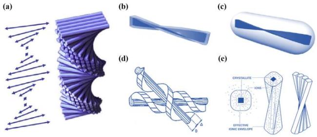
图1 a)手性向列液晶示意图[8];b)CNCs的几何扭转的棒状结构示意图[17];c)CNCs棒状颗粒表现为笔直且光滑的结构示意图[17];d)CNCs几何扭转结构示意图[16];e)CNCs呈螺旋状排列示意图[16]Fig.1 a)Schematic diagram of chiral nematic liquid crystals [8];b)Schematic of the geometrically twisted rod-like structure of CNCs[17];c)Schematic of the rod-like particles of CNCs exhibiting a straight and smooth structure[17];d)Schematic of the geometrically twisted structure of CNCs[16];e)Schematic of the CNCs arranged in a helical shape [16] |
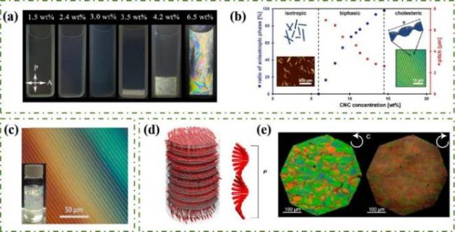
图2 a)CNCs悬浮液相分离过程[19];b)CNCs自组装过程的相图和示意图[8];c)CNCs悬浮液的双折射色和指纹织构[22];d)CNCs手性向列液晶排列的示意图(红色棒为纳米纤维素)[23];e)CNCs手性向列液晶分别在左旋圆偏振片和右旋圆偏振片下的POM图[23]Fig.2 a)Phase separation process of CNC suspension [19];b)Phase diagram and schematic diagram of CNCs self-assembly process[8];c)High concentration CNC suspension showed anisotropic birefringent color and finger texture[22];d)Schematic diagram of chiral nematic liquid crystal arrangement of CNCs(red bars are nanocellulose)[23];e)POM diagram of CNCs chiral nematic liquid crystal under left-handed and right-handed circular polaroids[23] |
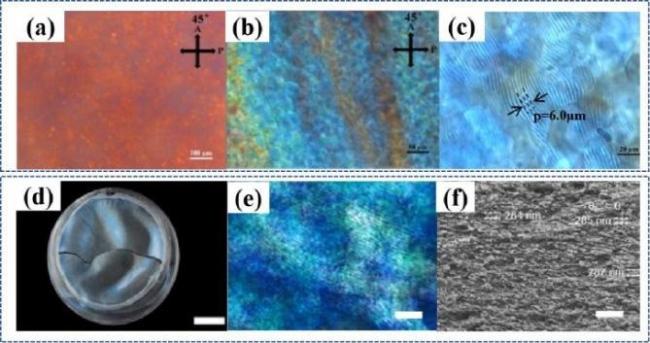
图5 a~c)羧基化CNCs悬浮液的POM照片[39];d)TEMPO氧化法制备羧基化CNCs手性薄膜[40];e)TEMPO氧化法制备羧基化CNCs的POM图[40];f)TEMPO氧化法制备羧基化CNCs手性薄膜的SEM图[40]Fig.5 a~c)POM photos of carboxylated CNCs suspension[39]; d)Preparation of carboxylated CNCs chiral films by TEMPO oxidation method[40];e)POM diagram of carboxylated CNCs prepared by TEMPO oxidation method[40]; f)SEM image of carboxylated CNCs chiral films prepared by TEMPO oxidation method[40] |
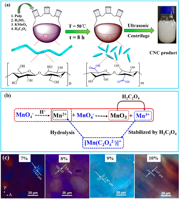
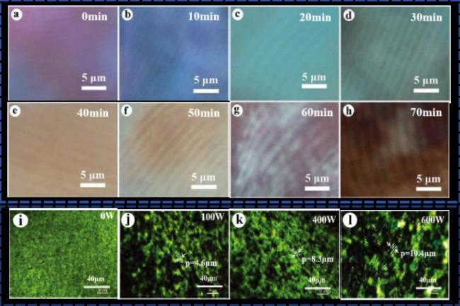
图6 a)高锰酸钾法制备CNCs工艺流程[43];b)高锰酸钾氧化法制备CNCs机理[43];c)高锰酸钾法CNCs悬浮液的POM图[43]Fig.6 a)Process flow of preparation of CNCs by potassium permanganate oxidation method[43];b)Mechanism of preparation of CNCs by potassium permanganate oxidation[43];c)Finger texture formed in 7.0 wt%~10.0 wt% concentration of CNC suspension prepared by potassium permanganate oxidation under polarizing microscope[43] |
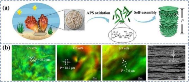
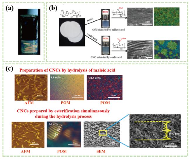
图98 a)草酸水解法制备羧基化CNCs悬浮液的双折射[51];b)硫酸和草酸分别制备CNCs悬浮液的SEM图[52];c)有机酸水解脱脂棉制备羧基化CNCs及其液晶行为研究[53]Fig.8 a)Birefringence of carboxylated CNCs oxalate suspension[51];b)SEM preparation of CNCs suspension by sulfuric acid and oxalic acid respectively[52];c)Preparation of carboxylated CNCs from absorbent cotton by succinic acid hydrolysis and its liquid crys-tal behavior[53] |
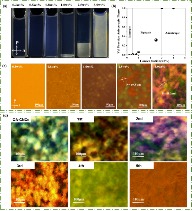
图9 a)OA-CNCs悬浮液不同样品浓度的相分离图[54];b)OA-CNCs悬浮液不同浓度下的相变图[54];c)OA-CNCs悬浮液不同浓度的POM照片[54];d)循环草酸制备的CNCs悬浮液的POM照片[54]Fig.9 a)Phase separation plots of OA-CNCs suspensions at different sample concentrations[54];b)Phase transition plots of OA-CNCs suspensions at different concentrations[54];c)Photographs of POM of OA-CNCs suspensions at different concentrations[54];d)POM photos of CNCs suspension prepared by circulating oxalic acid[54] |
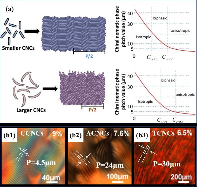
图11 a)不同尺寸CNCs形成手性向列液晶螺距变化以及CNCs悬浮液临界浓度和螺距的变化趋势图[57];b)不同长径比CNCs悬浮液的POM图[60]Fig.11 a)CNCs of different sizes form a diagram of the change of pitch of chiral nematic liquid crystal and a diagram of the change trend of the critical concentration and pitch of CNC suspension[57];b)POM diagrams of CNCs suspension with different aspect ratios[60] |
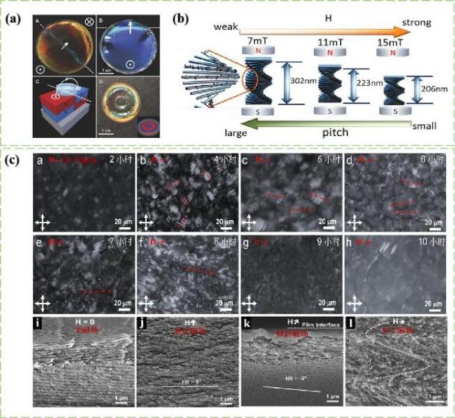
图14 a)商用磁铁(0.5~1.2 T)对CNCs螺距的调控[69];b)含有Fe3O4纳米颗粒的CNCs悬浮液随着磁场强度增大的螺距情况[70];c)在磁场下制备的CNCs手性薄膜的横截面的SEM图[69,72]Fig.14 a)Pitch adjustment with the magnetic field of commercial magnet(0.5~1.2 T)[69];b)Pitch of CNCs suspension containing Fe3O4 nanoparticles with increasing magnetic field intensity[70];c)Scanning electron microscopy(SEM)of cross sections of CNCs chiral films prepared under a magnetic field [69,72] |
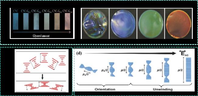
图15 a)含有不同量甘油的固体CNCs手性薄膜的照片[74];b)相对湿度变化时CNC/PEG薄膜的照片[75];c)向CNCs手性薄膜施加压力前后薄膜螺距变化示意图[76];d)在电场增加时CNCs手性液晶的顺序取向和螺距变化示意图[80]Fig.15 a)Photos of solid CNCs chiral films containing different amounts of glycerol[74];b)photos of CNC/PEG films when relative humidity changes[75];c)Schematic diagram of pitch change of CNCs chiral film before and after pressure is applied to the film[76];d)Schematic diagram of sequence orientation and pitch change of the CNCs chiral liquid crystal when the electric field increases[80] |
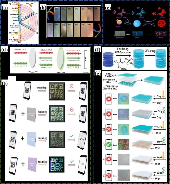
图16 a)CNC/PAA薄膜在不同的相对湿度和旋转角度下表现出不同的颜色双重响应[83];b)CNC/PAA薄膜在不同的相对湿度表现出不同的颜色响应[83];c)CNC-Eu(DA)3-TPEC复合膜在不同紫外光照射下的图像(比例尺:100 μm)[84](上:不同紫外光下观察到蝴蝶图案的薄膜,中:用印章在薄膜上印上“笑脸”,下:在不同紫外光下观察到的纸上印上了“CNC”的字母);d)CNC/CF薄膜结构的双CPL发射产生机制的示意图[85];e)CNC/CF薄膜单光子带隙结构和双光子带隙结构构造的多色二维码图案的应用[85];f)通过溶胀-固化工艺制备CNC/PMTAC复合膜的示意图[86];g)示意图和光学图像显示了由两个CNC/PMTAC膜形成的夹层设计的加密和解码,两个CNC/PMTAC膜由透明单向拉伸膜分开,二维码只能在右手CPL下识别,底层润湿,顶层干燥[86]Fig.16 a)CNC/PAA films show different color dual responses under different relative humidity and rotation angles[83];b)CNC/PAA films show different color responses at different relative humidity[83];c)Image of CNC-EU(DA)3-TPEC composite film under different UV irradiation(scale: 100 μm)[84](Top: butterfly pattern film observed under different UV light,middle: stamp on the film with "smiling face",bottom: paper observed under different UV light with the letter "CNC");d)Schematic diagram of double CPL emission generation mechanism of CNC/CF film structure[85];e)Application of multicolor two-dimensional code pattern of CNC/CF film constructed with single-photon bandgap structure and two-photon bandgap structure[85];f)schematic diagram of CNC/PMTAC composite film prepared by swell-curing process[86];g)schematic and optical images showing the encryption and decoding of a sandwich design formed by two CNC/PMTAC films separated by a transparent unidirectional stretch film. The QR code can only be recognized under the right hand CPL,with the bottom layer wet and the top layer dry[86] |
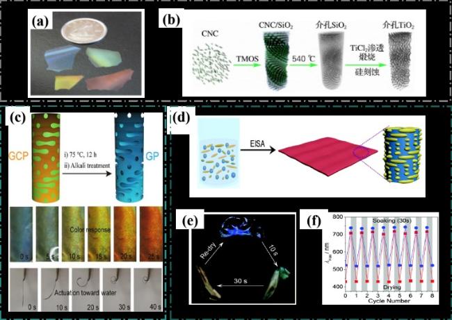
图17 a)手性介孔氧化硅薄膜不同颜色的照片[87];b)CNCs基手性介孔锐钛矿相二氧化钛材料的制备路线图[88];c)GO/CNC复合膜的示意图和物理图像及其表现出快速的水响应变色和弯曲图像[89];d)制备 SAL-CNC复合膜的示意图[90];e)SAL-CNC薄膜在水中浸泡不同时间后的照片[90];f)SAL-CNC薄膜在水中浸泡30 s和干燥之后薄膜的最大反射波长的变化[90]Fig.17 a)Photos of chiral mesoporous silica films in different colors[87]; b)Preparation roadmap of CNCs-based chiral mesoporous anatase phase titanium dioxide[88]; c)schematic and physical images of the GO/CNC composite film and its rapid water-responsive discoloration and bending images[89]; d)Schematic diagram of preparing SAL-CNC composite film[90];e)Photos of SAL-CNC film after soaking in water for different time[90]; f)Maximum reflected wavelength of SAL-CNC film after soaking in water for 30 s and drying[90] |
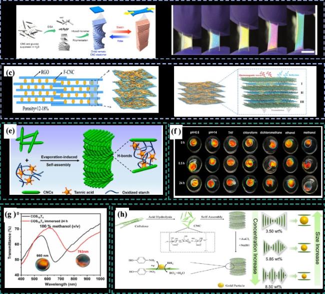
图18 a)CNC/弹性体复合材料制备示意图[92];b)复合膜在交偏光镜下的拉伸照片[92];c)具有珍珠质样层状结构的CNC/RGO复合膜的示意图[93];d)穿过CNC/RGO复合材料的电磁波传递的示意图[93];e)通过EISA制备CNCs/OS/TA膜示意图[94];f)CNCs/OS/TA薄膜在强酸性溶液(pH = 0.5)、碱性溶液(pH = 14)和常用有机溶剂中浸泡不同时间的照片[94];g)CNCs/OS/TA薄膜在甲醇中浸渍24 h之前和之后的紫外透射光谱[94];h)CNC@AuNP的制备和催化应用的示意图[95]Fig.18 a)Schematic diagram of the preparation of CNC/ elastomer composites[92]; b)Stretching photos of composite film under orthogonal polarizer[92]; c)Schematic diagram of CNC/RGO composite film with pearl-like layer structure[93]; d)Schematic diagram of electromagnetic wave transmission through CNC/RGO composites[93]; e)Schematic diagram of CNCs/OS/TA membrane prepared by evaporation-induced self-assembly[94]; f)Photos of CNCs/OS/TA film soaked in strong acidic solution(pH = 0.5),alkaline solution(pH = 14)and common organic solvent for different time[94]; g)Ultraviolet transmission spectra of CNCs/OS/TA films before and after 24 hours impregnation in methanol[94]; h)schematic diagram of the preparation and catalytic application of CNC@AuNP[95] |
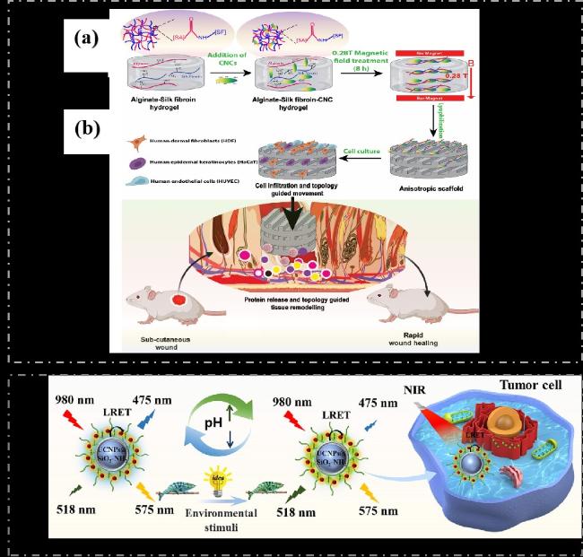
图19 a)在低强度磁场(MF)存在下制备藻酸盐、丝素蛋白和纤维素纳米晶体的各向异性支架的示意图[97];b)CNCs定向排列图案化促进快速细胞浸润、蛋白质释放和拓扑引导的伤口愈合[97];c)基于CNCs的上转换荧光纳米探针的合成工艺[98]Fig.19 a)Schematic diagram of preparing anisotropic scaffolds of alginate,fibroin and cellulose nanocrystals in the presence of low intensity magnetic field(MF)[97];b)Patterning of CNCs directed arrangement promotes rapid cell invasion,protein release,and topologically guided wound healing[97];c)Synthesis process of upconversion fluorescent nanoprobes based on CNCs[98] |
| [1] |
(唐丽荣, 黄彪, 戴达松, 欧文, 李玉华, 陈学榕. 林业科学, 2011, 47(9): 119.).
|
| [2] |
|
| [3] |
|
| [4] |
(丁紫怡, 丁蕊, 郑曦, 陈晓. 福建师范大学学报(自然科学版), 2021, 37(6): 38.).
|
| [5] |
(姜海晶. 吉林大学博士论文, 2019.).
|
| [6] |
|
| [7] |
|
| [8] |
|
| [9] |
|
| [10] |
|
| [11] |
(耿青杰. 华南理工大学博士论文, 2019.).
|
| [12] |
|
| [13] |
|
| [14] |
|
| [15] |
|
| [16] |
|
| [17] |
|
| [18] |
|
| [19] |
(薛岚. 南京林业大学硕士论文, 2012.).
|
| [20] |
|
| [21] |
|
| [22] |
|
| [23] |
(郑洪芝. 吉林大学博士论文, 2018.).
|
| [24] |
|
| [25] |
|
| [26] |
|
| [27] |
|
| [28] |
|
| [29] |
|
| [30] |
|
| [31] |
|
| [32] |
|
| [33] |
|
| [34] |
(代林林, 李伟, 曹军, 李坚, 刘守新. 高分子材料科学与工程, 2016, 32(8): 115.).
|
| [35] |
|
| [36] |
(钱赟. 南京林业大学硕士论文, 2013.).
|
| [37] |
|
| [38] |
|
| [39] |
|
| [40] |
|
| [41] |
(李娜. 青岛科技大学硕士论文, 2019.).
|
| [42] |
|
| [43] |
|
| [44] |
|
| [45] |
|
| [46] |
|
| [47] |
|
| [48] |
|
| [49] |
|
| [50] |
(杜海顺. 天津科技大学硕士论文, 2017.).
|
| [51] |
|
| [52] |
|
| [53] |
|
| [54] |
|
| [55] |
|
| [56] |
|
| [57] |
|
| [58] |
(段敏. 陕西科技大学硕士论文, 2019.).
|
| [59] |
|
| [60] |
|
| [61] |
|
| [62] |
(安邦, 徐明聪, 马春慧, 罗沙, 李伟, 刘守新. 高分子学报, 2022, 53: 211.).
|
| [63] |
|
| [64] |
|
| [65] |
|
| [66] |
(刘思彤, 张大为, 朴光哲. 液晶与显示, 2015, 30(2): 229.).
|
| [67] |
|
| [68] |
|
| [69] |
|
| [70] |
|
| [71] |
|
| [72] |
(李平. 吉林大学博士论文, 2023.).
|
| [73] |
|
| [74] |
|
| [75] |
|
| [76] |
|
| [77] |
|
| [78] |
(郭梦娜. 南京信息工程大学硕士论文, 2022.).
|
| [79] |
|
| [80] |
|
| [81] |
|
| [82] |
|
| [83] |
|
| [84] |
|
| [85] |
|
| [86] |
|
| [87] |
|
| [88] |
|
| [89] |
|
| [90] |
|
| [91] |
|
| [92] |
|
| [93] |
|
| [94] |
|
| [95] |
|
| [96] |
(王珊珊, 韩永和, 林志蓉, 李敏. 福建师范大学学报(自然科学版), 2021, 37: 1.).
|
| [97] |
|
| [98] |
|
/
| 〈 |
|
〉 |