
Preparation and Application of Pore Gradient Unidirectional Moisture Conducting Materials
Received date: 2024-09-04
Revised date: 2025-01-09
Online published: 2025-06-23
Supported by
the Young Elite Scientists Sponsorship Program by JSAST(JSTJ-2023-XH056)
A unidirectional moisture transport material is a specialized type of material designed to transport moisture from one side to the other while simultaneously preventing moisture from moving in the opposite direction. Among these innovative materials, pore-gradient unidirectional moisture transport materials stand out as particularly significant. These advanced materials achieve unidirectional water transport through a carefully engineered gradient of pore sizes within the material, a process driven by the Laplace pressure. Such materials are not only eco-friendly and stable but also operate without requiring any external energy input, making them highly applicable and valuable in fields such as directional water collection, liquid transport, and oil-water separation. This paper first introduces a detailed classification of the various unidirectional moisture transport mechanisms and explains the underlying theoretical mechanisms from an energy perspective. It then reviews and analyzes the different types of pore-gradient materials. Finally, the paper discusses both the current and future applications of unidirectional moisture transport materials, along with a comprehensive analysis of their limitations and potential development directions.
1 Introduction
2 One-way moisture conduction mechanism of porous gradient materials
2.1 Classification of unidirectional moisture conduction mechanism
2.2 The mechanism of unidirectional moisture conduction explained from the perspective of energy
3 Classification of aperture gradient materials
3.1 One-component substrate aperture gradient material
3.2 Multi-component substrate composite aperture gradient materials
4 Applications of aperture gradient materials
4.1 Application of aperture gradient materials in directional water harvesting
4.2 Applications of aperture gradient materials in medical field
4.3 Applications of pore gradient materials in oil-water separation
5 Conclusion and outlook
Hengtao Li , Xiaoke Wang , Guohe Wang , Zhong Wang . Preparation and Application of Pore Gradient Unidirectional Moisture Conducting Materials[J]. Progress in Chemistry, 2025 , 37(7) : 1063 -1073 . DOI: 10.7536/PC240813
表1 液体定向运输材料部分制备技术Table 1 The preparation technology of the directional transport material |
| Technology | Principle | Advantages | Disadvantages |
|---|---|---|---|
| Laser Etching | Utilize a high-energy laser beam to perform microfabrication on materials, forming microchannels or micropores on the material surface that can guide water flow in a specific direction. | relatively high processing accuracy, meeting the requirements for microstructures on materials. | High processing cost. |
| Plasma Treatment | Introduce plasma on one side of the material, causing chemical or physical changes on that surface, thereby altering its wettability. | Plasma treatment can modify material surfaces within a short time and can precisely control the treatment effect. | Plasma treatment equipment is typically expensive and the treatment effect can be influenced by the material. |
| Chemical Vapor Deposition (CVD) | Use gaseous substances to undergo chemical reactions on solid surfaces, thereby generating solid deposits. | Can precisely control the structure and thickness of the deposit. The deposit usually has good adhesion and is not easy to fall off. | Require certain thermal stability of the treated material. The process has a certain level of complexity and operational difficulty. |
| Electrospinning | A technique that uses electric field forces to drive polymer solutions to form fibers. | By adjusting parameters during the electrospinning process, the diameter, morphology, and alignment of fibers can be precisely controlled. | The strength limitations of fiber membranes restrict their application in certain fields. |
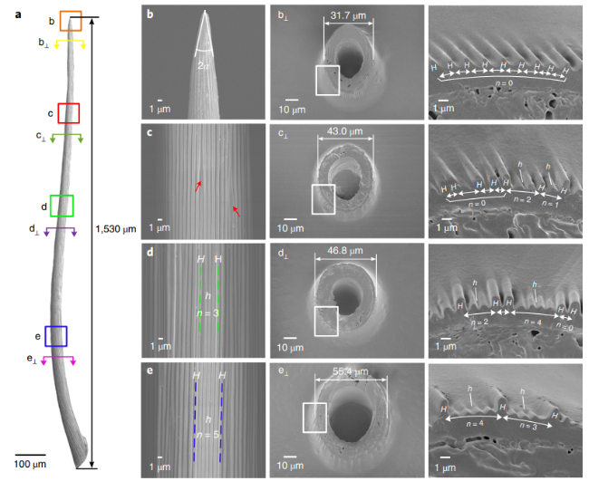
图1 Sarracenia毛状体的外观和表面结构。 a)针状毛体长约1530 μm。b~e,毛状体在纵向视图(b~e)和横截面视图(b⊥-e⊥)中沿长度不同部分的表面。b)毛状体尖端的顶角2α为~17°。c)红色箭头显示了两种不同类型的肋骨纵向延伸。d、e)两条相邻的虚线显示了沿毛状体连续的两条肋。b⊇-e⊥,毛状体的冷冻切片和部分放大的细节(右)[33]Fig.1 Appearance and surface structure of the Sarracenia trichome. a) The needle-shaped trichome is about 1530 μm in length. b~e, The surface of the trichome at different parts along the length in longitudinal view (b~e) and cross-section (b⊥-e⊥). b) The apex angle 2α of the trichome tip is ~17°. c) The red arrows show two different types of longitudinal proliferation of the ribs. One is a rib that divides into two ribs, and the other is a new rib that grows out from two existing ribs. d, e) Two neighboring dotted lines show two successive ribs along the trichome. b⊥-e⊥, Frozen section of a trichome and partially enlarged details (right)[33] |
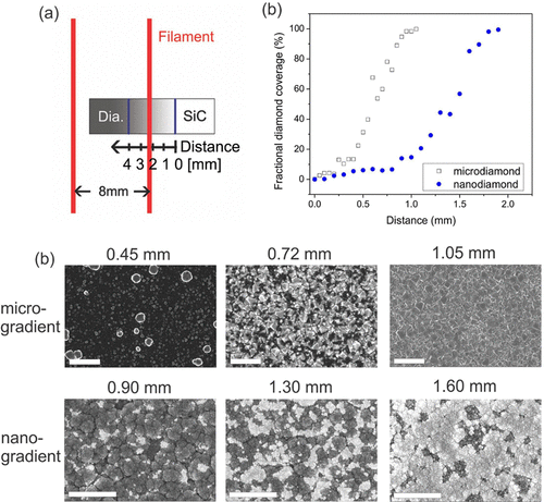
图2 (a)灯丝/衬底结构的俯视图;(b)金刚石/SiC 梯度膜的覆盖率与距离的关系,蓝色圆圈表示纳米金刚石和黑色正方形微金刚石梯度表面;(c)沉积在Si上的纳米梯度(比例尺2 μm)和微梯度(比例尺5 μm)金刚石/SiC 薄膜的 SEM 显微照片[34]Fig.2 (a) Top view of the filament/substrate configuration. (b) Fractional diamond coverage versus distance of the diamond/SiC gradient films, blue circles denote nanodiamond and black squares microdiamond gradient surface. (c) SEM micrographs of nano-gradient (scale bar 2 μm) and micro-gradient (scale bar 5 μm) diamond/SiC film deposited on Si along the gradient axis[34] |
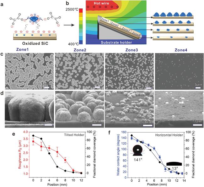
图3 金刚石梯度薄膜的分级制备及润湿性:a)草酸稳定的纳米金刚石颗粒在氧化 SiC 表面自组装播种方案;b)利用倾斜的衬底保持器,采用 HFCVD 方法在 SiC 层上沉积层状金刚石梯度膜;c)扫描电镜图像,显示在(b)相应位置沉积的层状金刚石梯度膜的表面形貌;d)扫描电镜图像显示沉积后的梯度薄膜的横截面形貌;e)在沉积过程中在倾斜支架上合成的表面粗糙度和分数金刚石覆盖率与样本距离的关系,以及样本与样本位置的关系;f)在沉积过程中在水平支架上制备的水接触角和钻石覆盖率与样品的位置之间的关系[35]Fig.3 Hierarchical diamond gradient film fabrication and wettability. a) Scheme of self‐assembly seeding of nanodiamond particles stabilized by oxalic acid on the oxidized SiC surface. b) Deposition of hierarchical diamond gradient film on SiC layer by HFCVD using a tilted substrate holder. c) SEM images showing surface morphology of as‐deposited hierarchical diamond gradient film at positions corresponding to (b). d) SEM images showing cross‐sectional morphology of as‐deposited gradient film. e) Surface roughness (Rz) and fractional diamond coverage versus distance along with the samples versus the samples' position, synthesized on a tilted holder during deposition. f) Water contact angle and fractional diamond coverage versus the position along with the samples, prepared on a horizontal holder during deposition[35] |
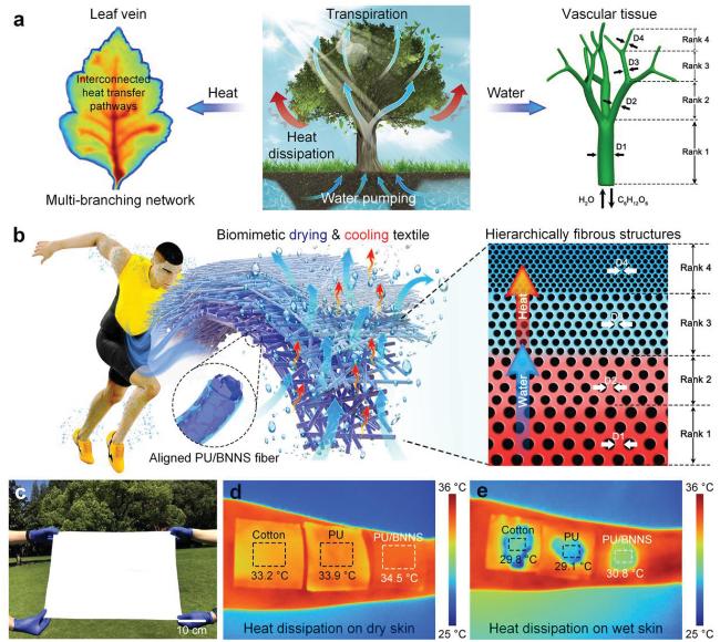
图4 a)植物蒸腾过程示意图。包括水分蒸发和通过其维管组织和叶脉的散热。b) 用于个人干燥和冷却的功能织物的仿生多层纤维膜的汗液释放和散热示意图[42]Fig.4 a) Schematic of the transpiration process in plants. Water evaporation and heat dissipation through their vascular tissue and leaf veins are included. b) Schematic illustrating the sweat release and heat dissipation of the biomimetic multilayer fibrous membrane as a functional textile for personal drying and cooling[42] |
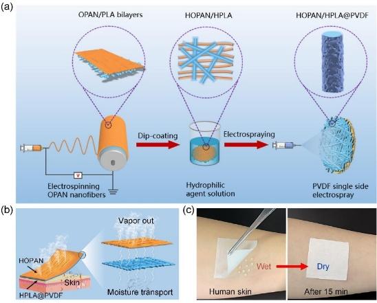
图5 a)HOPAN/HPLA@PVDF纤维膜制备过程示意图;b)所制备的复合纤维膜的汗液运输过程示意图;c)复合纤维膜的快速干燥特性[46]Fig.5 a) Schematic illustrating preparation procedures of HOPAN/HPLA@PVDF moisture-wicking membranes. b) Schematic demonstration of the sweat-release process of the prepared composite membranes. c) The digital images displaying quick-dry property of the prepared composite membranes[46] |
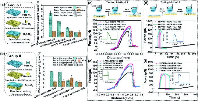
图6 (a)第I组及(b)第II组的纤维结构及集水能力示意图,测试方法1的说明及(c)第I组及(d)第II组的代表性测试结果,水滴(5 µL)被带到膜上接触,然后脱落,测试方法2及(e)第I组及(f)第II组具代表性的测试结果,将水滴(5 µL)附着在膜上而不脱落[56]Fig.6 Schematic illustration of fibrous structure and water harvesting capacity for a) Group I and b) Group II. Illustration of testing Method 1 and the representative test results for c) Group I and d) Group II. Water droplet (5 µL) was brought to contact the membrane and then pulled off. Illustration of testing Method 2 and the representative test results for e) Group I and f) Group II. Water droplet (5 µL) was brought to attach the membrane without pulling off[56] |
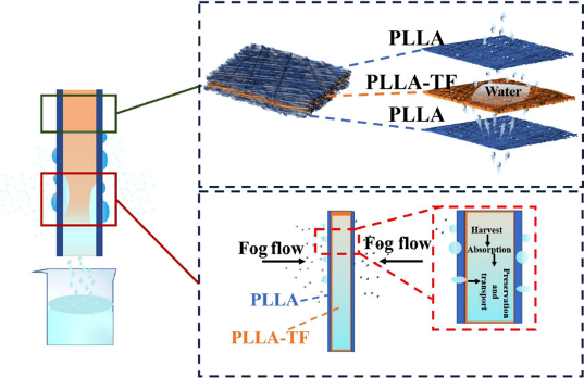
图7 (a)三层纳米纤维膜的静电纺丝过程示意图;(b)通过静电纺丝14 wt% PLLA溶液获得的PLLA纳米纤维的SEM图像和纤维直径分布;(c)通过静电纺丝含有0.5 wt% TF的10 wt% PLLA溶液获得的PLLA-TF纳米纤维的SEM图像和纤维直径分布;(d)三明治结构纳米纤维膜中定向水分运输示意图;(e)实验室集水装置的示意图[48]Fig.7 (a) Schematic illustration of the electrospinning process of trilayered nanofiber membranes. (b) SEM image and fiber diameter distribution of the PLLA nanofibers obtained by electrospinning a 14 wt% PLLA solution. (c) SEM image and fiber diameter distribution of PLLA-TF nanofibers obtained by electrospinning a 10 wt% PLLA solution containing 0.5 wt% TF. (d) Illustration of directional water transport in sandwich-structured nanofiber membranes. (e) Schematic illustration of the laboratory water-harvesting setup[48] |
| [1] |
|
| [2] |
|
| [3] |
|
| [4] |
|
| [5] |
|
| [6] |
|
| [7] |
|
| [8] |
|
| [9] |
|
| [10] |
|
| [11] |
|
| [12] |
|
| [13] |
|
| [14] |
|
| [15] |
|
| [16] |
|
| [17] |
|
| [18] |
|
| [19] |
|
| [20] |
|
| [21] |
(张赛, 董硕, 董东东, 葛效成, 陈振远, 王蕊鑫, 孙召彬, 杨帆. 棉纺织技术, 2024, 52(09):34).
|
| [22] |
|
| [23] |
|
| [24] |
|
| [25] |
|
| [26] |
|
| [27] |
|
| [28] |
|
| [29] |
(谢治云, 蒋培清, 乐鹏涛, 张瞳, 李文斌. 棉纺织技术, 2022, 50(1): 40).
|
| [30] |
|
| [31] |
|
| [32] |
|
| [33] |
|
| [34] |
|
| [35] |
|
| [36] |
|
| [37] |
|
| [38] |
|
| [39] |
|
| [40] |
|
| [41] |
|
| [42] |
|
| [43] |
|
| [44] |
|
| [45] |
|
| [46] |
|
| [47] |
|
| [48] |
|
| [49] |
|
| [50] |
|
| [51] |
(罗鸿, 梅益, 韦函, 周学湫, 覃冰黎, 汪希奎. 表面技术, 2024, 53(22):16).
|
| [52] |
|
| [53] |
|
| [54] |
|
| [55] |
|
| [56] |
|
| [57] |
|
| [58] |
|
| [59] |
|
| [60] |
|
| [61] |
|
| [62] |
|
| [63] |
|
| [64] |
|
| [65] |
|
| [66] |
(陈志强. 陆军军医大学博士论文, 2022).
|
| [67] |
(邵兆银, 周子艺, 冷向锋. 青岛大学学报(医学版), 2024, 60:467).
|
| [68] |
(向婕妤. 武汉大学博士论文, 2023).
|
| [69] |
|
| [70] |
|
| [71] |
|
| [72] |
|
| [73] |
|
| [74] |
(游琰真, 西安石油大学硕士论文, 2023).
|
| [75] |
(高国慧, 于小慧, 王雪琴. 毛纺科技, 2024, 52:128).
|
| [76] |
(曹明, 天津工业大学博士论文, 2023).
|
| [77] |
|
| [78] |
|
| [79] |
|
/
| 〈 |
|
〉 |