Home Journals Progress in Chemistry
Progress in Chemistry

Abbreviation (ISO4): Prog Chem      Editor in chief: Jincai ZHAO

About  /  Aim & scope  /  Editorial board  /  Indexed  /  Contact  / 
Review

Formation Mechanism and Inhibition Strategy of Cathode Alkali Scale in Seawater Direct Electrolysis System

  • Junshu Yuan 1 ,
  • Wei Zhou , 1, * ,
  • Yang Yu 1 ,
  • Xingxing Wang 2 ,
  • Yuming Huang 1 ,
  • Xiaoxiao Meng 1
Expand
  • 1 School of Energy Science and Engineering,Harbin Institute of Technology,Harbin 150001,China
  • 2 CHN ENERGY Yuedian Taishan Power Generation Co.,Ltd.,Taishan 529200,China

Received date: 2024-11-25

  Revised date: 2025-02-15

  Online published: 2025-06-10

Abstract

Hydrogen energy is regarded as an ideal energy carrier for the future. Traditional hydrogen production through fossil fuel reforming fails to fundamentally address carbon emission issues. Direct seawater electrolysis has emerged as a promising hydrogen production technology with significant prospects. Compared to conventional pure-water electrolysis systems,natural seawater exhibits a more complex chemical composition and induces additional side reactions during electrolysis,thereby imposing higher requirements on electrode materials and electrolyzer structural design. The chlorine evolution reaction (CER) at the anode and calcium/magnesium ion precipitation at the cathode constitutes two critical challenges in direct seawater electrolysis. While substantial research has been reported in recent years regarding the mechanisms and suppression strategies of CER,comparatively fewer studies have systematically addressed the fundamental mechanisms and inhibition approaches for cathodic calcium/magnesium deposition. Practical hydrogen production processes require particular attention to electrode performance degradation caused by such inorganic precipitates,including increased mass transfer resistance and reduced electrolysis efficiency. This review initiates from the formation mechanisms of calcium/magnesium precipitation on cathode surfaces,elaborates on the fundamental principles and technical challenges of direct seawater electrolysis,and critically summarizes recent advances in suppression strategies against cathodic inorganic deposition. Furthermore,perspectives on future research directions for seawater electrolysis technology are provided,emphasizing the need for comprehensive investigations into electrode-electrolyte interfaces and scalable system optimization.

Contents

1 Introduction

2 Principle of hydrogen production by seawater electrolysis

2.1 Principle of cathode hydrogen evolution reaction

2.2 Principle of anodic oxygen evolution reaction

3 Problems and challenges in producing hydrogen from seawater electrolysis

4 Formation mechanism and inhibition method of alkaline scale of cathode in seawater by direct electrolysis

4.1 Formation mechanism of cathode alkaline scale

4.2 High performance HER catalyst

4.3 Electrode protective coating

4.4 Regulation of local reaction conditions in seawater

4.5 Polarity reversal

4.6 Design of electrolytic cell and electrolytic system

5 Conclusion and outlook

Cite this article

Junshu Yuan , Wei Zhou , Yang Yu , Xingxing Wang , Yuming Huang , Xiaoxiao Meng . Formation Mechanism and Inhibition Strategy of Cathode Alkali Scale in Seawater Direct Electrolysis System[J]. Progress in Chemistry, 2025 , 37(8) : 1142 -1155 . DOI: 10.7536/PC241113

1 Introduction

Currently, about 65% of global energy demand is met by non-renewable sources such as fossil fuels[1]. The extensive use of fossil fuels has brought about a series of environmental issues worldwide, including depletion of natural resources, greenhouse gas emissions, and climate change[2], severely impacting industrial and societal development. Therefore, it is necessary to find renewable energy sources to replace traditional fossil fuels and meet the future needs of normal human production and life.
In the renewable energy system, hydrogen energy is one of the most important energy sources. As a fuel, its combustion produces only water, with no excess carbon emissions. Its flammability range in air is relatively wide, reaching 4% to 75%, and in oxygen, it can extend from 4% to 95%[3]. Hydrogen has a high calorific value, with an energy density (140 MJ/kg) more than twice that of solid fuels (50 MJ/kg), making it highly efficient, environmentally friendly, and pollution-free. Moreover, unlike solar and wind energy, hydrogen use is not limited by geographic location or external environmental conditions, thus addressing the intermittency issues of renewable energy sources and serving as an ideal carrier for future energy[4-5]. Currently, the global annual hydrogen production is approximately 500 billion m3, with about 96% produced through fossil fuel reforming and only 4% generated via water electrolysis[6].
Currently, the main laboratory methods for hydrogen production via water electrolysis include alkaline water electrolysis (AWE), proton exchange membrane electrolysis (PEM), and solid oxide electrolysis (SOEC)[7]. These processes typically occur in an electrolyte based on pure water, with conductivity enhanced by adding various electrolytes to the pure water[8]. However, due to the high cost of preparing pure water and electrolytes, it is difficult to ensure a continuous supply of pure water in remote coastal areas. Additionally, freshwater resources on Earth are limited, with approximately 30% of the global population living in water-scarce regions, making water depletion a serious issue. As a result, it is challenging to achieve a stable and continuous supply of hydrogen energy in practical electrolysis operations[9]. In contrast, using seawater for electrolytic hydrogen production offers inherent advantages. First, seawater resources are abundant, accounting for 96.53% of the Earth's total water resources. Second, seawater contains various metallic and non-metallic ions, providing higher electrical conductivity for the electrolysis process. Finally, seawater is generally slightly alkaline, eliminating corrosion issues for electrodes[8]. Utilizing seawater for electrolysis holds promise for achieving sustainable and low-cost hydrogen production.
Currently, in the field of electrolytic hydrogen production, seawater is mainly used after desalination. In recent years, seawater reverse osmosis (SWRO) technology has made significant progress. With continuous improvements in membranes, enhanced efficiency of energy recovery devices, and optimization of reverse osmosis (RO) processes, the operating costs and energy requirements of seawater desalination have further decreased[10]. In contrast, direct seawater electrolysis technology still faces many challenges. First, during direct seawater electrolysis, the anode simultaneously undergoes oxygen evolution reaction (OER) and chlorine evolution reaction (CER). These two reactions compete for active sites on the electrode surface during electrolysis, reducing the overall efficiency. Additionally, the products of the CER reaction have a certain corrosive effect on the electrode and electrolyzer materials, affecting their service life[11]. Second, due to limitations in mass transfer rates within the system, after hydrogen gas is generated and released from the cathode surface, the remaining large amount of OH-cannot diffuse into the bulk solution in time, leading to an increase in pH at the cathode surface and causing calcium and magnesium ions to precipitate, covering the active sites of the catalyst and increasing electrode mass transfer resistance and energy consumption during electrolysis[12]. To address the issue of alkaline scale deposition on the cathode during direct seawater electrolysis, researchers have proposed various solutions from different perspectives to regulate the reaction environment on the cathode surface, including constructing protective layers on the catalyst surface through electrochemical deposition[13], improving catalyst performance through heteroatom doping[14], and creating localized acidic environments in micro-regions on the catalyst surface[15].
This article introduces the principles and challenges of hydrogen production via seawater electrolysis, with a detailed discussion focused on the issue of alkaline scale deposition on the cathode surface, including its formation mechanism and suppression strategies. Additionally, the article highlights a summary of methods for inhibiting alkaline scale deposition in direct seawater electrolysis for hydrogen production, ranging from catalysts to electrolyzer designs. Finally, regarding the relevant suppression strategies, this article emphasizes the remaining challenges and potential research directions for future direct seawater electrolysis for hydrogen production.

2 Principle of hydrogen production by electrolysis of seawater

2.1 Cathodic hydrogen evolution reaction

Hydrogen production via seawater electrolysis involves two half-reactions that are identical to those in pure water electrolysis. At the cathode, the primary reaction is hydrogen evolution (HER), which is essentially a two-electron transfer process resulting in the formation of hydrogen molecules through the coupling of electrons and protons[16]. Generally, the HER reaction mechanism is referred to as the Volmer-Heyrovsky mechanism or the Volmer-Tafel mechanism, involving three basic reactions as shown in equations (1) to (3)[17].
Volmer反应 H 2 O + e - H * + O H -
Heyrovsky反应 H * + H 2 O + e - H 2 + O H -
Tafel反应 H * + H * H 2
总反应 2 H 2 O + 2 e - H 2 + 2 O H -
the first step of HER is known as the Volmer reaction, in which a water molecule gains an electron to form a hydrogen atom adsorbed on the electrode surface, while simultaneously generating a hydroxide ion. The hydrogen atoms on the electrode surface desorb via two pathways: one is the Heyrovsky reaction involving electron participation, where water molecules around the adsorbed hydrogen atoms are reduced and combine with them to form hydrogen gas molecules; the other is the Tafel reaction without electron involvement, where two hydrogen atoms adsorbed on the catalyst directly combine to form hydrogen gas molecules[18-19]. Finally, as shown by the overall HER reaction equation under alkaline and neutral conditions in Equation (4), after H2is produced and detached from the electrode, a large number of OH-remain, leading to an increase in pH near the electrode, which is the direct cause of alkaline scale deposition.

2.2 Anodic oxygen evolution reaction

In the direct electrolysis of seawater, the oxygen evolution reaction (OER) predominantly occurs at the anode. As shown in Figure 1[20], M represents the catalytic surface active site, with the blue line indicating the reaction pathway under acidic conditions and the red line representing the pathway under alkaline conditions. Under alkaline conditions, OH- forms M-OH and M-O intermediates through two elementary reactions, which then proceed via two distinct reaction pathways to generate O2. The first pathway involves the absorption of hydroxyl radicals by the surface-bound M-O to form a superoxide intermediate M-OOH, followed by electron transfer and coupling with hydroxyl radicals to produce O2 molecules and release the active site. The second pathway involves the direct coupling of two M-O intermediates to form O2[21-23]. Regardless of the reaction pathway, OER involves a four-electron transfer process[24]. Under standard conditions, the thermodynamic equilibrium potential for OER is 1.23 V; however, in practical reactions, an additional potential is required to drive the reaction forward, known as overpotential. Additionally, the coupling of multiple electrons and protons results in a larger activation energy barrier for OER, leading to significant energy consumption and a sluggish OER kinetics[25]. Clarifying the energy relationships among these reactions is crucial for achieving a low overpotential.
图1 阳极OER反应路径示意图[20]

Fig. 1 Schematic diagram of anodic OER reaction path[20].Copyright 2021,John Wiley and Sons

3 Problems and Challenges in Hydrogen Production by Electrolyzing Seawater

Natural seawater has a highly complex composition, making hydrogen production via seawater electrolysis significantly more challenging than using freshwater. Electrolyzing natural seawater for hydrogen production can cause a series of damages to electrode and membrane materials. First, the primary issue in seawater electrolysis for hydrogen production is the competition between the oxygen evolution reaction (OER) and the chlorine evolution reaction (CER) on the anode side[26]. In natural seawater, there exists a large amount of Cl-, which, during electrolysis, is also oxidized at the anode surface as shown in equations (5) and (6). The resulting products have strong corrosive effects on seawater electrolyzers and electrode materials. As indicated by the Pourbaix diagram for seawater electrolysis (Figure 2), although OER is thermodynamically more favorable than CER, due to seawater's low electrical conductivity and the energy barrier that must be overcome for oxygen evolution, OER exhibits a higher overpotential in practical operation, thereby allowing CER to occur[27]. Secondly, CER involves only two-electron transfer, giving it a kinetic advantage over OER[28]. CER competes with OER for active sites on the anode, leading to reduced energy conversion efficiency and significantly impacting the lifespan of electrolyzers and electrode materials.
酸性环境 C l - + 2 O H - C l O - + H 2 O + 2 e -
碱性环境 2 C l - C l 2 + 2 e -
图2 海水电解阳极侧反应Pourbaix图[27]

Fig. 2 Pourbaix diagram of anode side reaction of seawater electrolysis[27]. Copyright 2022,Elsevier

In addition, the presence of numerous microorganisms in seawater, such as bacteria, fungi, and algae, can also cause severe corrosion of electrode materials[29].
Another issue with direct seawater electrolysis is the deposition of metal cations on the cathode side and the precipitation of insoluble alkaline scale, as shown in Figure 3. During direct seawater electrolysis, due to the limited mass transfer rate in the reaction system, the pH near the cathode surface can significantly increase by 5 to 9 units[30-31]. Although seawater contains buffering ions such as HCO3-, their limited quantity cannot effectively restrain pH fluctuations in the cathode surface region. When the pH rises to a certain level (pH > 9.5), metal cations in seawater, such as Mg2+ and Ca2+, form insoluble precipitates, leading to blockage of membrane and catalyst active sites, increased mass transfer resistance of reactants between electrodes, reduced electrolysis efficiency, and increased energy consumption for electrolysis[32]. Additionally, trace amounts of metal cations in seawater, such as Cu2+, also migrate toward the cathode under the influence of the electric field, get reduced, and deposit on the cathode surface, causing damage to the electrode[33].
图3 目前直接电解海水制氢存在的问题[33]

Fig. 3 Problems of hydrogen production by direct electrolysis of seawater[33]

At present, when producing hydrogen from seawater, a widely adopted strategy to prevent the deposition of cathodic alkaline scale is to pre-alkalize the seawater by adding alkaline substances to naturally occurring seawater, thereby precipitating calcium and magnesium ions in advance. Although this method can effectively address the issue of cathodic alkaline scale deposition in seawater in the short term, it still has shortcomings in terms of cost-effectiveness, operational flexibility, and environmental friendliness compared to directly using seawater for electrolysis-based hydrogen production. In the long run, directly utilizing seawater for electrolysis-based hydrogen production can more effectively harness seawater resources and improve hydrogen production efficiency.

4 Formation Mechanism and Inhibition Methods of Alkaline Scale at the Cathode during Direct Seawater Electrolysis

4.1 Formation mechanism of cathodic inorganic precipitates

As mentioned above, during the electrolysis of seawater, a large amount of OH- is generated on the cathode surface and cannot diffuse into the solution system in time, leading to a significant increase in pH at the electrode surface, thereby inducing the combination of Mg2+ and Ca2+. Figure 4 illustrates the mechanism of alkaline scale formation during seawater electrolysis. Studies have shown that OH- primarily combines with Mg2+ to form crystals, which continue to grow on the electrode surface, providing numerous deposition sites for subsequent Mg2+ and Ca2+ deposition[34-36]. In actual electrolysis processes, the collected alkaline scale crystals are predominantly co-precipitates of magnesium hydroxide and calcium carbonate, due to the promotion of OH- in the conversion of HCO3- to CO32- in seawater, as shown in the following equation[37].
O H   - + H C O 3 -   C O 3 2 - + H 2 O
C O 3   2 - + C a         2 +   C a C O 3
图4 海水电解制氢阴极碱垢沉积机理[38]

Fig. 4 Mechanism of alkaline scale deposition in seawater electrolysis cathode for hydrogen production[38]

Changes in external factors such as temperature, pressure, pH, and electrochemical parameters can all affect the deposition of alkaline scale, leading to differences in the morphology of alkaline scale crystals. Studies have shown that magnesium hydroxide crystals exist exclusively in the brucite form, whereas calcium carbonate can exist in multiple forms, including calcite, aragonite, and amorphous calcium carbonate[38].

4.2 High-performance HER catalyst

Limited by the mass transfer rate, the OH- generated by HER cannot diffuse into the solution system in time, leading to its significant accumulation on the cathode surface, which is a major cause of alkaline scale deposition on the cathode surface[14]. Developing HER catalysts with porous structures, high specific surface areas, high electrical conductivity, and high mass transfer efficiency can alleviate, to some extent, the negative effects caused by alkaline scale deposition[14]. Due to the low conductivity of natural seawater, most of the high-performance HER catalysts reported so far can only exhibit excellent performance under acidic or alkaline seawater conditions; catalysts that function effectively in neutral seawater still require further research[39-41]. Considering that adding auxiliary reagents during seawater electrolysis not only increases electrolysis costs but may also affect electrode lifespan, developing HER catalysts that perform efficiently under neutral conditions is of great significance for direct seawater electrolysis[42].
Constructing special catalyst surface structures through electrode morphology control is an effective approach to reduce alkaline scale deposition. Kang et al.[35]fabricated highly dispersed conical nanobeam arrays on copper meshes using anodic oxidation, and further immersed the copper mesh to form a hydrophobic interface. The nanobeam arrays with a hydrophobic interface exhibited unique anti-scaling performance. As shown in Figure 5a,due to the tip effect, active sites are mainly concentrated at the tips of the nanobeams, where water molecules decompose, and the generated H2forms a bubble layer on the hydrophobic surface, preventing Ca2+and Mg2+from contacting the cathode surface. Alkaline scale crystals form only at the nanoscale tips and accumulate layer by layer. When the crystal particles grow to micrometer size and continue to stack, the adhesion between the crystals and anchor points weakens. Meanwhile, continuously generated H2escapes from the cathode surface and ruptures at the liquid-air interface. The vibration caused by the rupture disrupts the mechanical equilibrium between the crystals and the tip anchor points, enabling the alkaline scale crystals to automatically detach from the nanotips. By repeatedly carrying out this process, the cathode achieves scale-free functionality. Similarly, Yu et al.[43]modified nickel phosphide (NixP) microparticle arrays with nickel-cobalt nitride (NiCoN) nanoparticles, obtaining a hierarchical nanostructured catalyst NiCoN|Ni xP|NiCoN. Thanks to its hierarchical 3D nanostructure, the catalyst allows for rapid diffusion of generated bubbles, thereby inhibiting the deposition of cathodic scale. It demonstrates excellent HER catalytic stability in neutral seawater, as shown in Table 1.The above studies also indicate that constructing nanostructures on the catalyst surface can effectively promote mass transfer processes, thus suppressing scale deposition on the catalyst surface. Cai et al.[44]developed a honeycomb-like three-dimensional electrode NiCoP/PC. Acting as a microbubble/precipitate transport system, it continuously and uniformly releases small-sized H2bubbles to achieve in-situ removal of scale. This electrode exhibits outstanding electrocatalytic performance and stability in both alkaline and neutral seawater environments, operating stably for over 1000 hours at a current density of 1 A·cm-2.
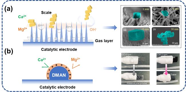
图5 电解海水催化剂阻垢设计:(a) 纳米结构增强氢气泡传质过程,通过氢气泡破裂除垢[35];(b) 引入质子海绵排斥Ca2+、Mg2+[44]

Fig. 5 Scale inhibition design of electrolytic seawater catalyst. (a) The nanostructure enhances the hydrogen bubble mass transfer process and removes scale through the hydrogen bubble rupture[35]. (b) The introduction of proton sponge repels Ca2+ and Mg2+[44].Copyright 2024,Elsevier

表1 高性能HER催化剂阻垢策略测试环境

Table 1 Testing environment for anti-scaling strategies of high-performance HER catalysts

Catalyst Test environment Conditions Ref
HCN-Cu Natural Seawater 4.1 mg/L Ca2+
1054.2 mg/L Mg2+
35
NiCoN|NixP|NiCoN Natural Seawater pH=7.20 43
3D Pt/C Natural Seawater pH=8.10 44
The essence of cathodic alkaline scale formation lies in the drastic pH change near the cathode surface, where large amounts of Ca2+ and Mg2+ combine with OH- at the cathode surface, leading to scale deposition. In addition to the above-mentioned approach of regulating catalyst surface morphology and improving catalysts to optimize their surface microenvironment, this is also an effective method to prevent cathodic alkaline scale deposition. The electrostatic repulsion effect is frequently applied in studies on chlorine corrosion inhibition on the anode side[45-46]. By adding anionic groups such as phosphate, sulfate, and borate to the electrolyte system, Cl- can be effectively prevented from reaching the anode surface and competing with OER[47]. Similarly, utilizing this phenomenon to repel Ca2+ and Mg2+ can partially inhibit the deposition of alkaline scale. Liang et al.[44] fully mixed the organic superbase DMAN with the cathode catalyst, leveraging the electrostatic repulsion effect. DMAN acts as a proton sponge, absorbing and storing large amounts of H+, thereby generating a significant repulsive effect on Ca2+ and Mg2+ in seawater, which partially inhibits the formation of alkaline scale (Figure 5b). However, the anti-scaling effect of this strategy is limited, and alkaline scale still deposits on the cathode surface during long-term seawater electrolysis tests.
Currently, research on seawater electrolysis hydrogen production catalysts still focuses primarily on suppressing chlorine corrosion on the anode side. Most catalysts used in neutral seawater environments can only fully demonstrate their effectiveness at low current densities[48-50]. However, to meet future hydrogen energy demands, developing catalysts that perform well at high current densities is of great significance for future seawater electrolysis hydrogen production. Kasani et al.[51]summarized the overpotentials of several seawater electrolysis catalysts at high current densities of 1000 and 500 mA·cm-2, as shown in Table 2and Figure 6. It is evident that current research on seawater electrolysis catalysts continues to focus on alkaline seawater environments while also progressing toward higher current densities. At high current densities, apart from Pt-Co-Mo, various Ni-based catalysts exhibit excellent performance, suggesting that developing high-performance catalysts based on Ni could be a promising research direction in the field of seawater electrolysis catalysts.
表2 大电流密度下部分海水电解制氢HER催化剂过电位比较[51]

Table 2 Comparison of overpotentials for HER catalysts in partial seawater electrolysis for hydrogen production at high current densities[51]

HER catalyst Electrolyte Overpotential Max current density Ref
NiMoN 1.0 M KOH + seawater 82 mV @100 mA·cm-2
160 mV @500 mA·cm-2
218 mV @1000 mA·cm-2
1000 mA·cm-2 52
Ir-doped Ni/Fe-based MOF arrays on nickel foam 1.0 M KOH + seawater 180 mV @500 mA·cm-2
238 mV @1000 mA·cm-2
1000 mA·cm-2 53
Cu2S@Ni 1.0 M KOH + seawater 200 mV @500 mA·cm-2 500 mA·cm-2 54
Ni-W2N 1.0 M KOH + seawater 265 mV @500 mA·cm-2
310 mV @1000 mA·cm-2
345 mV @1500 mA·cm-2
1500 mA·cm-2 55
Ni-MoN 1.0 M KOH + seawater 29 mV @10 mA·cm-2
66 mV @100 mA·cm-2
128 mV @500 mA·cm-2
500 mA·cm-2 56
Pt-Co-Mo 1.0 M KOH + seawater 25 mV @100 mA·cm-2
74 mV @500 mA·cm-2
117 mV @1000 mA·cm-2
194.1 mV @2000 mA·cm-2
2000 mA·cm-2 57
P-Ni4Mo 1.0 M KOH + seawater 260 mV @100 mA·cm-2
551 mV @1000 mA·cm-2
1000 mA·cm-2 58
B-Ni2P-MoO2 1.0 M KOH + seawater 29 mV @10 mA·cm-2
50 mV @50 mA·cm-2
64 mV @100 mA·cm-2
91 mV @200 mA·cm-2
496 mV @500 mA·cm-2
500 mA·cm-2 59
图6 部分海水电解催化剂在大电流密度下过电位:(a) 1000 mA·cm-2; (b) 500 mA·cm-2[51]

Fig. 6 Some seawater electrolysis catalysts have an overpotential of (a) 1000 mA·cm-2 (b) 500 mA·cm-2 at high current density[51].

4.3 electrode protective layer

As mentioned above, the alkaline scale deposited on the cathode is essentially a precipitate formed by the combination of Ca2+, Mg2+, and OH- from seawater at the electrode surface. In addition to electrode morphology engineering, constructing a protective layer on the cathode surface to prevent the binding of alkaline scale-forming ions can also effectively eliminate the deposition of alkaline scale.
Yi et al[60] constructed a special "hydrophobic-solid" layer on the surface of NiCu alloy. The formation of this layer benefits from the high surface energy of the alloy, which promotes water adsorption. A large number of water molecules adsorb onto the alloy surface, forming a complete hydrogen-bond network and subsequently creating a dense hydrated layer, known as the "hydrophobic-solid" layer, as shown in Figure 7a. The presence of this dense hydrated layer significantly increases the energy barrier for Mg2+ penetration, forcing it to nucleate uniformly in the electrolyte and preventing it from reaching the electrode surface, thereby effectively reducing alkali scale deposition. Accelerated durability test results indicate that the base material Ni experiences voltage rise due to alkali scale deposition on the cathode surface after only 10 minutes of electrolysis in the simulated solution. In contrast, the presence of the "hydrophobic-solid" layer ensures stable catalyst performance over prolonged electrolysis periods, achieving stable operation for thousands of hours at a current density of 100 mA·cm-2, as shown in Table 3. Similarly, to prevent Mg2+ from reaching the cathode surface, Liu et al[61] first verified through quantitative experiments and XRD analysis that the primary ion causing alkali scale deposition is Mg2+ (Figure 7b). To address the deposition issue, they then in situ coated a layer of Ni(OH)2 ion-separating layer on nickel foam (NF). The working mechanism of this separating layer is based on electrostatic repulsion: since the surface of the Ni(OH)2 film carries a positive charge, it effectively blocks the transport of Mg2+ to the cathode surface. Meanwhile, the nanoscale cracks on its surface accelerate the mass transfer of OH- and H2O required for HER, resulting in higher catalytic performance compared to the Ni electrode. The NF electrode modified with this film can reduce precipitation by approximately 98.3% during electrolysis in natural seawater and exhibits operational stability exceeding 100 hours at a current density of 10 mA·cm-2.
表3 电极保护层阻垢策略实际测试环境

Table 3 Practical testing environment for electrode protection layer anti-scaling strategy

Catalyst Test environment Conditions Ref
Pt-NiCu Simulated seawater Composition:0.3 M MgCl2+0.03 M MgSO4+0.06 M CaCl2
Current density:100 mA·cm-2
Stability:1000 h
60
Ni(OH)2@NF Natural Seawater Current density:10 mA·cm-2
Stability:100 h
61
图7 电解海水催化剂保护层阻垢设计:(a)阻垢层作用机理[60-61];(b) 定量实验证明引起碱垢沉积的主要离子为Mg2+[61]

Fig. 7 Scale inhibition design of protective layer of electrolytic seawater catalyst(a) Mechanism of scale inhibition layer[60-61].(b) Quantitative experiments show that Mg2+ is the main ion that causes alkaline scale deposition[61]

As mentioned above, the construction of the electrode protective layer has significantly inhibited alkali scale deposition; however, the protective layer may have some negative impact on the electrode's catalytic performance. For instance, an excessively thick protective layer could increase interfacial mass transfer resistance and reduce the kinetics of the hydrogen evolution reaction. Additionally, an overly dense protective layer might partially cover the active sites on the electrode surface, leading to an increase in overpotential. In practical design, material innovation can be employed to minimize these negative effects of the protective layer, thereby achieving a balance between catalytic performance and anti-deposition capability.

4.4 Local Reaction Condition Regulation in Seawater

From the perspective of managing OH-, the pH in the micro-regions on the electrode surface can be regulated to consume the excess OH- produced on the surface, thereby inhibiting the deposition of alkaline scale. Unlike physical anti-scaling methods such as adjusting the morphology of the catalyst surface or constructing an anti-scaling layer on its surface, regulating the pH in the micro-regions on the cathode surface to neutralize OH- is a chemical process that fundamentally disrupts the necessary conditions for alkaline scale formation. Compared to these other methods, this approach offers more stable operation and significantly superior descaling performance.
The regulation of local pH on the cathode surface is achieved by creating an H+-rich or OH--rich environment near the cathode. Guo et al.[62] captured OH- by introducing a Lewis acid layer on the surface of transition metal oxide catalysts. Due to the strong binding interaction between Lewis acids and OH-, Mg2+ and Ca2+ in seawater would find it difficult to combine with them on the electrode surface to form precipitates (Figure 8a). Meanwhile, thanks to their strong binding with OH-, a strongly alkaline microenvironment is established within the electrical double layer, and even the small amount of dissociated OH- will be neutralized by buffering ions such as HCO3- in seawater, thereby preventing the rapid increase of pH to some extent and inhibiting the deposition of alkaline scale. This inhibition strategy achieved long-term stability for more than 100 hours in untreated natural seawater and demonstrated an industrial-level current density of 1.0 A·cm-2 in a flowing electrolytic cell, confirming its effectiveness in suppressing alkaline scale deposition. Different from the above-mentioned research, Han[15] explored the effect of the porous cathode/bipolar membrane (BPM) interface on slowing down the formation of inorganic precipitates in direct seawater electrolysis systems, proposing an optimized design of the interface between the porous electrode and BPM in zero-gap seawater electrolyzers to mitigate alkaline scale deposition (Figure 8b). Han introduced open areas on the BPM that do not come into contact with the porous cathode, facilitating the diffusion of unreacted free protons and protons generated from water dissociation at the BPM to the cathode surface, thus creating a localized acidic environment at the cathode. This strategy helps further acidify the seawater, slows down the rise of pH on the cathode surface, and inhibits the formation of inorganic precipitates.
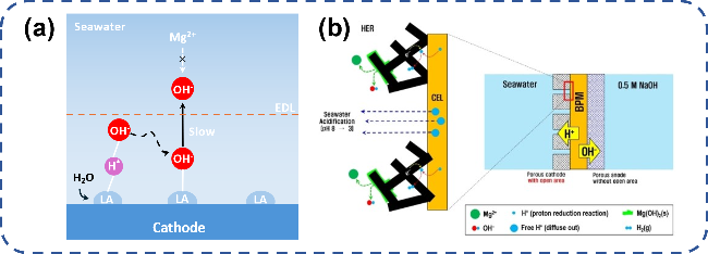
图8 电解海水局部反应条件调控阻垢设计:(a) 路易斯酸层捕捉OH-实现局部碱化[62];(b) 多孔阴极/双极膜界面传输H+实现局部酸化[15]

Fig. 8 Local reaction conditions of electrolytic seawater control scale inhibition design. (a) The Lewis acid layer captures OH- to achieve local alkalization[62].Copyright 2023,Springer Nature; (b) The porous cathode/bipolar membrane interface transmits H+ to achieve local acidification[15].Copyright 2022,John Wiley and Sons

4.5 Polarity Reversal

In the field of hydrogen production via water electrolysis, pulsed electrolysis is often employed to enhance mass transfer at the electrode interface during the electrolysis process. However, due to the presence of numerous impurity ions such as Cl-, Mg2+, and Ca2+ in seawater, pulsed power supply is rarely used for seawater electrolysis. Here, we summarize a novel electrolysis method that achieves pH balance in the electrolytic system by periodically reversing the electrode polarity. This method has been extensively studied in wastewater treatment, and its working principle involves using the H+ generated after polarity reversal to neutralize the OH- produced by the electrode before reversal, thereby achieving in-situ pH regulation, as shown in Figure 9. Zhou et al.[63] applied the concept of polarity reversal electrolysis to water softening, demonstrating through continuous experiments over 20 cycles that periodically reversing electrode polarity can effectively remove hardness ions such as Mg2+ and Ca2+, extending electrode lifespan while reducing energy losses and safety hazards caused by scale deposition on the electrode surface. Similarly, Jin et al.[64] also utilized polarity reversal to remove scale deposits from the electrode surface in situ. The difference is that Jin et al. quantitatively monitored changes in scale deposition on the electrode surface within a single polarity reversal cycle under ultra-high current densities ranging from 100 to 250 A·m-2. The experimental results indicate that this electrolysis method can effectively remove scale deposits, reduce softening energy consumption, and improve operational stability, thus proving the applicability of polarity reversal under high current density conditions.
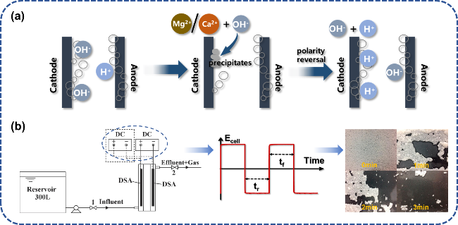
图9 极性互换去除电极表面水垢:(a) 除垢机理示意图;(b) 极性互换电解装置及其在150 A·m-2电流密度下交流电解3 min电极表面水垢沉积变化[64]

Fig. 9 Polarity reversal to remove scale on electrode surface. (a) Schematic diagram of descaling mechanism. (b) Polarity reversal electrolysis device and its change of scale deposition on electrode surface in AC electrolysis for 3 min at 150 A·m-2 current density[64]. Copyright 2019,Elsevier

The aforementioned literature demonstrates the effectiveness of polarity reversal in removing scale, but does not explicitly address its inhibitory effect on alkali deposit formation during seawater electrolysis for hydrogen production. It is undeniable that there are certain similarities between the "alkali deposits" formed on the cathode surface during seawater electrolysis and the "scale" deposited on electrode surfaces during hard water softening. First, in terms of compositional makeup, both primarily consist of Mg(OH)2and Ca(OH)2; second, from a generation mechanism perspective, both "scale" and "alkali deposits" result from the substantial accumulation of OH-, which causes a sharp increase in pH at the electrode surface, thereby inducing the precipitation of Mg2+and Ca2+through combination with OH-. As shown in Figure 10, Yan et al.[65]were the first to apply the concept of polarity reversal to the field of hydrogen production via water electrolysis. They designed a membrane-free electrolytic cell with two independent chambers connected by a Ni2+/Ni3+redox couple, which facilitates chamber connection and gas separation. To ensure the continuous and stable operation of the redox couple, it is necessary to periodically reverse the electrode polarity to achieve the cyclic conversion of Ni2+/Ni3+. Since the electrode material used is Ni-based and exhibits poor resistance to chlorine corrosion, this exploration was conducted entirely under alkaline electrolyte conditions and has not yet been applied to seawater electrolysis. However, this work indirectly highlights the potential of using polarity-reversal electrolysis for hydrogen production via water electrolysis, suggesting that applying this electrolysis method to descaling the cathode in seawater electrolysis represents a promising future research direction. Of course, frequent polarity reversals can disrupt the microstructure of the catalytic layer, leading to the detachment of active sites on the electrode surface and reducing electrode lifespan[6,66]. Therefore, how to mitigate the "damage" caused by such reversals still requires further discussion and research.
图10 极性互换方式应用在水电解制氢设计的特殊电解槽[65]

Fig. 10 Polarity reversal method is used in special electrolytic cell designed for hydrogen production by electrolysis[65]

4.6 Electrolytic Cell and Electrolytic System Design

Traditional electrolyzers such as alkaline water electrolyzers (AWE), PEM water electrolyzers (PEMWE), AEM water electrolyzers (AEMWE), and high-temperature solid oxide electrolyzers (SOEC) have already achieved quite high performance requirements when electrolyzing conventional pure water-based electrolytes[67-69]. However, they remain largely unsuitable for electrolytes containing numerous contaminants and impurities, such as seawater. As mentioned earlier, most current seawater hydrogen production systems operate in an alkaline environment, and thus predominantly utilize traditional AEM electrolyzers. Jin et al.[70] summarized the issues associated with directly applying traditional electrolyzers to seawater electrolysis (Figure 11). In general, traditional electrolyzers or electrolysis systems were not designed with consideration of the negative impacts caused by impurity ions in seawater, leading to problems such as electrode corrosion, electrode material blockage, and membrane fouling during electrolysis. Regarding the issue of cathode or membrane blockage due to alkali scale deposition, this section summarizes three strategies reported so far.
图11 传统电解槽直接应用海水电解制氢的优势及弊端[70]

Fig. 11 The advantages and disadvantages of traditional cell in application of seawater electrolysis to hydrogen production[70]

First, traditional seawater electrolyzers commonly employ a symmetric feed approach to achieve electrolysis efficiency comparable to state-of-the-art electrolyzers. However, this conventional feeding method struggles to cope with the significant corrosion and deposition of Cl-, Ca2+, Mg2+, and other substances in seawater on electrode materials and membranes, and still faces challenges in terms of flexibility in regulating electrolyte composition. In contrast, adopting an asymmetric feed supply can effectively address the issue of alkali scale deposition on electrode or membrane surfaces. Shi et al.[71] designed a pH-asymmetric electrolyzer using a sodium ion exchange membrane as a separator, which prevents the transport of Cl- toward the anode and OH- toward the cathode, thereby effectively alleviating Cl- corrosion and the deposition of Ca2+ and Mg2+ (Figure 12a). Additionally, this electrolyzer circulates NaCl solution or natural seawater in the cathode compartment and NaOH solution in the anode compartment. This pH-asymmetric design reduces the overpotential of the two half-reactions in seawater electrolysis, lowering energy consumption. The circulating flow also accelerates the renewal rate of the double-layer components, mitigating the deposition of Ca2+ and Mg2+. The asymmetric feed approach can also be implemented by circulating electrolytes between the anode and cathode compartments. During electrolysis, large amounts of OH- and H+ inevitably accumulate in the anode and cathode compartments, respectively, resulting in a significant pH gradient between the electrodes, reducing electrolysis efficiency and promoting alkali scale deposition. Kato et al.[72] designed a special seawater electrolysis circulation system based on a traditional PEM electrolyzer, where seawater flowing out of the anode compartment is sent to the cathode compartment for electrolysis. The OH- generated during the HER process at the cathode neutralizes the H+ in the liquid flowing from the anode, thus reducing the pH gradient. Similarly, reducing the pH gradient significantly lowers energy consumption and disrupts the external conditions conducive to alkali scale deposition (pH > 9.5), partially alleviating alkali scale accumulation (Figure 12b). Likewise, Rossi et al.[73] designed a novel PEM electrolyzer that uses vapor feed on the anode side and simulated seawater feed on the cathode side. This unique feeding method reduces the competitive transport of Na+ against H+ across the membrane, enhancing the mass transfer efficiency of H+ within the system and significantly lowering the pH gradient compared to the traditional symmetric feed approach. Badreldin et al.[74] designed a membrane-free electrolyzer that also employs an H+-rich anolyte to alleviate the localized pH increase on the cathode surface (Figure 12c), further demonstrating the feasibility of the asymmetric feed approach in seawater electrolysis.
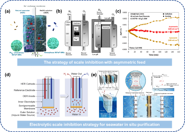
图12 低温海水电解槽阻垢设计:(a) 不对称进料缓解碱垢沉积[71];(b) 改进传统电解液循环路径,将阳极液供给阴极室以降低pH上升[72];(c) 对称/不对称进料方式阴极室pH变化趋势[74];(d) FO技术实现盐水的原位净化电解[75];(e) “液-固-液”相变机制实现海水原位净化电解[77]

Fig. 12 Scale inhibition design of low temperature seawater electrolytic cell. (a) Asymmetric feeding alleviates alkaline scale deposition[71]. (b) The traditional electrolyte circulation path is improved and the anodic solution is fed to the cathode chamber to reduce the pH rise[72]. Copyright 2008,Springer Nature. (c) Trend of pH change in cathode chamber of symmetric/asymmetric feeding mode[74]. Copyright 2024,Elsevier. (d) The “liquid-solid-liquid” phase change mechanism realizes in situ purification and electrolysis of seawater[75]. (e) “Liquid-Solid-Liquid” phase transition mechanism enabling in situ seawater purification via electrolysis[77]. Copyright 2022,Springer Nature

Another strategy to address cathodic alkaline scale deposition is to pre-treat natural seawater to completely isolate Ca2+ and Mg2+ from the electrolysis system. Seawater purification is also a key preliminary step in hydrogen production from seawater, with reverse osmosis (RO) being one of the commonly used membrane processes for seawater purification. However, to overcome the effect of osmotic pressure, this process requires applying high pressure on one side of the membrane, resulting in relatively high energy consumption. In contrast, forward osmosis (FO), a technology with higher energy efficiency, has emerged as a cost-effective alternative for seawater purification prior to electrolysis. Veroneau et al.[75] proposed an electrolyzer design utilizing FO for water electrolysis to produce hydrogen, which can directly use brine without any pretreatment or purification, thereby avoiding the negative impacts and energy waste caused by impurity ions, as shown in Figure 12d. Veroneau's water splitting system consists of an electrochemical compartment separated from the external brine by a semi-permeable membrane. The compartment is filled with a higher-concentration buffer solution at pH=7, which is separated from the external NaCl solution by an acetate cellulose semi-permeable membrane. Under the driving force of the concentration gradient, water molecules continuously transfer into the compartment, thus achieving in-situ purification of the brine. Furthermore, Veroneau et al.[76] replaced the external NaCl solution with untreated natural seawater and demonstrated that when the water splitting rate and forward osmosis rate reach equilibrium, continuous water splitting effectively maintains the concentration gradient, ensuring the sustained in-situ purification of seawater. The FO-based direct seawater electrolysis system for hydrogen production exhibits high flexibility and scalability, making it suitable for large-scale H2 collection from seawater.
Building upon FO-driven seawater purification, Xie et al.[77]introduced another innovation. Their designed electrolysis system uses concentrated KOH as a self-regulating electrolyte (SDE) and hydrophobic porous polytetrafluoroethylene (PTFE) as a semi-permeable membrane. Unlike previous systems, the two sides of the semi-permeable membrane in this setup are no longer a traditional concentrated solution and a dilute solution, but rather a concentrated solution and water vapor (Figure 12e). This design enables the preferential diffusion of water vapor driven by the vapor pressure difference between seawater and the SDE, while completely preventing the penetration of liquid seawater and impurity ions. Specifically, seawater on the seawater side spontaneously vaporizes, and the water vapor diffuses through short gas channels within the membrane to the SDE side, where it is re-liquefied via absorption by the SDE—a "liquid-gas-liquid" phase transition process. This allows for the in-situ generation of pure water from seawater for electrolysis, while the water consumed during electrolysis maintains the interfacial pressure difference. Experimental results demonstrate that this system can stably produce hydrogen from natural seawater and operate continuously for 3200 hours at a current density of 250 mA·cm-2.
In addition to the seawater electrolyzers operating in low-temperature environments mentioned above, high-temperature solid oxide electrolysis cells (SOECs) driven by thermal energy can also be used to alleviate the issue of alkaline scale deposition. In high-temperature SOECs, water evaporates into steam, which is transported to the cathode to produce H2. The generated O2- ions pass through the solid oxide membrane to reach the anode, where O2 is produced[78]. Lim et al.[79] studied the effects of pure water vapor and seawater vapor on hydrogen production by simulating seawater electrolysis with steam. Their research found that the initial performance and degradation rates of pure water vapor and seawater vapor electrolysis were nearly identical. Seawater electrolysis using solid oxide electrolysis cells can stably operate at a current density of 0.8 A·cm-2 for 70 hours. Furthermore, in high-temperature environments, part of the energy required for water splitting to produce hydrogen can be supplied by thermal energy, thus reducing electricity consumption to some extent and providing certain advantages over low-temperature electrolyzers. However, there are still some challenges associated with seawater electrolysis using solid oxide electrolysis cells, such as electrode lifespan and the damaging effects of trace impurities in seawater vapor on the electrolyzer. Liu et al.[80] used SOECs to electrolyze natural seawater, demonstrating that seawater vapor can effectively prevent the deposition of alkaline scale; however, during long-term operation, trace amounts of salt in the vapor can still cause blockage of the intake pipes or the electrolyzer.

5 Conclusion and Outlook

In recent years, with the preliminary establishment and continuous development of hydrogen production-storage-transportation-utilization industrial chains across various regions, the demand for hydrogen has further increased. To address the high cost and geographical limitations of using pure water as an electrolyte in laboratory-scale water electrolysis, seawater electrolysis for hydrogen production will become a popular research area for large-scale hydrogen generation in the future. Direct seawater electrolysis without pretreatment holds promise for reducing the need for water pre-treatment, simplifying the process flow, and further lowering hydrogen production costs. However, current research on hydrogen production from seawater mostly focuses on designing and preparing stable, highly catalytically active electrocatalysts, electrodes, or interfaces, while few studies have addressed the durability challenges posed by impurity metal cations and anions in natural seawater to the electrolysis system.
In summary, this article reviews the methods currently published for inhibiting alkaline scale deposition at the cathode during neutral seawater electrolysis. From a catalyst perspective, catalysts used in direct seawater electrolysis for hydrogen production should possess good mass transfer efficiency, abundant active sites, and excellent stability. The construction of nanostructured materials provides more room for maneuvering to address catalyst lifespan issues. However, challenges remain, including low current density that falls far short of industrial application requirements, as well as high costs due to the presence of precious metal components. At the electrolyzer level, an asymmetric feedwater approach helps further reduce the pH gradient between electrodes, thereby disrupting the external conditions for alkaline scale deposition while effectively lowering electrolysis energy consumption. Additionally, the widespread application of FO technology integrates seawater purification with hydrogen production via electrolysis, significantly simplifying the seawater-to-hydrogen process and enhancing its flexibility. However, the key to this technology lies in the selection of membrane materials, and improving hydrogen production efficiency still depends on further research into membrane technologies. Finally, the polarity-reversal electrolysis method, applied in water environment treatment studies, offers a new research direction for seawater splitting. This method demonstrates outstanding scale removal efficiency under high current densities, but it causes significant damage to electrode materials, and there is currently no direct research indicating how effective it would be when applied to seawater hydrogen production. Further investigation is needed in the future.
In summary, research on hydrogen production via seawater electrolysis is still in its early stages, and there are many issues that need to be addressed before it can be put into practical application. At the same time, based on the problems identified in the above-mentioned studies, this paper provides a prospect for future research on strategies to inhibit alkaline scale deposition at the cathode during seawater electrolysis and offers the following recommendations.
(1) Develop highly stable seawater electrolysis catalysts under high current densities. Although laboratory-scale catalysts have already demonstrated excellent hydrogen production performance, their current densities are far from meeting industrial-scale hydrogen production requirements, and hydrogen production efficiency still needs further improvement to satisfy future hydrogen energy consumption. Moreover, future research on seawater electrolysis catalysts should focus on designing electrode materials with excellent anti-deposition and corrosion resistance properties. By leveraging multidisciplinary crossover techniques, we can optimize the catalyst's microstructure, increase the number of active sites, enhance intrinsic activity and stability, and simplify preparation processes, laying the foundation for large-scale production.
(2) Reducing the costs of catalytic and membrane materials. Electrolysis of seawater for hydrogen production is a relatively low-cost method, but traditional catalysts rely on precious metals such as platinum to deliver performance. Additionally, in practical applications, the material and maintenance costs of the membrane must also be considered, which limits further cost reductions. In the future, it will be necessary to further design and optimize electrode and membrane materials, extend the service life of the electrolysis system, and reduce hydrogen production costs. Meanwhile, machine learning and other methods can be employed to screen materials, avoiding the need for high-throughput experiments.
(3) Establish a laboratory-scale micro-reaction model. Through theoretical calculations and other methods, further explore the reaction pathways of seawater hydrogen production, the transfer paths of microscopic particles, and the structural changes within catalytic materials. Analyze the mechanisms by which electrolyte components in seawater affect the electrolyzer and catalytic materials, as well as the catalytic reaction mechanisms. Clarify the failure processes of electrode materials and electrolyzers, and develop a systematic analysis framework to provide computational theoretical support for seawater electrolysis hydrogen production.
[1]
Khan M A, Zhao H B, Zou W W, Chen Z, Cao W J, Fang J H, Xu J Q, Zhang L, Zhang J J, Wang Y J, Fang B Z, Zhang D, Li A J, Wilkinson D P, Ignaszak A, Hu C G, Xiao Y, Zou Y Q, Dai L M, Tian N, Lu B A, Yang X D, Huang R, Jiang Y X, Zhou Z Y, Sun S G, Yang X F, Li X, Adair K, Zhang H M, Sun X L. Electrochem. Energy Rev, 2019, 2(3): 507.

[2]
Ursua A, Gandia L M, Sanchis P. Proc. IEEE, 2012, 100(3): 811.

[3]
Rajeshwar K, McConnell R, Licht S. Solar Hydrogen Generation. 1st ed. New York: Springer, 2008: 3-4.

[4]
Yi B, Yu H. Chin. J. Eng. Sci, 2018, 20(3): 58.

[5]
Qian S, Li L. Rail. Transp. Econ., 2024, 46(02): 112.

(钱思达, 李雷. 铁道运输与经济, 2024, 46(02): 112..).

[6]
Mazloomi S K, Sulaiman N. Renew. Sustain. Energy Rev., 2012, 16(6): 4257.

[7]
Chi J, Yu H M. Chin. J. Catal., 2018, 39(3): 390.

[8]
Zheng X W, Zhao R, Wu J Z, Wang M L, Chen Y B. Chem. Ind. Eng. Prog., 2015, 41(11): 5800

(郑学文, 赵蕊, 吴家哲, 王朦胧, 陈玉彬. 化工进展, 2015, 41(11): 5800).

[9]
Boudries R. Int. J. Hydrog. Energy, 2013, 38(26): 11507.

[10]
Khan M A, Al-Attas T, Roy S, Rahman M M, Ghaffour N, Thangadurai V, Larter S, Hu J G, Ajayan P M, Kibria M G. Energy Environ. Sci., 2021, 14(9): 4831.

[11]
Bennett J. Int. J. Hydrog. Energy, 1980, 5(4): 401.

[12]
Abdel-Aal H K, Hussein I A. Int. J. Hydrog. Energy, 1993, 18(7): 553.

[13]
Vos J G, Wezendonk T A, Jeremiasse A W, Koper M T M. J. Am. Chem. Soc., 2018, 140(32): 10270.

[14]
Lu X Y, Pan J, Lovell E, Tan T H, Ng Y H, Amal R. Energy Environ. Sci., 2018, 11(7): 1898.

[15]
Han J H. ChemSusChem, 2022, 15(11): e202200372.

[16]
Birss V I, Damjanovic A, Hudson P G. J. Electrochem. Soc., 1986, 133(8): 1621.

[17]
He Z X, Shi C X, Chen Z C, Pan L, Huang Z F, Zhang X W, Zou J J. Chem. Ind. Eng. Prog., 2021, 40(09): 4762.

(何泽兴, 史成香, 陈志超, 潘伦, 黄振峰, 张香文, 邹吉军. 化工进展, 2021, 40(09): 4762.).

[18]
Zeng Z H, Chang K C, Kubal J, Markovic N M, Greeley J. Nat. Energy, 2017, 2(6): 17070.

[19]
Buttler A, Spliethoff H. Renew. Sustain. Energy Rev., 2018, 82: 2440.

[20]
Liu W H, Cao D, Cheng D J. Energy Technol., 2021, 9(2): 2000855.

[21]
Zhang M, de Respinis M, Frei H. Nat. Chem., 2014, 6(4): 362.

[22]
Cheng W R, Zhao X, Su H, Tang F M, Che W, Zhang H, Liu Q H. Nat. Energy, 2019, 4(2): 115.

[23]
Lee J S, Kumar A, Yang T, Liu X H, Jadhav A R, Park G H, Hwang Y, Yu J M, Nguyen C T, Liu Y, Ajmal S, Kim M G, Lee H. Energy Environ. Sci., 2020, 13(12): 5152.

[24]
Khatun S, Hirani H, Roy P. J. Mater. Chem. A, 2021, 9(1): 74.

[25]
Zhu K Y, Zhu X F, Yang W S. Angew. Chem. Int. Ed., 2019, 58(5): 1252.

[26]
Lim A, Ham K, Elrefaei S, Spanos I. Curr. Opin. Electrochem., 2024, 47: 101560.

[27]
Gao F Y, Yu P C, Gao M R. Curr. Opin. Chem. Eng., 2022, 36: 100827.

[28]
Kirk D W, Ledas A E. Int. J. Hydrog. Energy, 1982, 7(12): 925.

[29]
Oh B S, Oh S G, Hwang Y Y, Yu H W, Kang J W, Kim I S. Sci. Total Environ., 2010, 408(23): 5958.

[30]
Auinger M, Katsounaros I, Meier J C, Klemm S O, Biedermann P U, Topalov A A, Rohwerder M, Mayrhofer K J J. Phys. Chem. Chem. Phys., 2011, 13(36): 16384.

[31]
Dionigi F, Reier T, Pawolek Z, Gliech M, Strasser P. ChemSusChem, 2016, 9(9): 962.

[32]
Cuartero M, Crespo G, Cherubini T, Pankratova N, Confalonieri F, Massa F, Tercier-Waeber M L, Abdou M, Schäfer J, Bakker E. Anal. Chem., 2018, 90(7): 4702.

[33]
Zheng W R, Lee L Y S, Wong K Y. Nanoscale, 2021, 13(36): 15177.

[34]
Deslouis C, Festy D, Gil O, Maillot V, Touzain S, Tribollet B. Electrochim. Acta, 2000, 45(11): 1837.

[35]
Kang W D, Meng S Y, Zhao Y C, Xu J Y, Wu S, Zhao K, Chen S, Niu J F, Yu H T, Quan X. Environ. Sci. Technol., 2024, 58(31): 14034.

[36]
Liu D, Yan X X, Guo P F, Yang Y X, He Y F, Liu J, Chen J, Pan H G, Wu R B. ACS Catal., 2023, 13(11): 7698.

[37]
Serpone N. J. Chem. Educ., 1996, 73(11): A277.

[38]
Carré C, Zanibellato A, Jeannin M, Sabot R, Gunkel-Grillon P, Serres A. Environ. Chem. Lett., 2020, 18(4): 1193.

[39]
Liu X F, Wang T X, Chen Y L, Wang J T, Xie W J, Wu R Q, Xu X T, Pang L H, Zhang X G, Lv Y, Wang G Z, Yamauchi Y, Jin T L. Appl. Catal. B Environ., 2023, 333: 122771.

[40]
Silviya R, Vernekar Y, Bhide A, Gupta S, Patel N, Fernandes R. ChemCatChem, 2023, 15(17): e202300635.

[41]
Haq T U, Pasha M, Tong Y F, Mansour S A, Haik Y. Appl. Catal. B Environ., 2022, 301: 120836.

[42]
Chen Z, Liu D Z, Gao Y X, Zhao Y, Xiao W P, Xu G R, Ma T Y, Wu Z X, Wang L. Sci. China Mater., 2022, 65(5): 1217.

[43]
Yu L, Wu L B, Song S W, McElhenny B, Zhang F H, Chen S, Ren Z F. ACS Energy Lett., 2020, 5(8): 2681.

[44]
Liang J, Cai Z W, He X, Luo Y L, Zheng D D, Sun S J, Liu Q, Li L M, Chu W, Alfaifi S, Luo F M, Yao Y C, Tang B, Sun X P. Chem, 2024, 10(10): 3067.

[45]
Tan L, Yu J T, Wang C, Wang H F, Liu X E, Gao H T, Xin L T, Liu D Z, Hou W G, Zhan T R. Adv. Funct. Mater., 2022, 32(29): 2200951.

[46]
Liu W, Yu J G, Sendeku M G, Li T S, Gao W Q, Yang G T, Kuang Y, Sun X M. Angew. Chem. Int. Ed., 2023, 62(40): e202309882.

[47]
Ma T F, Xu W W, Li B R, Chen X, Zhao J J, Wan S S, Jiang K, Zhang S X, Wang Z F, Tian Z Q, Lu Z Y, Chen L. Angew. Chem. Int. Ed., 2021, 60(42): 22740.

[48]
Shiokawa F, Asilah Haji Tajuddin A, Ohto YT, Yu , Fujita T, Tanimoto H, Xi Z Y, Jeong S, Ito Y. Chem. Eng. J., 2024, 479: 147862.

[49]
Wang N, Ou P F, Hung S F, Huang J E, Ozden A, Abed J, Grigioni I, Chen C, Miao R K, Yan Y, Zhang J Q, Wang Z Y, Dorakhan R, Badreldin A, Abdel-Wahab A, Sinton D, Liu Y C, Liang H Y, Sargent E H. Adv. Mater., 2023, 35(16): 2210057.

[50]
Bhardwaj A A, Vos J G, Beatty M E S, Baxter A F, Koper M T M, Yip N Y, Esposito D V. ACS Catal., 2021, 11(3): 1316.

[51]
Kasani A, Maric R, Bonville L, Bliznakov S. ChemElectroChem, 2024, 11(9): e202300743.

[52]
Yu L, Zhu Q, Song S W, McElhenny B, Wang D Z, Wu C Z, Qin Z J, Bao J M, Yu Y, Chen S, Ren Z F. Nat. Commun., 2019, 10: 5106.

[53]
Zhai X J, Yu Q P, Liu G S, Bi J L, Zhang Y, Chi J Q, Lai J P, Yang B, Wang L. J. Mater. Chem. A, 2021, 9(48): 27424.

[54]
Zhang B S, Xu W W, Liu S, Chen X, Ma T F, Wang G H, Lu Z Y, Sun J. J. Power Sources, 2021, 506: 230235.

[55]
Dan Z X, Liang W L, Gong X Y, Lin X Y, Zhang W Q, Le Z C, Xie F Y, Chen J, Yang M Z, Wang N, Jin Y S, Meng H. ACS Mater. Lett., 2022, 4(7): 1374.

[56]
Wu L B, Zhang F H, Song S W, Ning M H, Zhu Q, Zhou J Q, Gao G H, Chen Z Y, Zhou Q C, Xing X X, Tong T, Yao Y, Bao J M, Yu L, Chen S, Ren Z F. Adv. Mater., 2022, 34(21): 2201774.

[57]
Yu W L, Chen Z, Fu Y L, Xiao W P, Ma T Y, Dong B, Chai Y M, Wu Z X, Wang L. Appl. Catal. B Environ., 2022, 317: 121762.

[58]
Li G, Feng S, Li J, Deng P, Tian X, Wang C, Hua Y. Chin. J. Struct. Chem., 2022, 41(7): 2207068.

[59]
Phan L P, Tran T T N, Truong T K, Yu J M, Nguyen H T, Phan T B, Thi Tran N H, Tran N Q. J. Phys. Chem. Lett., 2023, 14(32): 7264.

[60]
Yi L, Chen X, Wen Y J, Chen H C, Zhang S X, Yang H, Li W B, Zhou L H, Xu B B, Xu W W, Guan W B, Dai S, Lu Z Y. Nano Lett., 2024, 24(19): 5920.

[61]
Liu Q F, Yan Z, Gao J X, Fan H F, Li M, Wang E D. Chem. Sci., 2023, 14(42): 11830.

[62]
Guo J X, Zheng Y, Hu Z P, Zheng C Y, Mao J, Du K, Jaroniec M, Qiao S Z, Ling T. Nat. Energy, 2023, 8(3): 264.

[63]
Zhou J, Liu J Y, Rao Y F, Yang L, Jiang B, Yan W, Xu X, Xu H. Desalination, 2023, 568: 117028.

[64]
Jin H C, Yu Y, Zhang L, Yan R X, Chen X M. Sep. Purif. Technol., 2019, 210: 943.

[65]
Yan X Y, Biemolt J, Zhao K, Zhao Y, Cao X J, Yang Y, Wu X Y, Rothenberg G, Yan N. Nat. Commun., 2021, 12: 4143.

[66]
Qiu Y, Song H H, Wang Z H, Han S L. J. Water Process. Eng., 2023, 56: 104419.

[67]
Xie L B, Wang L L, Liu X, Chen J M, Wen X X, Zhao W W, Liu S J, Zhao Q. Nat. Commun., 2024, 15: 5702.

[68]
Rocha F, Georgiadis C, Van Droogenbroek K, Delmelle R, Pinon X, Pyka G, Kerckhofs G, Egert F, Razmjooei F, Ansar S A, Mitsushima S, Proost J. Nat. Commun., 2024, 15: 7444.

[69]
Shimada H, Yamaguchi T, Kishimoto H, Sumi H, Yamaguchi Y, Nomura K, Fujishiro Y. Nat. Commun., 2019, 10: 5432.

[70]
Jin H Y, Xu J, Liu H, Shen H F, Yu H M, Jaroniec M, Zheng Y, Qiao S Z. Sci. Adv., 2023, 9(42): eadi7755.

[71]
Shi H, Wang T Y, Liu J Y, Chen W W, Li S Z, Liang J S, Liu S X, Liu X, Cai Z, Wang C, Su D, Huang Y H, Elbaz L, Li Q. Nat. Commun., 2023, 14: 3934.

[72]
Kato Z, Izumiya K, Kumagai N, Hashimoto K. J. Solid State Electrochem., 2009, 13(2): 219.

[73]
Rossi R, Hall D M, Shi L, Cross N R, Gorski C A, Hickner M A, Logan B E. Energy Environ. Sci., 2021, 14(11): 6041.

[74]
Badreldin A, El Ghenymy A, Al-Zubi A R, Ashour A, Hassan N, Prakash A, Kozusznik M, Esposito D V, Solim S U, Abdel-Wahab A. J. Power Sources, 2024, 593: 233991.

[75]
Veroneau S S, Nocera D G. Proc. Natl. Acad. Sci. U. S. A., 2021, 118(9): e2024855118.

[76]
Veroneau S S, Hartnett A C, Thorarinsdottir A E, Nocera D G. ACS Appl. Energy Mater., 2022, 5(2): 1403.

[77]
Xie H P, Zhao Z Y, Liu T, Wu Y F, Lan C, Jiang W C, Zhu L Y, Wang Y P, Yang D S, Shao Z P. Nature, 2022, 612(7941): 673.

[78]
Laguna-Bercero M A. J. Power Sources, 2012, 203: 4.

[79]
Lim C K, Liu Q L, Zhou J, Sun Q, Chan S H. J. Power Sources, 2017, 342: 79.

[80]
Liu Z, Han B B, Lu Z Y, Guan W B, Li Y Y, Song C J, Chen L, Singhal S C. Appl. Energy, 2021, 300: 117439.

Outlines

/