
The Application of Metal Organic Frameworks in Battery Electrodes
Received date: 2025-03-03
Revised date: 2025-04-28
Online published: 2025-09-01
Supported by
The National Natural Science Foundation of China(51802094)
The Natural Science Foundation of Hunan Province(2024JJ7164)
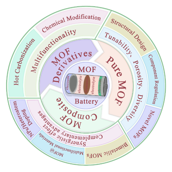
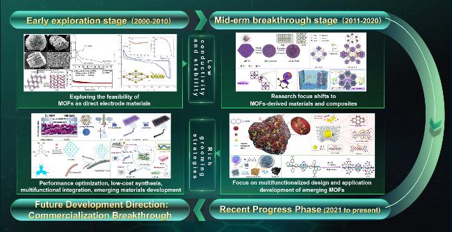
As environmental challenges continue to escalate, the importance of energy storage development has never been greater. The design and advancement of high-performance batteries are now essential to meet the demands of modern society. However, existing battery substrates are inadequate for the production of next-generation batteries. Metal-Organic Frameworks (MOFs) have emerged as a novel class of multifunctional materials that offer significant advantages as battery substrates, including high specific surface area, exceptional porosity, and customizable properties. This review comprehensively examines the applications of various MOF substrates in the field of battery electrodes, and delves into innovative application strategies, challenges and outlines future development prospects for MOF electrode substrates, emphasizing their transformative potential in enhancing electrode performance, paving the way for their integration into sustainable energy solutions.
1 Introduction
2 Pure MOFs electrode material
3 MOFs composite electrode materials
4 MOFs derivatives and their composite electrode materials
5 Conclusion and outlook
Key words: metal-organic framework; battery; electrode; application strategy
Chen Jiayao , Xiao Pengcheng , Nie Saiqun , Luo Fuli , Zhao Tian , Chen Yi . The Application of Metal Organic Frameworks in Battery Electrodes[J]. Progress in Chemistry, 2025 , 37(9) : 1301 -1320 . DOI: 10.7536/PC20250301
表1 纯MOFs电极材料的相关总结Table 1 Relevant summaries of pure MOFs electrode materials |
| Summary of pure MOFs electrode materials | ||
|---|---|---|
| Materials | Advantages | Disadvantages |
| pure MOFs electrode materials | (1) Complete skeleton structure, clear and stable pore structure; (2) Functional groups are intact, and can effectively circumvent losses during optimization; (3) Relatively simple preparation and application process, which is conducive to cost savings. | (1) Pure MOFs electrode materials generally have poor electrical conductivity and insufficient mechanical strength; (2) Although some of the pure MOFs are chemically stable, most of the MOFs have poor environmental stability; (3) Mass production remains a challenge due to performance and cost constraints. |
| Optimization strategy of pure MOFs electrode materials and their characteristics | ||
| Optimization strategy | Advantages | Disadvantages |
| Adjustment component (functional ligand or metal ion) | Selection of functional components to improve the insulating properties of MOFs, as well as optimization of their electron-leaping modes and enhancement of charge carrier concentration | Most functional ligands are expensive and the commissioning phase is cumbersome and time-consuming |
| Adjustment of synthesis conditions (time, temperature, amount of solvent, etc.) | Adjust the preparation conditions to achieve MOF design with different shapes, particle sizes, and structures, in order to selectively adjust the active sites and mechanism of action of MOF electrode materials | Difficult to achieve precise control of morphology, requiring extensive system experiments and characterization tests |
| Preparation of novel conductive MOFs | The research and development of new high-performance MOFs can effectively circumvent the shortcomings of traditional MOFs and realize the upgrading of the application of MOFs in the field of battery electrodes. | The development process is difficult and time-consuming and requires a very solid experimental foundation |
表2 MOFs复合电极材料的相关总结Table 2 Relevant summaries of MOFs composite electrode materials |
| Summary of MOFs composite electrode materials | ||
|---|---|---|
| Materials | Advantages | Disadvantages |
| MOFs composite electrode materials | (1) Maximization of advantages: Components can form complementary performance, structural advantages, to achieve the optimization of specific functions; (2) Performance optimization: on the basis of maintaining the original structure of MOFs, realize the simultaneous improvement of conductivity and stability of MOFs-based electrode materials. | (1) Complex synthesis process: the preparation process of MOFs composite electrode materials involves the combination and interaction of multiple materials, high requirements for equipment and operation, so it increases the cost and difficulty of production; (2) Interfacial contact problem: Due to the differences in electronegativity and potential between materials, the homogeneity of the contact interface is more difficult to control, so it may lead to an increase in interfacial resistance, which affects the efficiency of charge and ion transmission. (3) Complexity of performance prediction: Due to the complexity of the composition and structure of the composite electrode material, its electrochemical performance is difficult to accurately predict, and the performance of the same product may vary from batch to batch, which hinders its large-scale application to a certain extent. |
| Optimization strategy of MOFs composite electrode materials and their characteristics | ||
| Optimization strategy | Advantages | Disadvantages |
| Composite with conductive polymers | Can effectively provide abundant functional atoms and mitigate the volume expansion of MOFs-based electrode materials | The interaction mechanism between components needs to be explored; the control of polymer loading level and loading uniformity in composites still needs to be further explored |
| Composite with 2D inorganic conducting materials (RGO, CNT, MXene) | Due to the excellent toughness and conductivity, the composite with MOFs can significantly improve the electrochemical performance of composite electrode materials; the formation of a compact conductive network structure can effectively improve the brittleness, self-stacking and volume expansion phenomena of MOFs. | Due to the differences in the chemical properties of the components, the composite process is prone to agglomeration and sedimentation phenomena; due to the higher cost of conductive materials, the cost of composite materials will be synchronized with the increase in costs. |
| Preparation of bimetallic MOFs by introducing additional metal ions | The synergistic effect of multi-metal can effectively increase the number of active sites in the electrode materials, and at the same time change the electronic structure of MOFs to increase their electron delocalization and charge transfer ability; construct new conductive pathways to enhance the conductivity of the materials. | Prone to structural reorganization and changes, resulting in pore collapse, ligand deletion and misalignment of MOFs. |
| Doped NPs or metal compounds | NPs and metal compounds are rich in active sites, which can provide additional paths for electron transport; they can form new chemical bonds with the metal nodes and ligands of MOFs, which in turn significantly improves the stability of MOFs-based composites. | Most NPs and metal chemistries are expensive. |
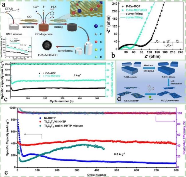
图2 (a) F-Co-MOF/rGO的制备示意图;(a)中的插图是F-Co-MOF/rGO和F-Co-MOF电极的倍率能力;(b) F-Co-MOF/rGO和F-Co-MOF电极在2 A·g-1下的循环稳定性图;(c) F-Co-MOF/rGO和F-Co-MOF电极的奈奎斯特图[65];(d) Ti3C2TX/Ni-HHTP复合材料的制备示意图;(e) 电池在0.5 A·g-1下使用三种不同负极材料的长期循环性能图[68]Fig.2 (a) is a schematic diagram of the preparation of F-Co-MOF/rGO, and the insets in (a) shows the rate capability of F-Co-MOF/rGO and F-Co-MOF electrodes. (b) The cycling stability of F-Co MOF/rGO and F-Co MOF electrodes at 2 A·g-1. (c) Nyquist plots of F-Co-MOF/rGO and F-Co-MOF electrodes[65]. Copyright 2020 Elsevier. (d) Schematic diagram of preparation of Ti3C2TX/Ni HHTP composite material. (e) Long term cycling performance of batteries using three different negative electrode materials at 0.5 A·g-1[68]. Copyright 2024 Elsevier |
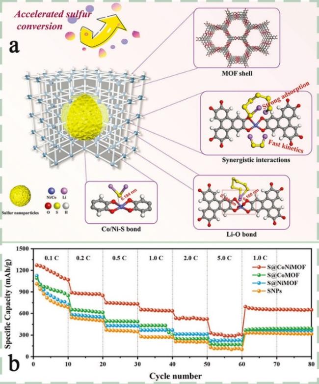
图3 (a) 示意图展示了硫纳米颗粒的“网中鱼”封装效果以及所获得的纳米复合材料中多种相互作用的效果,包括物理限制、共价键和配位键;(b) 展示了具有各种电极的Li-S电池的倍率能力[74]Fig. 3 (a) Illustrates the "fish in the net" encapsulation effect of sulfur nanoparticles and the effects of various interactions in the obtained nanocomposites, including physical confinement, covalent bonds, and coordination bonds. (b) The rate capability of Li-S batteries with various electrodes was demonstrated[74]. Copyright 2023 Wiley VCH GmbH |
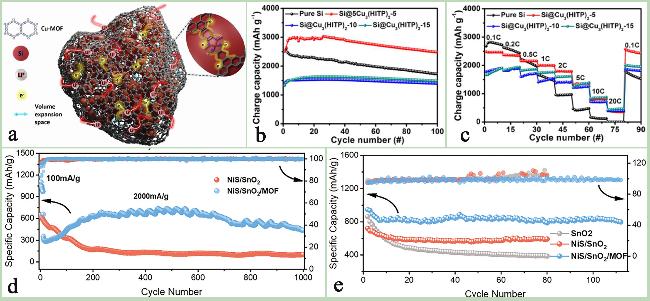
图4 (a) Si@Cu3(HITP)2复合电极材料的工作机理图;(b)纯Si、Si@Cu3(HITP)2-5、Si@Cu3(HITP)2-10和Si@Cu3(HITP)2-15电极的循环性能图:在0.1 C倍率下进行100次充放电循环;(c) 纯Si、Si@Cu3(HITP)2-5、Si@Cu3(HITP)2-10和Si@Cu3(HITP)2-15电极的倍率性能[85];(d) NiS/SnO2、NiS/SnO2/MOF电极在2 A·g-1下的长期循环性能图;(e) SnO2、NiS/SnO2、NiS/SnO2/MOF电极在0.2 A·g-1下的循环性能图[87]Fig. 4 (a) Si@Cu3(HITP)2 working model effect diagram. (b) Cyclability of the pure Si, Si@Cu3(HITP)2-5, Si@Cu3(HITP)2-10, and Si@Cu3(HITP)2-15 electrodes: at a rate of 0.1 C during 100 discharge/charge cycles. (c) Rate capability of the pure Si, Si@Cu3(HITP)2-5, Si@Cu3(HITP)2-10, and Si@Cu3(HITP)2-15 electrodes[85]. Reproduced with permission. (d) Long term cycling performance of NiS/SnO2 and NiS/SnO2/MOF electrodes at 2 A·g-1. (e) The cycling performance of SnO2, NiS/SnO2, and NiS/SnO2/MOF electrodes at 0.2 A·g-1[87]. Copyright 2023 Wiley VCH GmbH |
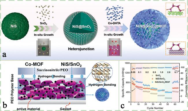
图5 (a)NSM复合材料合成路线示意图;(b) 柔性电极内部结构示意图;(c) SnO2、NiS/SnO2、NiS/SnO2/MOF 电极的倍率性能图[87]Fig.5 (a) Schematic diagram of the synthesis route of NSM composite materials. (b) Schematic diagram of the internal structure of flexible electrodes. (c) Rate performance graphs of SnO2, NiS/SnO2, and NiS/SnO2/MOF electrodes[87]. Copyright 2023 Wiley VCH GmbH |
表3 MOFs衍生物及其复合电极材料的相关总结Table 3 Relevant summaries of MOFs derivatives and their composite electrode materials |
| Summary of MOFs derivatives and their composite electrode materials | ||
|---|---|---|
| Materials | Advantages | Disadvantages |
| MOFs derivatives and their composite electrode materials | (1)Significant improvement of electrical conductivity: Changing the properties of MOFs by physical carbonization or chemical modification can significantly improve their electrical conductivity on the basis of inheriting the high specific surface area and high porosity of pure MOFs; (2)Functional diversification: the diverse classification of MOFs derivatives and rich modification strategies make MOFs-based electrode materials have significant advantages in functional orientation. | (1)Complex synthesis process: The preparation process involves the combination and interaction of multiple materials, requiring precise control of the synthesis conditions, which increases the difficulty and cost of production; (2)Difficult to control the performance of derived materials: After high-temperature pyrolysis or chemical modification, there will inevitably be loss or destruction of the skeleton and functional groups of MOFs, and the effect of such loss on the performance is difficult to control.; (3) Complicated material mechanism: Due to the multi-component and multi-mechanism synergistic effect of MOFs derivatives electrode materials, their mechanism of action is relatively complicated, and it is time-consuming and laborious to analyze and explore the materials with a large number of characterizations. |
| Optimization strategy of MOFs derivatives and their composite electrode materials and their characteristics | ||
| Optimization strategy | Advantages | Disadvantages |
| Physical carbonization | Formation of metal nanoparticles active sites and carbonized skeleton to improve the conductivity and flexibility of MOFs electrode materials; Carbonization products are rich and adjustable in function and structure, and the high-temperature derivatives obtained under different carbonization conditions have different structures and functions. | High-temperature pyrolysis may lead to the collapse of the structure of MOFs, resulting in a decrease in their porosity and specific surface area; energy consumption is also high due to higher equipment requirements |
| Co-pyrolysis after introduction of functional materials or active elements (S, P, N, etc.) | The carbon skeleton network formed with abundant active components can effectively enhance the surface polarity and electrical conductivity of MOFs-based electrode materials; the diverse tunability of this strategy provides more possibilities for the optimization of the performance of MOFs-based electrode materials | Significantly higher production costs due to the synergy of multiple strategies; relatively more difficult to explore the main mechanism of action of hybridized materials |
| Chemical modification (functionalization, ion exchange, etc.) | Functional groups or ions can be introduced in a targeted manner to regulate the force between MOFs and specific conductive ions, improve the concentration of specific ions in the material, and thus enhance the electrochemical performance of MOFs-based electrode materials | The introduction of specific functional groups may require expensive precursors and catalysts, which may increase the preparation cost of MOF-based electrode materials; how to control the influence of the lifetime of functional groups on the long-term stability of electrode materials is a difficult point to realize industrialization; Chemical modification is relatively harmful to the environment |
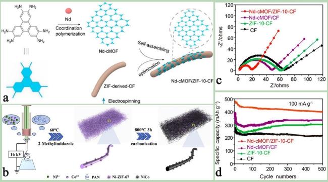
图7 (a) Nd-Cmof在ZIF-10 CF表面上的自组装示意图[96];(b) NiCo-PCNF的制备过程示意图[105];(c) 各电极材料的阻抗图和(d) 循环稳定性图像,Nd-cMOF/ZIF-10-CF(红色)、Nd-cMOF/CF(紫色)、ZIF-10-CF(绿色)和 CF(黑色)[96]Fig.7 (a) Schematic diagram of self-assembly of Nd CMOF on ZIF-10 CF surface[96]. (b) Schematic diagram of the preparation process of NiCo PCNF[105]. Copyright 2024 Elsevier B.V. (c) Impedance maps and (d) cycling stability images of each electrode material, including Nd cMOF/ZIF-10-CF (red), Nd cMOF/CF (purple), ZIF-10-CF (green), and CF (black)[96]. Copyright 2023 American Chemical Society |
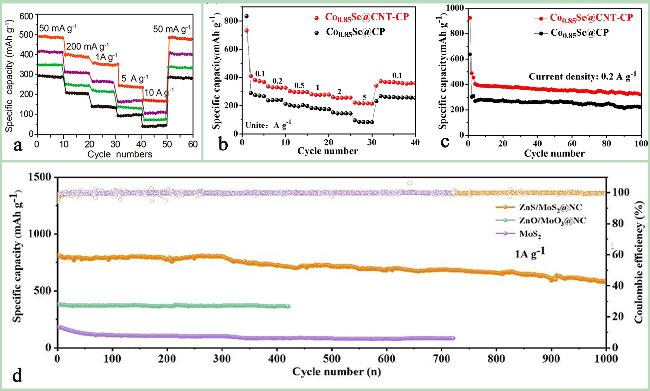
图8 (a) Nd-cMOF/ZIF-10-CF(红色)、Nd-cMOF/CF(紫色)、ZIF-10-CF(绿色)和CF(黑色)的倍率能力比较图[96];(b) Co0.85Se@CNT-CP和Co0.85Se@CP的倍率性能对比图;(c) Co0.85Se@CNT-CP和Co0.85Se@CP在0.2 A·g-1下的循环性能对比图[106];(d) ZnS/MoS2@NC、ZnO/MoO3@NC和MoS2在1 A·g-1下的循环性能[112]Fig.8 (a) Rate capabilities of Nd-cMOF/ZIF-10-CF (red), Nd-cMOF/CF (purple), ZIF-10-CF (green), and CF (black)[96]. Copyright 2023 American Chemical Society. (b) Rate capability of Co0.85Se@CNT-CP and Co0.85Se@CP under different current densities. (c) Comparison of cycle performances of Co0.85Se@CNT-CP and Co0.85Se@CP at 0.2 A·g-1[106]. Copyright 2022 Elsevier Ltd. (d) The cycling performance at 1 A·g-1 of ZnS/MoS2@NC、ZnO/ MoO3@NC and MoS2[112]. Copyright 2024 Wiley VCH GmbH |
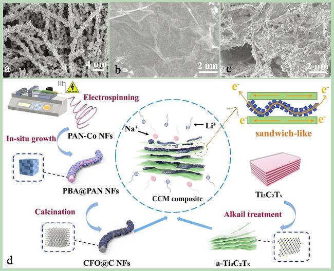
图9 (a) CFO@C NFs的SEM图像;(b) Ti3C2TX的SEM图像;(c) CCM2的SEM照片;(d) MXene (CCM)复合材料CoFe2O4@CNF@MXene多褶夹层状结构的制备示意图[107]Fig. 9 (a) SEM images of CFO@C NFs. (b) SEM image of Ti3C2TX. (c) SEM image of CCM2. (d) Schematic diagram of the preparation of MXene (CCM) composite material CoFe2O4@CNF@MXene with pleated sandwich structure[107]. Copyright 2023 Wiley VCH GmbH |
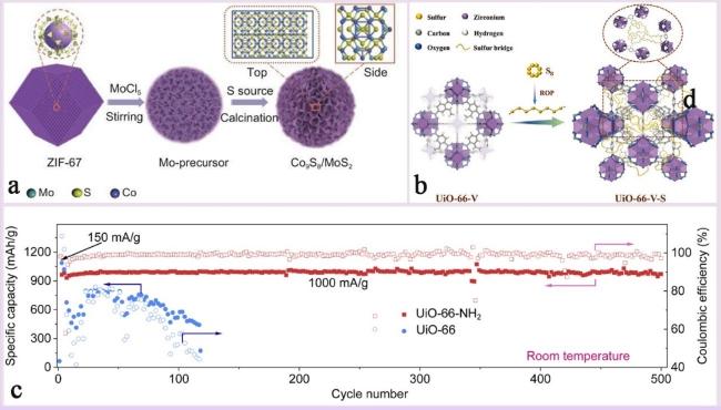
图10 (a) 花状Co9S8/MoS2/C异质球的示意图[113];(b) UiO-66-V-S合成路线示意图[124];(c) 使用Li-Cl2@MOF电极的电池在1000 mA·g-1电流密度下的循环性能[123]Fig.10 (a) Schematic diagram of flower-shaped Co9S8/MoS2/C heterospheres[113]. Copyright 2023 Institute of Coal Chemistry, Chinese Academy of Sciences. (b) Schematic diagram of UiO-66-V-S synthesis route[124]. Copyright 2022 Wiley VCH GmbH. (c) Cycle performance graph of the Li-Cl2@MOF electrods battery at a current density of 1000 mA·g-1[123]. Copyright 2023 Elsevier Inc |
表4 近年来MOF基电池电极材料的电化学性能总结Table 4 Summary of electrochemical properties of MOF-based battery electrode materials in recent years |
| Strategy | Material | Application | Storage capacity CDa)/SCb) (mA·g-1/mAh·g-1) | Cyclic stability CDc)/CNd)/CR e) (mA·g-1/*/mAh·g-1) | Ref |
|---|---|---|---|---|---|
| Pure MOF | Ni3(HITP)2 | LIB | - | 1000/200/128 | 40 |
| Ni-DBH | LIB | 0.1 C/676.19 | 0.2 C/500/70% | 47 | |
| TCPP(Co)-Fe | LIB | 200/2180.4 | 2000/150/220.73 | 43 | |
| Co-MOF-BA0.1 | Li-O2 | 100/14,011 | 1000/215/- | 29 | |
| MIL-100(V) | ZIB | 200/362 | 200/3500/95.45% | 56 | |
| Cu-BTA-H | ZIB | 200/330 | 2000/500/106.1 | 51 | |
| 2D Mn-MOF | ZIB | 3000/104.7 | 4000/1000/119.5% | 57 | |
| S@MOF-525(Cu) | LSB | 5 C/400 | 1 C/200/742 | 44 | |
| MIL-88A@S | LSB | 0.1 C/600 | 0.5 C/1000/200 | 125 | |
| S@Mn-CCs | LSB | 0.2 C/1420 | 0.2 C/200/990 | 126 | |
| Co-HITP | SIB | 200/2019.1 | 8000/15000/192 | 41 | |
| Ca-BDC | SIB | 200/235.2 | 200/100/144 | 127 | |
| Bi-MOF | KIB | 100/419 | 500/1200/315 | 50 | |
| HAN-Cu-MOF | KIB | 2000/161 | 1000/1600/96.7% | 128 | |
| MOF composite | Si@Cu3(HITP)2 | LIB | 0.1 C/2511 | 1 C/1000/1039 | 85 |
| MOF-Fe2O3@carbon@MXene | LIB | 10000/202 | 2000/2000/401 | 129 | |
| Co4-Ir MOF | LIB | 1000/1202 | 500/200/623 | 76 | |
| Co-MOF-CNT | LIB | 100/2486 | 100/100/1451 | 69 | |
| Amorphous CoNi MOF(ACNZ) | LIB | 100/1649.6 | 1000/600/1086.2 | 79 | |
| Ti3C2TX/Ni-HHTP | LIB | 500/424.4 | 500/800/390.2 | 68 | |
| Cu-HHTP/G | LIB | 100/1055 | 1 C/500/621 | 19 | |
| F-Co-MOF | LIB | 100/1202 | 2000/550/771.5 | 65 | |
| MXene@Sn-MOF | LIB | 100/1002 | 2000/500/540 | 130 | |
| Co1.5Ni1.5(HHTP)2@MXene | LIB | - | 4000/5000/70.2 | 131 | |
| Al/Cu-MOF-S | LSB | 0.1C/974.2 | 0.5 C/400/324.4 | 72 | |
| ZnCo-MOF/S | LSB | 0.1 C/1076 | 0.5 C/300/688 | 73 | |
| S@CoNiMOF | LSB | 0.1 C/1258 | 0.2 C/400/690 | 74 | |
| CNTs@ZIF-8 | LSB | 1 C/550 | 1 C/300/85% | 66 | |
| Ce-MOF-808@S/PPy | LSB | 0.1 C/1612.5 | 2 C/200/470 | 60 | |
| Cu-HHTP/MX | ZIB | 4000/173.1 | 4000/1000/166.9 | 132 | |
| Sb@Ni3(HHTP)2 | KIB | 100/590 | 1000/300/431 | 86 | |
| Cu-HHTP/G | KIB | 100/218 | 1C/500/165 | 19 | |
| F-Co-MOF | SIB | 100/428.6 | 100/100/181.6 | 65 | |
| CoFe-ZIF | SIB | 1000/270.6 | 100/500/410.32 | 78 | |
| MOF derivatives | ZnO-C@SiOC | LIB | 100/1364.6 | 800/1000/472 | 133 |
| Ni-NiO-MoO2/rGO | LIB | 500/1233 | 500/220/910 | 89 | |
| Si@NC-ZIF | LIB | 200/2858.32 | 500/200/1034.19 | 119 | |
| NiCo2S4 @HPCS/CNTs e | LIB | 40000/584.9 | 1000/800/782.4 | 88 | |
| SnS2/C/CNT | LIB | 200/1689.7 | 200/100/954.2 | 92 | |
| KL-Si@C-ZIF/N/Co | LIB | 100/2755.9 | 2000/350/981 | 90 | |
| Ni-NiO-MoO2/rGO | LIB | 3000/534 | 1000/400/386 | 89 | |
| Si/pCNF@C | LIB | 1000/1114 | 1000/400/740 | 102 | |
| 3DZCN-C | LSB | 0.5 C/975.6 | 2 C/1000/627.1 | 117 | |
| ZIF-8(C)@CMK-3@S | LSB | 0.1 C/1597.2 | 2 C/300/596 | 134 | |
| S@NiCoP4O12 | LSB | 5 C/518.7 | 1 C/1500/808.26 | 118 | |
| NiCo-PCNF | LSB | 0.2 C/1431.7 | 0.2 C/500/628.5 | 105 | |
| Cu-Mo@NPCN/6.5S | LSB | 2 C/702 | 0.2 C/100/935 | 104 | |
| NixSy-C/CNT@S | LSB | 0.2 C/1468 | 0.5 C/500/76.20% | 135 | |
| α-Mn2O3(Mn-MOF) | ZIB | 50/225 | 20000/1700/92.7 | 136 | |
| T-HVO | ZIB | 30000/217.7 | 30000/3000/215.4 | 99 | |
| VO2(B)@Ta4C3 | ZIB | 500/221.8 | 500/1200/199 | 108 | |
| M9/I2(Zn-MOF) | AZIB | 20000/161.9 | 2000/10000//161.9 | 122 | |
| CaC8H4O4/rGO-450 | KIB | 20/202 | 100/700/110 | 100 | |
| Sn3(PO4)2@PC-48 | KIB | 100/325 | 5000/10000/144 | 93 | |
| CHS-FeS2 | SIB | 20000/224 | 500/100/546.5 | 47 | |
| NOCNTF-15(ZIF-67) | SIB | 10000/185 | 10000/20000/39 | 95 | |
| Nd-cMOF/ZIF-10CF | SIB | 50/480.5 | 100/500/409 | 96 | |
| NOCNTF-15(ZIF-67) | SIB | 10000/185 | 10000/20000/39 | 95 | |
| Fe2O3@C@N-Ti3C2Tx | SIB | 5000/135 | 2000/3000/209 | 137 |
a) current density; b) specific capacity; c) current density; d) cycle number; e) capacity retention. |
| [1] |
|
| [2] |
|
| [3] |
|
| [4] |
|
| [5] |
|
| [6] |
|
| [7] |
|
| [8] |
|
| [9] |
|
| [10] |
|
| [11] |
|
| [12] |
|
| [13] |
|
| [14] |
|
| [15] |
|
| [16] |
|
| [17] |
|
| [18] |
|
| [19] |
|
| [20] |
|
| [21] |
|
| [22] |
|
| [23] |
|
| [24] |
|
| [25] |
|
| [26] |
|
| [27] |
|
| [28] |
|
| [29] |
|
| [30] |
|
| [31] |
|
| [32] |
|
| [33] |
|
| [34] |
|
| [35] |
|
| [36] |
|
| [37] |
|
| [38] |
|
| [39] |
|
| [40] |
|
| [41] |
|
| [42] |
|
| [43] |
|
| [44] |
|
| [45] |
|
| [46] |
|
| [47] |
|
| [48] |
|
| [49] |
|
| [50] |
|
| [51] |
|
| [52] |
|
| [53] |
|
| [54] |
|
| [55] |
|
| [56] |
|
| [57] |
|
| [58] |
|
| [59] |
|
| [60] |
|
| [61] |
|
| [62] |
|
| [63] |
|
| [64] |
|
| [65] |
|
| [66] |
|
| [67] |
|
| [68] |
|
| [69] |
|
| [70] |
|
| [71] |
|
| [72] |
|
| [73] |
|
| [74] |
|
| [75] |
|
| [76] |
|
| [77] |
|
| [78] |
|
| [79] |
|
| [80] |
|
| [81] |
|
| [82] |
|
| [83] |
|
| [84] |
|
| [85] |
|
| [86] |
|
| [87] |
|
| [88] |
|
| [89] |
|
| [90] |
|
| [91] |
|
| [92] |
|
| [93] |
|
| [94] |
|
| [95] |
|
| [96] |
|
| [97] |
|
| [98] |
|
| [99] |
|
| [100] |
|
| [101] |
|
| [102] |
|
| [103] |
|
| [104] |
|
| [105] |
|
| [106] |
|
| [107] |
|
| [108] |
|
| [109] |
|
| [110] |
|
| [111] |
|
| [112] |
|
| [113] |
|
| [114] |
|
| [115] |
|
| [116] |
|
| [117] |
|
| [118] |
|
| [119] |
|
| [120] |
|
| [121] |
|
| [122] |
|
| [123] |
|
| [124] |
|
| [125] |
|
| [126] |
|
| [127] |
|
| [128] |
|
| [129] |
|
| [130] |
|
| [131] |
|
| [132] |
|
| [133] |
|
| [134] |
|
| [135] |
|
| [136] |
|
| [137] |
|
/
| 〈 |
|
〉 |