
Porous Electromagnetic Wave Absorbing Materials
Received date: 2022-09-07
Revised date: 2022-12-19
Online published: 2023-02-20
Supported by
National Natural Science Foundation of China(52072274)
National Natural Science Foundation of China(52272021)
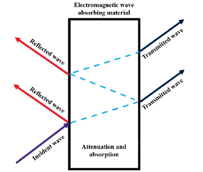
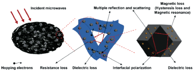
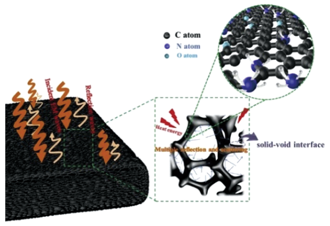
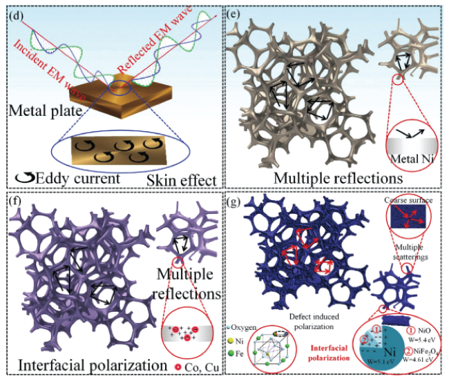
Recently, structure modification has been used more and more widely in enhancing the performance of electromagnetic wave absorbing materials. Porous structure is not only conducive for the incidence of electromagnetic waves into the interior of the material, but also can effectively improve the impedance matching between electromagnetic wave and materials, resulting in enhanced absorption of electromagnetic waves. Additionally, multiple scattering and reflection endowed by the different scale pores in materials extend the propagation path of electromagnetic wave, and further increase its loss. Meanwhile, the lightweight nature of porous material provides a feasible way for the application of some absorbing materials with high performance but unduly density. In this paper, the research status and problem of zero- and three-dimensional porous electromagnetic wave absorbing materials (PEMAM) are summarized and the possible research hotspots and development directions of porous electromagnetic wave absorbing materials in the future are also proposed.

Yang Guodong , Yuan Gaoqian , Zhang Jingzhe , Wu Jinbo , Li Faliang , Zhang Haijun . Porous Electromagnetic Wave Absorbing Materials[J]. Progress in Chemistry, 2023 , 35(3) : 445 -457 . DOI: 10.7536/PC220905
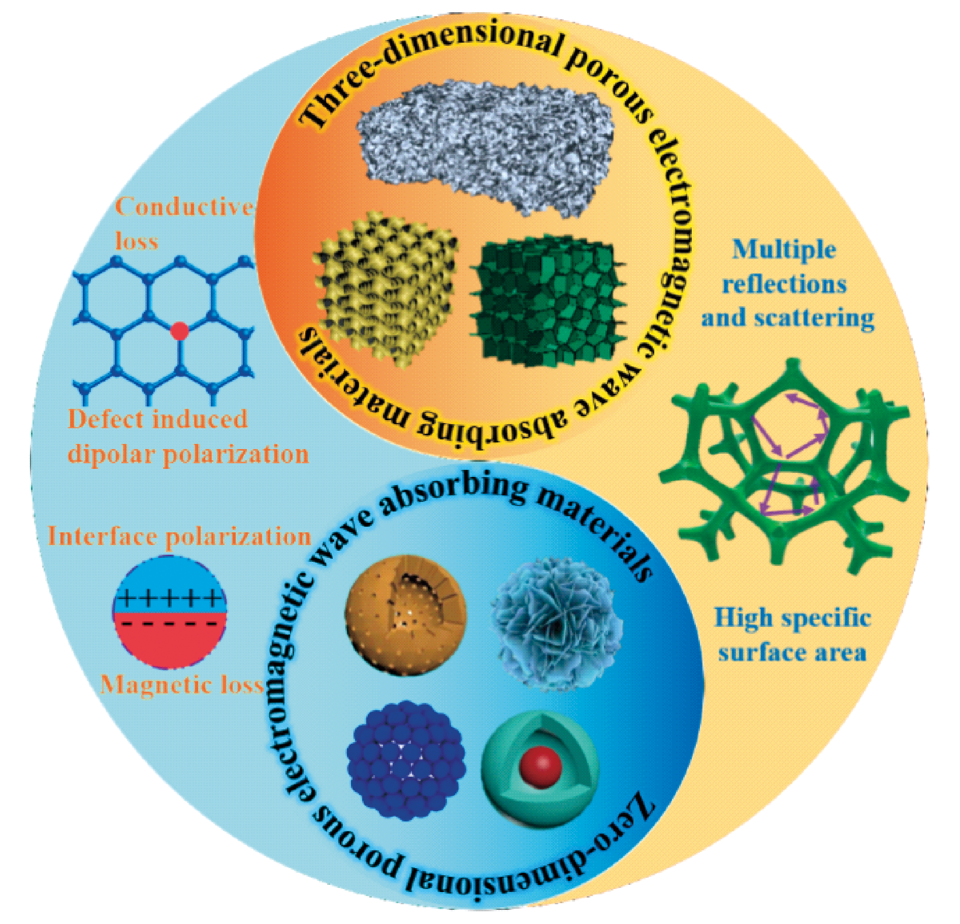
表1 常见零维多孔电磁波吸收材料的制备方法与性能Table 1 Preparation and properties of zero-dimensional porous absorbing materials |
| Materials | Synthesis method | Structure | Frequency (GHz) | Reflection loss (dB) | Thickness (mm) | Effective bandwidth (GHz) | ref |
|---|---|---|---|---|---|---|---|
| FeNi | Precipitation and thermal decomposition | Porous particle | 6.82 | -52.58 | 2 | 2.57 | 15 |
| Carbon/CoNi | Pyrolysis | Porous polyhedrons | 10.8 | -52 | 3 | 6.2 | 16 |
| Bi0.9La0.1FeO3 | Molten salt method and acid corrosion method | Flower-like | 6.9 | -57.9 | 2.9 | 2.7 | 40 |
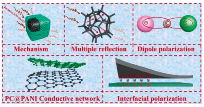
| C@PANI | Roasting and coating process | 3D porous structure | 12.6 | -72.16 | 2.6 | 6.64 | 41 |
| Ni/C | Solvothermal method and carbon reduction | Porous microspheres | 2.6 | -44.5 | 9.5 | 8.2 | 42 |
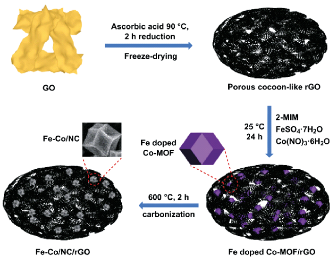
| FeCo/NC/rGO | Freeze drying | Hierarchically porous structure | 11.28 | -43.26 | 2.5 | 9.12 | 43 |
| Fe3O4@C | Situ polymerization and carbonization | Core-shell | 4.8 | -36 | 5 | 3.7 | 44 |
| rGO | Freeze-drying | Cocoon-like | 15.96 | -29.05 | 2 | 5.27 | 45 |
| rGO/MXene/Fe3O4 | Ultrasonic spray technology | Pleated porous microsphere | 11.1 | -51.2 | 2.9 | 6.5 | 46 |
| MnO/Co/C | Hydrothermal and carbonization | Porous microspheres | 11.92 | -68.89 | 2.6 | 5.3 | 47 |
| CNT/pyrolytic carbon | In-situ growth | Hollow microspheres | 12.2 | -56 | 2.3 | 4 | 48 |
| N-Co/C | Solvothermal and carbonization | Porous bowl-like | 13.3 | -42.3 | 1.9 | 5.1 | 49 |
| C/S | Hydrogen peroxide etching and high temperature vulcanization | Hollow porous microspheres | 11.2 | -27.2 | 2.45 | 6.72 | 50 |
表2 常见三维多孔电磁波吸收材料的制备方法与性能Table 2 Preparation and properties of three-dimensional porous absorbing materials |
| Materials | Synthesis method | Structure | Frequency (GHz) | Reflection loss (dB) | Thickness (mm) | Effective bandwidth (GHz) | ref |
|---|---|---|---|---|---|---|---|
| NiO/NiFe2O4/Ni | Leaven dough route | Foam | 16.9 | -50 | 2.1 | 14.24 | 35 |
| Graphene | Freeze drying and solvothermal | Foam | 34.4 | -33.2 | 1 | 60.5 | 38 |
| rGO/α-Fe2O3 | Hydrothermal method | Foam | 7.12 | -33.5 | 5 | 6.4 | 64 |
| Fe3O4/C | Solvothermal approach and carbon reduction | Flower and porous sheet | 5.7 | -54.6 | 4.27 | 6 | 65 |
| MWCNT/graphene | Solvothermal | Foam | 11.6 | -39.5 | — | 12 | 66 |
| MWCNT/WPU | Freeze-drying | Foam | — | -50.5 | 2.3 | 4 | 67 |
| CNT/graphene | Chemical vapor deposition | Foam | — | -47.5 | 1.6 | 4 | 68 |
| Carbon | Hydrothermal and pyrolysis process | Foam | 15.8 | -52.6 | 2.6 | 8.6 | 69 |
| Graphene/carbon fibers | Dip-coating | Aerogel | 14.6 | -30.53 | 1.5 | 4.1 | 70 |
| Carbon/Ni | Alkaline activation process | Hierarchically porous | 4.3 | -47 | 1.75 | 13.5 | 71 |
| rGO/Ti3C2Tx | Self-assembly | Hollow core-shell/foam | 8.8 | -22 | 3.6 | 4 | 72 |
| Al2O3/SiC | 3D printing and chemical vapor infiltration | Oblique honeycomb | 9.8 | -63.65 | 3.5 | 4.2 | 73 |
| — | 3D printing | Gradient porous structure | 2.5 | -33 | 20 | 14.06 | 74 |
| CNT/Fe3O4 | Freeze drying and low-temperature annealing | Aerogel | 16.4 | -59.85 | 1.5 | 3 | 75 |
| rGO/ZnO | Freeze-drying and hydrothermal | Foam | 9.57 | -27.8 | 4.8 | 4.2 | 76 |
| Si—O—C | 3D printing | Superstructure | 11.25 | -56.11 | 2.7 | 3.76 | 77 |
| Carbon/MnO2 | Carbonization and etching | Hollow | 14.9 | -48.87 | 2.5 | 7.8 | 78 |
| Carbon/MoS2 | Carbonization and hydrothermal | Honeycomb-like | 16.2 | -75.94 | 1.68 | 4.2 | 79 |
| Carbon/ZnFe2O4 | Pyrolysis carbonization | Honeycomb | 14.1 | -54.1 | 1.8 | 5.8 | 80 |
| Carbon/CuS | Carbonization and hydrothermal method | Porous/Hollow | 8.1 | -61.5 | 2.84 | 7.8 | 81 |
| Carbon/Fe/Fe2O3 | Hydrothermal and thermal treatment | Foam | 17.28 | -54.7 | 1.4 | 6.4 | 82 |
| Carbon | Hydrothermal | Nanosheets/Foam | 13.5 | -56.5 | 2.3 | 6.4 | 83 |
| Carbon/Co | Hydrothermal and pyrolysis | Mesoporous /Macroporous | 15.9 | -66.9 | — | 5.6 | 84 |
| rGO-Mo-WO3 | Solvothermal | Aerogel | 16.6 | -61.8 | 1.54 | 3.6 | 85 |
| Carbon/CoFe2O4 | Lyophilization/Pyrolysis | Aerogel | 15.58 | -52.29 | 2 | 5.36 | 86 |
| Co3O4/N-Carbon | Dipping growth | Foam | 10.72 | -46.58 | 3.3 | 5.4 | 87 |
| SiC | 3D printing and carbothermal reduction | 3D crosslinked biomimetic porous | 9.8 | -49.01 | 2.8 | 5.1 | 88 |
| Carbon | Low-temperature pre-carbonization/chemical activation | Hierarchically porous | 9.68 | -57.75 | 3.5 | 7.6 | 89 |
| Carbon/MnS | Electrospinning and high-temperature processing | Porous fibers | 11.1 | -68.9 | 3.6 | 7.2 | 90 |
| Carbon | Electrostatic spinning and heat treatment | Cross-linked fibers | 15 | -44.44 | 1.17 | 5.44 | 91 |
| CoNi@C | Hydrothermal and carbonization | Cylindrical pore | 11.12 | -75.19 | 2.66 | 4.56 | 92 |
| [1] |
|
| [2] |
|
| [3] |
|
| [4] |
|
| [5] |
|
| [6] |
|
| [7] |
|
| [8] |
|
| [9] |
|
| [10] |
|
| [11] |
|
| [12] |
|
| [13] |
|
| [14] |
|
| [15] |
|
| [16] |
|
| [17] |
|
| [18] |
|
| [19] |
|
| [20] |
|
| [21] |
|
| [22] |
|
| [23] |
|
| [24] |
|
| [25] |
|
| [26] |
|
| [27] |
|
| [28] |
|
| [29] |
|
| [30] |
|
| [31] |
|
| [32] |
|
| [33] |
|
| [34] |
|
| [35] |
|
| [36] |
|
| [37] |
|
| [38] |
|
| [39] |
|
| [40] |
|
| [41] |
|
| [42] |
|
| [43] |
|
| [44] |
|
| [45] |
|
| [46] |
|
| [47] |
|
| [48] |
|
| [49] |
|
| [50] |
|
| [51] |
|
| [52] |
|
| [53] |
|
| [54] |
|
| [55] |
|
| [56] |
|
| [57] |
|
| [58] |
|
| [59] |
|
| [60] |
|
| [61] |
|
| [62] |
|
| [63] |
|
| [64] |
|
| [65] |
|
| [66] |
|
| [67] |
|
| [68] |
|
| [69] |
|
| [70] |
|
| [71] |
|
| [72] |
|
| [73] |
|
| [74] |
|
| [75] |
|
| [76] |
|
| [77] |
|
| [78] |
|
| [79] |
|
| [80] |
|
| [81] |
|
| [82] |
|
| [83] |
|
| [84] |
|
| [85] |
|
| [86] |
|
| [87] |
|
| [88] |
|
| [89] |
|
| [90] |
|
| [91] |
|
| [92] |
|
/
| 〈 |
|
〉 |