Home Journals Progress in Chemistry
Progress in Chemistry

Abbreviation (ISO4): Prog Chem      Editor in chief: Jincai ZHAO

About  /  Aim & scope  /  Editorial board  /  Indexed  /  Contact  / 
Review

Polymer Single Crystal: From Crystallization Strategy to Functionalized Application

  • Tianyu Wu , 1, * ,
  • Haozhe Huang 1 ,
  • Junhao Wang 1 ,
  • Haoyang Luo 1 ,
  • Jun Xu 2 ,
  • Haimu Ye 1
Expand
  • 1 College of New Energy and Materials, China University of Petroleum (Beijing),Beijing 102249, China
  • 2 Department of Chemical Engineering, Tsinghua University 100084, China
*Corresponding author e-mail:

Received date: 2023-07-06

  Revised date: 2023-08-12

  Online published: 2023-09-20

Supported by

National Natural Science Foundation of China(52203030)

China University of Petroleum(Beijing)Research Fund(2462022BJRC008)

Abstract

In the 100 years since the birth of modern polymer science, polymer chemistry, polymer physics and polymer processing have developed rapidly and formed a more complete body of discipline. As an important part of polymer physics, polymer crystallography focuses on the microscopic crystallization process and reveals the unique behavior of polymer chains. Polymer crystals can be divided into single crystals and polycrystals according to the number of nuclei in an independence structure. Among them, polymer single crystals have closely arranged molecular chains and exhibit perfect geometrical symmetry in macroscopic morphology, with excellent mechanical and optoelectronic properties. However, due to the complexity of molecular chain movement, the formation of polymer single crystals is still very difficult. For decades, a large number of scientists have devoted themselves to the study of polymer single crystals and obtained abundant results. In this paper, we focus on the history and progress of polymer single crystal research, and carefully discuss the crystallization strategies of polymer single crystals and their functionalization applications, hoping to provide effective help to relevant researchers.

Cite this article

Tianyu Wu , Haozhe Huang , Junhao Wang , Haoyang Luo , Jun Xu , Haimu Ye . Polymer Single Crystal: From Crystallization Strategy to Functionalized Application[J]. Progress in Chemistry, 2023 , 35(12) : 1727 -1751 . DOI: 10.7536/PC230702

1 Introduction

In 1920, Staudinger first proposed that polymers are linear structures composed of monomers connected by covalent bonds, thus creating modern polymer science[1,2]. In the course of one hundred years of development, polymer materials have gradually become an indispensable part of people's production and life. Scientists have gradually deepened their research on polymer chemistry and polymer physics, especially on polymer crystallization, which reveals the purest beauty of symmetry in natural science. At first, it was believed that polymer chains similar to random coils were difficult to order, and there was a very high thermodynamic barrier for the disentanglement and motion of molecular chains. However, the experimental results show that under appropriate crystallization conditions, the polymer chain will spontaneously form a geometric symmetry structure similar to that of small molecular crystals. Especially for polymer single crystals, the structure of the crystal reflects the stacking of the lattice, and the close arrangement of the molecular chains also brings excellent mechanical or photoelectric properties. The study of polymer single crystals has promoted the development of polymer crystallization theory, greatly deepened the understanding of polymer chain behavior, and made important contributions in many aspects:
I。 Polymer chain folding. Macromolecules have a long chain structure, and the conformation of their crystal interior has been unknown. In 1957, Keller, Till, and Fischer grew polyethylene single crystals almost simultaneously and independently[3~5]. They used a dilute solution of polyethylene, cooled it very slowly, and made the solvent volatilize slowly, and finally obtained a single crystal of polyethylene. The experimental observation shows that the thickness of the obtained single crystal is much lower than the length of the polymer chain, and the single crystal electron diffraction shows that the molecular chain is oriented along the thickness direction, based on which the unique folding phenomenon of the polymer chain is proposed. The conformation of polymer chain should follow two principles, one is the principle of the lowest energy, the other is the principle of the shortest repetition period. According to the folded chain model, the chain bundle with regular arrangement of molecular chains is the basic structural unit of polymer crystallization. The regular crystalline chain bundle is slender and has a large surface energy, and it will spontaneously fold into a ribbon structure. In order to further reduce the surface energy, the crystalline chain bundles should be folded and grown into regular monolayer platelets on the surface of the formed nuclei. In the folded chain model, the crystal will be divided into several sectors, and the sectoring is a unique feature of polymer single crystals. Flory's patch board model and Keller's regular folding model are also inseparable from the observation of single crystals[4,6].
II。 Lamellar thickening. The lowest free energy state of polymer crystal is the extended chain, and the lamellar crystal structure is an unstable conformation. Annealing can make the microstructure of single crystal further evolve, and the phenomenon of lamellar thickening occurs. In 1982, Stack et al. First observed that the thickness distribution of polyethylene lamellae gradually widened during annealing[7]. Strobl and Fischer pointed out that there is a thickening of platelets during annealing, which is due to the fact that the melting point of folded chain platelets is much lower than the thermodynamic equilibrium melting point of infinite crystals[8]. Interestingly, when the annealing temperature is high enough, holes are formed on the surface of platelets. Roe et al. Proposed that the holes were due to the melting recrystallization at the local defects of the lamella, and the local thickening caused the lateral shrinkage of the lamella[9]. According to Reiter et al., the initial platelet thickness is not uniform, and the melting point corresponding to the local valley is lower than the annealing temperature, so the holes are formed during the heat treatment[10a]. Hu Wenbing's team observed the difference in the thickness distribution of monolayer lamellae by molecular simulation, which confirmed that the thinner areas of lamellae were preferentially melted to form holes during high temperature annealing[10b].
III。 Facet growth. Polymer single crystal is anisotropic, which provides a theoretical support for the study of crystal growth. Flory first pointed out that the boundary between the crystalline region and the liquid region of a polymer is different from that of a small molecule system in that it is not very sharp[11]. The transition region between the crystalline region and the completely amorphous region in the normal direction of the lamellar plane is called the interface region. The interface region has an important influence on the mechanical behavior of crystalline polymers. The study of the interface region can provide important information for us to understand the deformation, physical aging, shear yielding and crazing of polymer materials. In addition, the anisotropy of polymer single crystals usually means that the growth of crystals along one crystallographic direction is faster than that along other directions, so the nucleation barriers of polymer crystallization on different crystal planes are different.
IV。 Determination of the critical nucleus size. Single crystal is crucial to study the critical nucleus size. Nucleation is the key to control the crystallization rate. Determining the size of the critical nucleus is key to understanding the nucleation mechanism and is a great challenge. In 2019, Xu Jun's group proposed a method to calculate the critical secondary nucleus size formed at the lateral growth front of folded polymer chain lamellar crystals. It was found that the critical secondary nucleus consisted of 15 – 27 units, corresponding to 5 – 8 chain columns, when the butene-succinic acid copolymer was isothermally crystallized from a quiescent melt in the temperature range of 70 – 95 ° C (Fig. 1)[12]. On this basis, they took α-crystalline polylactic acid (PLA) as the research object, and gave the upper limit of the average number of chain columns contained in the secondary critical nucleus as 4.1 ~ 5.4 in the temperature range of 120 ~ 140 ℃, which were derived from 1.5 ~ 1.9 molecular chains. Consistent with the previous results, the secondary critical nucleus contains multiple chain columns, which is not suitable to be explained by the Lauritzen-Hoffman secondary nucleation theory[13]. Recently, Xu Jun's research group extended this method to the polylactic acid stereocomplex crystal system composed of left-handed PLA and right-handed PLA, and obtained the number of two types of units in the critical secondary nucleus[14]. These results provide a wealth of information on the ordering process during the melt crystallization of crystalline polymers, which is beneficial to the understanding of the crystallization mechanism.
图1 聚乳酸片晶次级临界核尺寸的测定[13]

Fig. 1 Estimation of the size of critical secandary nucleus of melt-grown poly(L-lactide)lameller crystals[13]. Copyright 2020, American Chemical Society

The key to the preparation of high quality single crystals is to ensure low undercooling and low concentration during crystallization. Low undercooling and low concentration are typical crystalline forms that grow to form monolayer polymer platelets. Single crystals of polymers can only be obtained under special conditions, usually in very dilute solution (0.01% ~ 0.1%) when they crystallize slowly. In the single crystal, the molecular chains are arranged in a highly regular three-dimensional order, and the orientation of the molecular chains is perpendicular to the surface of the plate-like single crystal. When the degree of supercooling or the concentration of the solution is slightly higher, the growth of polymer crystals is no longer limited to lateral growth, but can form a number of overlapping multiple crystals with equal thickness. The screw dislocation in these crystals provides a step that can grow continuously without restriction, and finally forms a spiral step-like multilayer crystal.
In this review, we first summarize the crystallization strategies of polymer single crystals, from traditional melt crystallization and solution crystallization to new strategies such as self-nucleation, interfacial adhesion and liquid surface drag. Then the functional applications of polymer single crystals are discussed, including single crystal substrate modification, single crystal fluorescence and conductive polymer single crystals.

2 Traditional crystallization strategy

2.1 Solution crystallization

Solution crystallization is an important strategy for the cultivation of polymer single crystals[16,17]. The introduction of solvent molecules can destroy the van der Waals force between polymer chains, so that the molecular chains can obtain mobility to participate in the crystallization process. Macromolecules fold repeatedly in extremely dilute solutions to form single crystal structures[4,18]. Under the electron microscope, they can be directly observed as thin plate-like crystals with regular geometric shapes, whose thickness is usually about 10 nm, and whose size can range from several microns to more than ten microns or even larger[3,5,19,20]. In the dilute solution environment, the polymer chain exists independently in the surrounding of solvent molecules and is not affected by the adjacent molecular chains, so it is easier to grow into a regular single crystal structure[21]. Different from the undercooling of melt crystallization, the driving force of crystallization in solution is the degree of supersaturation. At the same time, the nucleation condition of crystallization in solution is also affected by phase separation. By setting the solution system for molecular simulation, it can be seen that the nucleation will be accelerated after phase separation, and the crystallization will occur at a higher temperature[22]. During the whole process of solution crystallization, the growth rate decreases with time as the growth space of crystals in the solution gradually decreases[23].
Keller obtained solution-crystallized polymer single crystals in 1957 and 1958 (Fig. 2)[24]. In 1964, Holland obtained three crystal modifications of isotactic iPB-1 single crystal morphologies (Fig. 2a): tetragonal, "non-twinned" hexagonal, and orthorhombic, from a 0.01% iPB-1 solution in amyl acetate to completely form banded or lath layered crystals according to different crystallization systems. Crystal transitions between the different forms were observed at room temperature, which included conformational and crystallographic changes, but not morphological changes. It is found for the first time that the crystalline form depends not only on the solution temperature at the time of crystallization, but also on the initial temperature of the solution before cooling crystallization[25]. In 1970, Patel studied a simple method for preparing high polymer films by growing single crystals from solution. Isothermal crystallization of the polymer in solution was performed on a slide by evaporating the solvent in a gas of the same solvent. Single crystals of PE (Figure 2B), polypropylene (PP), iPB-1, polyacrylonitrile (PAN), and cellulose triacetate (TCA) were obtained in this way. By changing the solution temperature and concentration of these polymers, it was also found that different growth stages showed different growth characteristics[26].
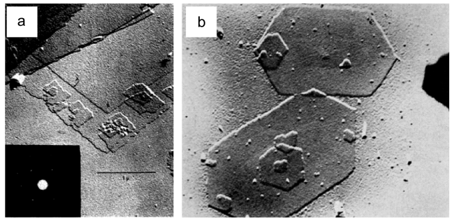
图2 (a) iPB-1的Ⅲ型单层片晶及其对应的电子衍射图[25];(b) 0.5%二甲苯溶液中在100℃下生长的聚乙烯单晶,15 000倍[26]

Fig. 2 (a) Type-Ⅲ single lamella and corresponding electron diffraction pattern of single layer iPB-1[25]. (b) Single crystal of PE grown from 0.5% solution in xylene at 100℃. 15 000 x[26]. Copyright 1970 managed by AIP Publishing, Copyright 1970 John Wiley & Sons, Inc.

In 1984, Booy et al. Prepared amylose single crystals with low degree of polymerization from dilute aqueous solution or water-ethanol mixture. Three different crystal forms were produced depending on the ethanol concentration. Amylose B was obtained from pure water, amylose A from 15% (V/V) ethanol, and amylose V from 40% (V/V) ethanol. The results show that although water and ethanol are listed as low solvents and even precipitants for amylose, small changes in their relative concentrations must cause changes in the conformation of amylose molecules in solution[27]. In 1994, Bu Haishan et al. First obtained single-chain single crystals in solution, and observed the morphology and crystal structure of isotactic polystyrene (PS) single crystals[28]. In 1997, Qian Renyuan et al. Used a transmission electron microscope to observe single-chain single crystals of gutta-percha deposited on a carbon film by spraying particles from a very dilute chloroform solution, and the lower side of the carbon film contacted a filter paper stained with ethanol[29]. Experiments show that the polymer coils in the spray droplets shrink significantly when contacted with non-solvent ethanol, proving that ethanol promotes the crystallization of the sprayed single-chain particles. In 2004, Zhu et al. Studied the effect of the phase morphology of polystyrene-block-polyethylene oxide (PS-b-PEO) diblock copolymer with PEO volume fraction of 37 vol% on the crystallization kinetics in different nano-confined spaces, and obtained various phase morphologies such as double helix dodecahedron (DG), hexagonal cylinder (Hex) and lamellar (Lam)[30]. The phase morphology was characterized by small angle X-ray scattering and transmission electron microscopy techniques, and the crystallization kinetics of the nanoconfined geometry was studied by differential scanning calorimetry (DSC) using Avrami analysis. The results show that the crystallization kinetics of Lam phase is the fastest, and the thermodynamic stability of PEO crystal is higher than that of DG phase and Hex phase. For the crystallization kinetics of the two two-dimensional constrained phases, the crystallization rates of DG phase and Hex phase are similar at low Tc(<35℃), while the crystallization rate of DG phase is slower than that of Hex phase at high Tc(>35℃). It has been shown that PEO crystals are difficult to grow in the DG phase due to the continuous curved channels in the DG phase. In 2013, Su et al. Studied the crystallization behavior of poly (2-vinylpyridine) -block-poly (ε-caprolactone) (P2VP-b-PCL) diblock copolymer in the presence of selective solvent by transmission electron microscopy and atomic force microscopy[31]. As shown in Fig. 3A, B, the addition of water to the P2VP-b-PCL solution of N, N-dimethylformamide can produce elongated truncated rhombic single crystals with uniform size and shape in large quantities. The results show that the adjacent reentrant folding mode plays a major role in solution crystallization, and these findings provide a convenient method for the preparation of homogeneous single crystals in large quantities.
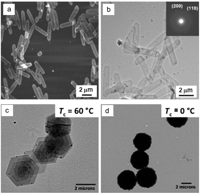
图3 (a) AFM高度图像和(b) TEM明场显微照片:P2VP199-b-PCL310单晶在20℃DMF/水混合物结晶。在(c) Tc = 60℃和(d)Tc = 0℃时分别结晶的iPB-1六角单晶和圆形单晶的TEM图像[31,32]

Fig. 3 (a) AFM height image and (b) TEM bright field micrograph of P2VP199-b-PCL310 single crystals formed inDMF/water mixture at 20℃. The inset shows the corresponding selected area electron diffraction pattern. TEM images of iPB-1 hexagonal and round single crystals crystallized at (c) Tc = 60℃ and (d)Tc = 0℃, respectively[31,32].Copyright 2013, WILEY-VCH Verlag GmbH & Co. KGaA, Weinheim; Copyright 2014, American Chemical Society

In 2014, Miyoshi et al. Used 13C-13C double quantum (DQ) NMR to first determine the chain folding structure in solution-grown crystals of 13C-CH3 labeled iPB-1 mixed with non-labeled iPB1 over a wide range of crystallization temperatures (Tcs)[33]. A comparison of the DQ experimental results and spin dynamics simulations shows that most of the individual chains crystallize at 60 ° C and 0 ° C with a fully adjacent reentrant structure,It is demonstrated that both high Tc and low Tc lead to the formation of unimolecular clusters by the adjacent reentrant structure, while the morphology is highly dependent on the Tc, and it is shown that it is the low polymer concentration rather than the kinetics that leads to the formation of unimolecular clusters in dilute solution. The change in crystal habit from hexagonal at Tc=60℃ to circular at 0 ° C can be rationalized as kinetically driven deposition of monomolecular clusters 32 on the growth front, as shown in Fig. 3C, d. Further, they employed solid-state NMR technique to determine the chain trajectories of type III chiral single crystals of 13C-CH3 labeled iPB-1 blended with unlabeled iPB-1 in dilute solution under low supercooling conditions. The results show that the crystallization process is divided into two steps, (I) cluster formation by self-folding at the pre-crystallization stage and (ii) deposition of nanoclusters as building blocks at the growth front of the single crystal. In 2018, Miyoshi et al. Synthesized PLLA chains labeled with 13C-CH3, and systematically studied the Mw and dynamic effects on the chain folding structure and crystal habit of PLLA labeled with 13C-CH3 by solid-state NMR and atomic force microscopy (AFM)[34]. It is believed that PLLA chains with different Mw initially adopt the same nanocluster by folding (stage I), and that the kinetically controlled nanocluster aggregation process leads to the different morphological characteristics of ΔT (stage ii).

2.2 Melt crystallization

Polymer crystallization requires a driving force. For most polymer materials, the van der Waals forces between molecular chains at room temperature restrict the movement of molecular chains. In the early days, it was believed that only spherulites could grow in melts, until some examples of polymer single crystals growing in melts were found[35,36]. Usually, warming can improve the movement ability of molecular chains. When the temperature is higher than the glass transition temperature of the material and lower than the equilibrium melting point, the thermal energy obtained by the molecular chain in the environment will be higher than the Van der Waals force, resulting in the nucleation and growth of crystals. When the temperature condition is suitable, the polymer single crystal structure can be obtained under the condition of melt. The observation of melt-crystallized polymers confirms its support for the adjacent reentry model[37~41]. Striped micelle crystal nuclei are formed in the melt at the early stage of crystallization, followed by the formation of folded chain crystals[42~44].
In 1963, Symons et al. Studied the crystallization of polytetrafluoroethylene (PTFE) melt by electron microscopy, electron diffraction and optical microscopy. The observed single crystals with the thickness of 150 ~ 900 ~ 900 Å and the molecular chains perpendicular to the basal plane of the crystal indicate that the melt crystallization of PTFE occurs by the chain folding mechanism, which explains the stripe band structure observed on the fracture surface of bulk specimens of dispersed and granular polymers[45]. In 1972, Kovacs and Gonthier obtained polyethylene oxide (PEO) single crystals by ultra-thin film melt crystallization, and studied the effects of crystallization temperature and molecular weight on the morphology of single crystals[46].
In 1993, Toda et al. Studied the three-dimensional shapes of melt-grown polyethylene (PE) single crystals: lenticular (planar) and truncated rhombic (chair-like)[47]. The origin of the chair-like crystal is discussed, and a possible mechanism for the formation of the spiral terrace is proposed, which is based on the distortion caused by the three-dimensional shape of the chair-like crystal. The correlation between lateral spreading, growth kinetics, and three-dimensional shape of the lamellae was investigated by further classification of single crystals with curved cross-sections. In 1997, Liu et al. Prepared poly (ethylene terephthalate) (PET) layered single crystals at different temperatures by closed film melt polymerization[48]. Based on the results of electron diffraction, the "perfect" PET single crystal was confirmed, and the chain arrangement and molecular conformation of the triclinic unit cell were simulated by modeling software. It is found that the molecular chains are inclined to the substrate at different angles at different crystallization temperatures, and the crystal density is affected by the heating history. In 2002, Yan Shouke's team studied the morphology and crystal structure of melt-crystallized ultrathin isotactic poly (1-butene) (iPB-1) films by transmission electron microscopy and electron diffraction[49]. As shown in figs. 4A and 4B, it is observed that the melt-grown iPB-1 single crystal has a hexagonal shape, while the type I crystal transformed from type II shows the morphology of its tetragonal precursor. Electron diffraction shows that the directly formed type I single crystal exhibits an untwinned hexagonal crystal form, rather than the twinned hexagonal crystal form of the converted type I single crystal. Type II crystallization can be bypassed by increasing the crystallization temperature to avoid unstable tetragonal crystallization.
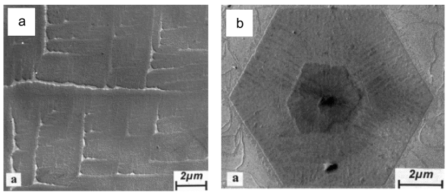
图4 iPB-1薄膜在160℃下热处理15分钟后的基础上,(a) 在95℃下等温结晶30分钟,(b) 在110℃下等温结晶5天原子力显微图像[49]

Fig. 4 (a) BF electron micrograph and of an iPB-1 film that was heat-treated at 160℃ for 15 min and then isothermally crystallized at 95℃ for 30 min. (b) BF electron micrograph of an iPB-1 film that was heat-treated at 160℃ for 15 min and then isothermally crystallized at 110℃ for 5 days[49]. Topographic images of polyethylene single crystals of 32 K fraction grown from the melt.Copyright 2002 Wiley Periodicals, Inc

In 2005, Toda et al. Observed the three-dimensional morphology of PE single crystals grown from dilute solution and melt by atomic force microscopy[50]. The selection rule for the handedness of the spiral terrace was determined by the observation of single crystals, and it was confirmed that the dislocations of the chair screw follow the selection rule for handedness. In 2007, Rastogi et al. Traced the mechanism of crystallization in heterogeneous melt state with the help of solid-state nuclear magnetic resonance. The observation that disentangled segments crystallize faster than entangled segments indicates that homogeneous nucleation occurs faster than heterogeneous nucleation. The effect of the number of entanglements on crystallization is studied, and the conclusion is that the time required for crystallization increases with the increase of the number of entanglements per unit chain[51]. The following year, Gedde et al. Used atomic force microscopy to study the morphology and thermal stability of different sectors in the melt-grown crystals of star-branched polyester PCL containing poly (ε-caprolactone) (PCL) arms. The melt-crystallization process of star-shaped branched and linear PCL films was monitored in real time by thermal atomic force microscopy. Striped wrinkled surfaces were observed in star-shaped branched and linear PCL crystals, and real-time monitoring of melt crystallization proved that this structure was originally present, rather than caused by the collapse of tent-like crystals. In addition, the anisotropy of crystal shape increases with the increase of crystallization temperature[52].
The conditions of melt crystallization and solution crystallization are relatively simple and are mainly affected by the crystallization temperature, so it is easy to obtain a series of crystals. It provides a rich sample for the early analysis of single crystal structure and morphology, and gives birth to a variety of theoretical models of crystallization. Crystallization from melt and dilute solution is still an effective means to study crystallization kinetics at present and in the future.

3 New Crystallization Strategy

3.1 Self-nucleation

The key step in polymer crystallization is nucleation. Solvent-polymer interactions and solubility limits are additional key parameters in polymer solutions. When the concentration is lower than the solubility, the polymer solution is homogeneous and no crystalline structure is formed. When the concentration exceeds the solubility, the interaction between polymers becomes more frequent, and crystals can only be formed by overcoming the nucleation barrier[53~56]. As the temperature approaches the melting point of the polymer, the process of crystallization becomes extremely slow and is often accompanied by heterogeneous nucleation competition with nucleating agents, surfaces, or impurities[56~59]. If the starting time of nucleation and the number density of nuclei are not controlled, the final crystal structure is usually the result of multiple nucleation steps, resulting in complex crystal morphology[56,60,61]. Nucleating agents, surfaces, or impurities help to reduce the energy barrier for nucleation, so it is critical to grow and control the number of nuclei.
In the cultivation strategy of single crystal, by adding the grains of the material itself, it can effectively provide crystallization nucleation points to form large-size single crystals. This strategy is called self-seeding. Different from the narrow melting peak of small molecules, polymer crystals have different melting temperatures due to the different thickness of platelets[62,63]. The number of nuclei in the system can be effectively controlled by adjusting the experimental conditions to ablate most of the randomly generated nuclei. This approach has been extensively studied in thin films and polymer solutions. Almost defect-free and large polymer single crystals can be grown at low supercooling or low supersaturation by the self-nucleation method.
In 1966, Blundell first proposed the concept of self-nucleation in the process of cultivating uniform monolayer polyxylene crystals. He believed that the phenomenon of self-nucleation was very important for crystals, and studied the nature and origin of the crystal nucleus itself through this phenomenon. Compared with melt growth, the nuclei and final crystals produced by self-nucleation are easier to observe, and this work is the first direct study of the nuclei of polymer crystals. In Blundell's experiment, the process of self-nucleation is to prepare a crystal suspension by completely dissolving the polymer solution, and then quench the suspension to crystallize. It was found that the solution retained the memory of the previous suspension over a limited range of dissolution temperatures (Ts). The aim of the first set of experiments is to find out the effect of various experimental parameters on the number of nuclei. The mechanism of nucleus formation is well illustrated by these experiments. Other studies include direct detection of nuclei, detection of light scattering from nuclei in solution, and observation of nuclei in the resulting crystals using electron microscopy. The information of the structure and composition of the crystal nucleus was obtained. Because of the large number of nucleation centers and the small volume of self-nucleated crystals, the final crystal morphology is relatively simple. He found that one of the most important characteristics of self-nucleated crystals is that any crystal obtained by crystallization can show the preparation process of all crystals, and the size of crystals is related to the number of crystal nuclei. Crystals obtained under this crystallization condition retained the memory of the previous suspension, all crystals were equal in size, and the number of crystals was much larger than the number of crystals that lost crystallization memory at the higher dissolution temperature (Ts). The study shows the existence of the inherent crystal nucleus of the polymer itself[64].
The utilization of self-nucleation in melt crystallization can be traced back to the 1970s. Low molecular weight PEO single crystals were obtained by the self-nucleation method in the paper published by Kovacs in 1972. The obtained self-nucleated samples show that the crystal unit initially grows as a layered single crystal with regular crystal planes, similar to the crystal obtained from dilute solution crystallization. By rapidly quenching the sample, the crystal growth was inhibited, resulting in a high-contrast product with all nucleation sites modified, and the homogeneously nucleated melt was transparent. This modification process describes the roughness and surface profile of the crystal edge and lamellar surface. While high contrast can distinguish sheet structures made of folded and fully elongated chains. They found that the shape and thickness of crystal lamellae depend on the molecular weight and crystallization temperature (Tc). Their direct examination of partially representative crystals sheds new light on chain folding and sheet thickening. It should be noted that this study is limited to basic observations on single crystals grown isothermally in an undercooled PEO melt[46].
In 1987, Blundell et al., in the process of studying linear polyethylene, selected materials with low-density crystal nuclei and obtained large-size spherulites[65]. Generally speaking, heating at a temperature much higher than the melting point can completely melt the crystalline region in the melt and avoid it acting as a nucleation site in the subsequent crystallization process. The number of potential nucleation sites can be effectively reduced by heat treatment, so that spherulites grow larger than otherwise. This method was later improved and optimized. In 1991, Cebe was the first to use a "two-stage self-nucleation technique" in the preparation of PPS crystals. In the dissolution stage, PPS powder was dissolved at reflux temperature (254 ° C) into the separated one-third of the total solvent and then immediately transferred to a crystallization vessel, where two-thirds of the total solvent was preheated at the first-stage crystallization temperature (140.0 ° C for both materials). After the formation of the crystal nucleus, it is rapidly cooled to the second stage isotherm. After the single crystals are formed, they are allowed to precipitate in a container for crystallization. The remaining bulk of the solution containing uncrystallized polymer is then removed and fresh solvent is added at the second stage temperature. The above process needs to be repeated to remove most of the non-crystalline polymer components that may affect the study. The experimental results show that the conditions controlled in the self-nucleation method mainly determine the number and properties of the crystal nuclei, and the crystal morphologies obtained at different temperatures are different. The limitation of the experiment is that the nucleated crystals in the solution can not be observed at high temperature, and the properties of the self-nucleated crystals can not be studied after the concentration of the solution is reduced by dilution[66].
In the 1980s, the concept of self-nucleation in the preparation of metal crystals was also mentioned in a large number of literatures, but it was completely different from that in polymers. In 1998, Ivanov introduced in his research a self-nucleation strategy suitable for the growth of large single crystal materials with low thermal conductivity from a melt. This is a method to control the crystal composition by maintaining the "supersaturation" partial pressure of highly volatile components on the melt, and has been applied for the first time to the single crystal preparation of Cd compounds. He also used the gradient freezing method in the preparation method, and finally obtained more perfect CdTe and Cd1-xZnxTe single crystals. The use of nuclei in the melt improves the production of single crystals. The key problem to be overcome is to keep the nuclei in the right position in the container and to ensure that the axial temperature gradient is as small as possible during the growth of the crystal because of the risk of melting of the nuclei at the initial stage of the crystallization process. Another problem is that the melt composition needs to be very strictly controlled during the crystallization process to prevent the crystal from precipitating during the cooling process after growth, so the growth needs to be carried out in a saturated Cd vapor pressure environment, requiring the use of multizone furnaces. The use of this equipment is a novel crystallization idea[67].
Reiter began to grow polymer single crystals by autologous nuclear technology very early, and obtained abundant research results. In his 2009 article, he clearly pointed out that the self-nucleation method involves two steps: first, an already crystallized sample is melted at a temperature slightly above the melting point; Then, the sample was cooled to a lower temperature, at which point the crystal grew from submicroscopic. By growing initial crystals through this two-step growth process, his team "cloned" polymer single crystals whose number density and location could be predetermined to some extent by the thermal history of the starting crystal[68].
In Reiter's 2011 article, it was shown that polymer crystals allow self-nucleation due to kinetically determined platelet thickness and corresponding melting temperature variation, i.e., a small amount of thermodynamically stable residual crystal can be used as a seed from which the melt regrows the crystal. Therefore, when a crystal melts, all the remaining parts are oriented, so the crystal regrows from these seeds. The different crystallization mechanisms of macromolecules and small molecules are explained in detail in this paper[69]. In another article in 2018, he found that the crystallization mode of low molecular weight polyethylene oxide single crystals was self-nucleating. He particularly studied the effect of nucleation temperature (Ts) and heating rate (Vh) on different crystallization modes. Crystallization at 49 ° C resulted in dendritic PEO crystals consisting almost entirely of twice-folded chains. Upon heating these crystals, it was observed that the crystal thickening was caused by a decrease in the average chain folding number[70].
M Müller has also worked to explore self-nucleating crystallization. In 1992, he proposed a new technique for molecular separation during crystallization, the sequential self-nucleation/annealing (SSA) technique. High density polyethylene (HDPE) with bimodal molecular weight distribution was used as the sample and melted at 170 ℃ for 3 min. Then, cool down to 25 ° C at 10 ° C/min to create an initial "standard" thermal history. Subsequently, a heating scan was performed at 10 ° C/min until the selected self-nucleation and annealing temperature (Ts), and the sample was stored isothermally for 5 min and then cooled again at 10 ° C/min to 25 ° C. The sample was then heated again at 10 ° C/min, but this time to a new Ts that was 5 ° C below the previous Ts. This means that crystals not melted at this lower Ts will be annealed at this temperature within 5 min. This was then repeated with the Ts decreasing every 5 ° C relative to the previous step. The two polymers finally obtained in the experiment have similar short chain branching content, and their crystallization and melting behaviors are very similar regardless of the comonomer type. All of them exhibit a wide range of crystallization and melting with a bimodal character. This may be a consequence of the bimodal distribution of polymer short chain branches[71]. In another article in 2015, he summarized the achievements of self-nucleation of crystalline phases in homopolymers, polymer blends, copolymers, and nanocomposites. Self-nucleation is a special nucleation process produced in a given polymer material by inducing chain orientation in the molten or partially molten state, or triggered by self-nucleation. Self-nucleating crystallization methods increase the nucleation density of polymers by several orders of magnitude, resulting in significant changes in their morphology and overall crystallization kinetics. It has been found that self-nucleation can be used as an effective and convenient tool to study the nucleation and crystallization of polymers, which can be performed only by standard scanning differential calorimetry.Self-nucleation is influenced by the structure (homopolymer versus copolymer) and topology (cyclic versus linear, or branched versus linear) of the polymer chain, molecular weight, chemical structure, and molecular orientation. In addition, self-nucleation also provides a way to quantify the nucleation efficiency of additives such as nucleators and nanofillers, establishing a relative scale that allows meaningful comparisons between the nucleation efficiencies of different additives[72].
In the same year, Peters introduced the self-nucleation of polymers with mobility, using bimodal PE as an example. In this study, two kinds of linear high density PE with different molecular weight distribution were specially synthesized, and other homopolymers with fluidity were used for self-nucleation crystallization. The adopted crystallization strategy is based on stretching the macromolecule allowing the formation of nuclei at temperatures above the melting point. He mainly studied the effect of flow conditions on the formation of high temperature crystal nuclei and their nucleation properties, and found that by adding a high molecular weight end to the tail of the molecule,Nuclei can be generated from a relatively low molecular weight PE matrix at high temperature, and the nucleation ability of fibrous nuclei formed by cooling after shearing near the equilibrium melting point was analyzed. These new findings of self-nucleating crystals also show that the crystallization temperature of polymers is a parameter that depends on the whole thermodynamic process, not only on the cooling rate. However, the crystallization temperature and other crystallization parameters of bimodal PE studied by Peters are basically controlled by macroscopic strain after shearing at 142 ℃[73].
In general, the self-nucleation strategy takes full advantage of the melting limit of polymer crystals, which is different from that of small molecular crystals, and is an effective means to cultivate large polymer single crystals. The self-nucleation technique is now mature and has been applied to the study of homopolymers, random and graft copolymers, polymer blends, polymorphic polymers, and nanocomposites. We believe that the self-nucleation method will have a wider range of applications in the future, ranging from semiconductor and microelectronics, micro-purification, surface treatment to medical systems.

3.2 Interface epiphysis

Interfacial attachment is a commonly used method to obtain polymer single crystals. The process of polymer crystallization includes nucleation and growth, in which the nucleation process needs to cross a higher energy barrier[53~56]. By providing a crystalline interface to the amorphous polymer, the surface energy during nucleation can be reduced, thereby promoting rapid crystal growth[74~76]. Unlike self-nucleating one-dimensional point nucleation, interfacial attachment generally provides two-dimensional planes for polymer crystal growth. A variety of different crystal structures can be formed by using the effect of lattice matching by selecting the appropriate crystallization interface[77~80].
Interfacial attachment was first proposed by Baer in 1966. In this paper, the interfacial attachment crystallization of homopolymers on alkali halide single crystals is introduced. He hoped to establish the kinetic mechanism by which polymers grow from small crystals on the surface to intergrown layered crystals, and finally aggregate on the surface to form an oriented network. He achieved interfacial attachment, crystallization on the substrate, by two methods: crystal isothermal soaking (as shown in Figure 5A) and solvent evaporation on the crystal (as shown in Figure 5B). He then floated the polymer on a 0.001 inch polyester film. The film was stretched to 150% of the original length. The unstretched and stretched samples were replicated by first depositing platinum and carbon films, and then placing a 10% aqueous solution of polyacrylic acid (PAA) on the samples. After the PAA was sufficiently hardened, the replica was peeled off from the polylactide film and placed in water, in which the PAA was dissolved. The resulting film was then floated on an electron microscope grid. The results show that the cleaved alkali halide crystals have a unique effect on the crystallization mode of the various polymers studied. Lattice matching is certainly not a criterion for the epitaxial influence of the substrate on the crystalline polymer, as can be seen by the epitaxial growth of PE on all halide surfaces shown in the study. The electron diffraction pattern from the polymer crystal shows that the chains are parallel to the NaCl surface. This phenomenon, in contrast to the usual dissolution crystallization of polymers on amorphous substrates, reveals the influence of directional interaction forces associated with the polymer chain axis on the heterogeneous nucleation process. The solvent undoubtedly affects the interaction of surfaces during crystallization. However, the fact that many polymer-solvent systems exhibit similar crystallization behavior indicates that the influence of the solvent is a secondary factor affecting the crystal orientation[81].
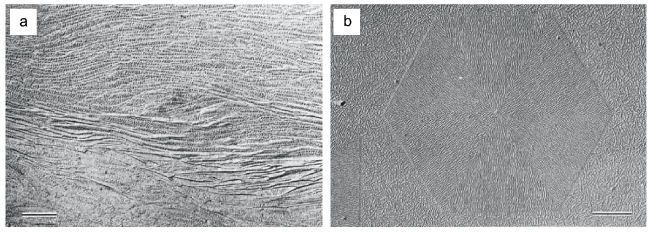
图5 (a)PE在NaCl表面结晶,显微镜下观察到PE的定向网状生长;(b)使用的结晶方法为在NaCl(001)表面结晶,后溶剂在晶体上蒸发,最终在显微镜下观察得到的图像[81]

Fig. 5 (a) Oriented network overgrowth of polyethylene grown on a surface of NaCl. Arrow indicates [110] NaCl direction. Immersion temperature 105℃; C-Pt replica; Shadow angle 45 °; 0.5-μ mark. (b)Incipient polyethylene “rose” structures grown by method B on (001) NaCl surfaces. Arrow indicates [110] direction of NaCl[81].Copyright 1966, John Wiley & Sons, Inc.

In 1972, Baer reported the interfacial epitaxial crystallization method of PE. The relationship between the epitaxial layer of polyethylene film formed on the surface of alkali halide crystal by isothermal solution crystallization and molecular weight, solution concentration and supercooling was studied by electron microscope and other equipment. It was found that in the case of NaCl epitaxy, the growth of the crystal in the monoclinic form is more dominant than the usual orthorhombic form with decreasing deposition thickness. The concentration and the degree of supercooling have a significant effect on the growth rate. He proposed a model of long-distance electrostatic force generated on the surface of alkali halides and used it to explain the phenomenon of "limiting crystal height" at low supercooling[82].
In 1981, Wittmann's team reevaluated the mode of action of nucleating agents selected for the epitaxial crystallization of PE on organic substrates. The interfacial adhesion of polymers on the surface of organic compound crystals has rarely been studied before. He first used conventional optical and electron microscopy techniques to dry PE films several hundred angstroms thick on glass slides with diluted (about 0.5%) p-xylene solution, and then deposited thin crystals of hydrocarbons on these films. The p-triphenyl solution was evaporated dropwise in p-xylene, deposited on clean water, and then extracted directly on a PE-covered slide to give the appropriate p-triphenyl crystals. For anthracene and phthalate, such crystals were obtained directly on PE film by drying a drop of their solution in xylene and water, respectively[83]. Another article in 1983 used benzoic acid as a substrate to study the crystallization of several kinds of polymers, mainly PE. The polymer film was first formed on a microscope slide by evaporating the diluted solution (about 0.5%) in formic acid or xylene, respectively (as shown in Fig. 6). The film was then melted or dissolved in the presence of benzoic acid at a temperature above the melting point of the polymer, and the mixture was recrystallized by slowly moving the slide along the temperature gradient of the hot bar. Benzoic acid was then dissolved in methyl or ethanol, and the polymer film left on the glass was covered with carbon and floated in water. To reveal the layered structure of the polyethylene film, staining and etching methods were employed to produce films thin enough to allow electron diffraction and bright-field imaging[84].
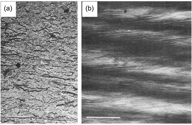
图6 (a)PE薄膜的电子显微照片,用高锰酸试剂蚀刻,分离复制,并用Pt-C遮蔽;(b)类似的聚乙烯薄膜经氯磺酸染色后的电子显微照片[84]

Fig. 6 (a) Electron micrograph of a film of polyethylene etched with permanganic reagent, detachment-replicated and shadowed with Pt-C; scale bar 1 μm. (b) Electron micrograph of a similar PE films stained with chlorosulfonic acid. Lamellae are properly oriented for visualization in only part of the field. A small fraction of the lamellae are oriented at right angles to the main orientation; scale bar 0.5 μm[84]. Copyright © 1983 John Wiley & Sons, Inc.

In 1985, in a collaborative study by Wittmann and Lotz, they introduced a new technique for wrinkled surface modification of polymer crystals. They used the polymer modification method to qualitatively determine the folding orientation of polyethylene under different crystallization conditions. This method is similar to gold modification, but uses the vapor of a crystallizable polymer such as PE as the modification material. Through condensation and crystallization, the highly asymmetric modified molecule is oriented parallel to the folding direction (as shown in Fig. 7). These molecules form a thin layer of tiny crystals with rod-like edges, so they can be observed by conventional transmission electron microscopy. They analyzed the decoration patterns of crystals with different surface structures, compared the decoration patterns of PE prepared under different conditions (from solution, from bulk, from a mixture of low molecular paraffin diluents, etc.), and finally determined that the method is applicable to various polymers under different conditions. Evaporation of polymer vapors and interfacial epitaxial crystallization provide the basis for modification techniques to reveal the orientation characteristics of substrates. This modification technique reveals the functional partition of macromolecular single crystals grown from solution, and it can be used to determine the local folding direction of polymers crystallized under various conditions. This technique shows that under all current crystallization conditions, the outermost layers of the polymer's wrinkled surface are relatively well ordered, and the wrinkles are generally parallel to the macroscopic growth edge[85].
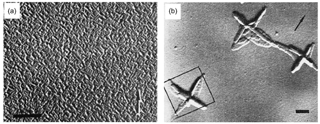
图7 (a) 聚乙烯薄膜(Mw ≈ 20 000)温和冷却至室温结晶后用聚乙烯蒸气修饰后的表面形貌;(b) 聚氧乙烯单晶体(氯苯溶液,c ≈ 0.1%,Tc = 120℃)上修饰聚乙烯蒸气后的表面形貌, 标尺长度:1 μm[85]

Fig. 7 (a)Surface morphology of a thin film of polyethylene (Mw ≈ 20 000) crystallized by moderate cooling to room temperature and decorated with PE vapors. (b) Single crystal of polyoxymethylene (chlorobenzene solution, c ≈ 0.1%, Tc = 120℃) decorated with PE vapors. Scale bar: 1 μm[85].Copyright 1985, John Wiley & Sons, Inc.

In 1990, Lotz reviewed the use of a variety of organic substrates for interfacial epitaxial crystallization. He briefly introduced the preparation, detection and analysis techniques of interfacial epitaxial substrates. Most of the polymers used are common polymers such as iPP and PE. Polymeric materials are more flexible than low molecular weight materials despite their complex chemical structure. The organic substrate crystallizes in the form of highly anisotropic puckered chain sheets, highlighting the interfacial epiphysis-induced orientation. At the end of the paper, he discussed the application status and prospect of interfacial epitaxial crystallization in polymer crystallization from the point of view of science and technology. Organic substrates have three significant improvements over inorganic substrates: (1) better chemical compatibility with polymers, which is adjustable to some extent; (2) The crystal structure is asymmetric, which often leads to a single orientation; (3) has a wide range of characteristic periods, allowing for many interfacial matchings of a given polymer through different crystal phases, contact faces[86].
In 1998, Wittmann and Lotz's group studied the interfacial epitaxial crystallization and AFM structure of isotactic polypropylene (iPP) structure. Accessibility of the rest of the diffraction pattern requires that the sample be subjected to interfacial epitaxial crystallization on an appropriate substrate. As a mild orientation process, interfacial epitaxial crystallization can be used to "fiber" orient the crystal phase. The direction of the chain (or helix) axis is parallel to the substrate surface, so it can be observed with an electron beam norm opposite to the direction of the chain axis (as in fiber science). The specific method is to evaporate a drop of 1% p-xylene or chlorocyclopentane solution by depositing crystals of the matrix on a polymer film (20 ~ 50 nm thick) on a glass cover slide. The polymer and substrate crystals recrystallized after melting are redissolved in their own solvent. The polar nature of the latter ensures that the film is not affected in this process. The surface of the obtained polymer film in contact with the nucleating agent is exposed, which is suitable for AFM work without any further treatment, and is also suitable for electron microscopy of Pt/C shielding and carbon support films[87]. In 2000, Lotz studied the interfacial attachment and polymorphs of poly (lactic acid) (PLA). He cast PLA films (typically in the range of 10 ∼ 50 nm) on glass overlays by evaporating dilute solutions in xylene or dichloromethane. A small amount of hexamethylbenzene (HMB) was deposited on the slide, which was covered by a PLA film. The HMB sublimates and condenses on the colder covering surface, producing sufficiently large single crystals (up to tens of millimeters). It has been shown that two kinds of crystallization of PLA can be produced on a single substrate by interfacial attachment[88].
In 2005, Yan Shouke's team studied the interfacial epitaxial crystallization of poly (butylene adipate) (PBA) on highly oriented PE film. Highly oriented PE films were obtained by melt-stretching technique. The results show that PE has a strong nucleation ability for PBA, and the interfacial attachment of PBA on PE substrate can form PBA crystals under any crystallization conditions (Fig. 8). This is related to the perfect lattice matching between PBA and PE crystals[89]. Further, they investigated the interfacial epitaxial crystallization of isotactic poly (methyl methacrylate) (iPMMA) on highly oriented PE. He used transmission infrared spectroscopy and electron diffraction to study the annealing behavior of amorphous iPMMA films on highly oriented high-density PE substrates. Uniaxially oriented HDPE films were prepared by melt-stretching technique. The accelerated crystallization behavior in the study indicates that there is a special interaction between PE and iPMMA, which is beneficial to the nucleation and crystallization of iPMMA. This special interaction also induces the directional alignment of iPMMA on the PE substrate, with the two polymer chains parallel, that is, the occurrence of heterointerfacial attachment[90].
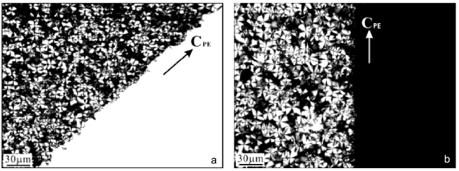
图8 (a)POM显微照片,显示了玻片上的溶液结晶的PBA边界区域,该区域部分被高取向PE衬底覆盖。PE衬底位于图片右下角,箭头表示其分子链方向;(b)从(a)中相同区域拍摄的POM显微照片,但围绕光束逆时针旋转45°[89]

Fig. 8 (a) A POM micrograph shows a boundary region of PBA crystallized from solution on glass slide, which is partially covered with highly oriented PE substrate. The PE substrate is located in the lower right corner of the picture. The arrow indicates its molecular chain direction. (b) A POM micrograph taken from the same area as in (a) but rotated 45° anticlockwise about the light beam[89].Copyright 2006, American Chemical Society

In 2011, Yan Shouke's team studied the interfacial epitaxial crystallization of poly (3-hexylthiophene) (P3HT) on highly oriented PE films. The original P3HT sample was dissolved in chloroform at a concentration of 0.1 wt% and 0.5 wt% at 60 ° C. Due to the thermochromism of P3HT, the solution should be used immediately after preparation. Their team partially removed the sample film of P3HT from the substrate and then evaluated the substrate surface, measuring the distance between all height averages by linear scanning over the sample surface. The results clearly show that P3HT crystallizes on the PE substrate by heterointerface epitaxial crystallization, resulting in the parallel arrangement of P3HT on the PE substrate. Infrared spectroscopy and electron diffraction analysis show that the molecular chains of P3HT are oriented in the film plane and parallel to the chain direction of the PE substrate crystal, while the (100) lattice plane of P3HT is in contact with the PE substrate. The observed interfacial attachment can be explained by the existence of a good one-dimensional lattice match between the (110) lattice plane PE interchain distance and the (100) lattice plane P3HT interchain distance (Fig. 9). This interfacial attachment method provides an effective way to prepare large-area P3HT films with unique orientation structure[78]. This also provides new feasibility for future interface epiphysis.
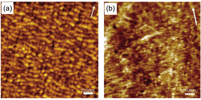
图9 (a)定向聚乙烯(PE)薄膜的原子力显微镜高度图像;(b)生长在PE衬底上的聚(3-己基噻吩)的形态,白色箭头表示PE薄膜制备时的拉伸方向[78]

Fig. 9 AFM height images of (a) an oriented PE film and (b) the morphology of P3HT grown on the PE substrate. The white arrows indicate the drawing directions of PE films during preparation[78].Copyright 2011, American Chemical Society

The method of interfacial adhesion has become more and more mature, and the biggest difference between different researchers using interfacial adhesion method for polymer crystallization lies in the selection of interface and the measurement of lattice matching parameters. The new two-dimensional crystallization mode embodied in the way of crystal formation by interface attachment is also pioneering, which provides a new perspective and thinking for the study of new crystallization modes.

3.3 Controlled volatilization

In the field of polymer physics, due to the planarization of the main chain and the close stacking of the molecular chains in the crystallization process, the properties of single crystal polymer materials are greatly changed compared with those of disordered polymer materials, so that better effects can be achieved in practical applications compared with amorphous polymer materials[56][91~95]. In the study of polymer single crystals, the controlled evaporation of solution is one of the main research methods. In 2019, Reiter et al. Used a controlled volatilization method to accurately synthesize isotactic poly (p-methylstyrene) (iPpMS) through catalytic polymerization and crystallization studies[96]. A series of experiments were carried out by using the device shown in Figure 10 to control the evaporation rate of the solvent in the dilute solution film. Finally, by controlling the evaporation rate of the solvent from the solution, dendritic crystals could be formed, that is, highly ordered polymer crystals could be prepared by controlled evaporation.
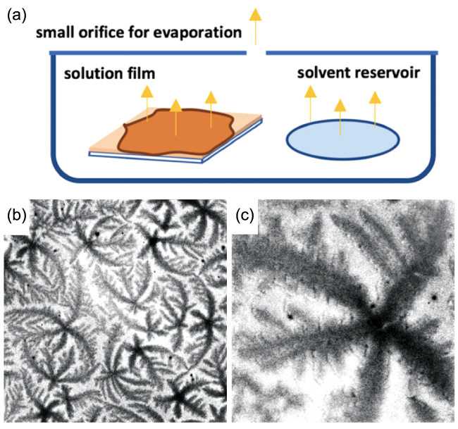
图10 (a)实验装置示意图。该装置设计用于控制蒸发速率。盖上的小孔可使溶剂从稀溶液薄膜中缓慢蒸发。(b),(c)采用甲苯(1.8 μL/min)在室温下缓慢蒸发制备的iPpMS薄膜的光学显微照片(增强)。图像尺寸:(b)400 μm × 400 μm和(c)80 μm × 80 μm[96]

Fig. 10 (a)Schematic of the experimental setup. The setup is designed to control the evaporation rate. The small orifice on the cover allows for slow evaporation of the solvent from the dilute solution film. Optical micrographs (contrast enhanced) of the iPpMS film obtained by slow evaporation of toluene (1.8 μL/min) at room temperature. The size of the images: (b) 400 μm × 400 μm and (c) 80 μm × 80 μm[96].Copyright 2019, American Chemical Society

In terms of time, the use of controlled volatilization in the field of inorganic crystals was published by Somorjai in 1964. In the course of his research, he found that the normal vacuum evaporation rate at a given temperature did not recover immediately after prolonged exposure of the gasified crystal to external Cd or S flux. The new vacuum evaporation rate was low and slowly returned to normal values. These experiments show that the increased surface concentration of Cd or S produced in the experiment leads to diffusion into the bulk of the crystal and a more permanent decrease in the evaporation rate. In order to study the effect of excess of solid Cd or S on the evaporation rate, CdS crystals were intentionally doped with these components, that is, controlled evaporation was used for the study. These crystals were heated in a high temperature environment of Cd or S for a time long enough to establish equilibrium. The homogeneously doped crystals were then quenched and evaporation studies were performed with these samples[97].
Returning to the field of organic crystals, Lin used isotactic poly (3-hexylthiophene) (rr-P3HT) as a solute in 2009, and its toluene solution was confined in a sphere-on-flat geometry to form an axisymmetric capillary microfluid.The continuous "stick-slip" motion of the solution contact line is effectively regulated by solvent evaporation, resulting in a hierarchical "snakeskin" structure with high regularity, in which each microscopic ellipsoid in the "snakeskin" is composed of rr-P3HT nanofiber bundles. This facile one-step deposition technique based on self-assembly by controlled evaporation opens a new way to organize semicrystalline conjugated polymers into two-dimensional ordered patterns in a simple, economical, and controllable manner[98].
In 2018, Li Yuren's research group prepared PLLA-b-PEG block copolymer crystals by controlled temperature quenching in the study of using ultra-thin shell block copolymer crystals to prolong blood circulation time (Fig. 11)[99].
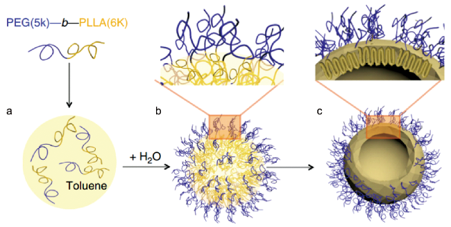
图11 PLLA-b-PEG嵌段共聚物晶体的制备。(a)BCP在甲苯中溶解。(b)95℃下进行乳化。(c)淬火至25℃结晶。该制备过程的驱动力是在甲苯/水界面上的约束导致PLLA结晶,并产生如(c)所示的九重链构造。该约束结晶过程形成了2.5 nm厚的PLLA晶体层,并覆盖着精确控制的均匀PEG刷层[99]

Fig. 11 Fabrication of PLLA-b-PEG block copolymer crystalsomes. (a)Dissolution of the BCP in toluene; (b) emulsification at 95℃; (c) quenching to 25℃ for crystallization. The driving force of this assembly process is confined PLLA crystallization at the toluene/water interface, leading to a ninefold PLLA chain conformation as shown in c. This confined crystallization process also leads to a 2.5 nm thick PLLA crystal layer, covered with a precisely controlled, uniform PEG brush layer[99]

The controlled evaporation of the solvent can realize the slow increase of the solution concentration, which is beneficial to the preparation of regularly arranged polymer single crystals. However, there is still a lack of simple and effective methods for real-time tracking of crystal States in solution, and it is believed that there will be further development in the near future.

3.4 Vapor diffusion

The same monomer can be used to obtain crystalline or non-crystalline polymer materials due to different polymerization methods or different molding conditions. Although there is no difference in chemical structure between crystalline polymer and amorphous polymer, their physical properties are very different[56]. In polymer crystallization, the solution method and the melting method are widely used, but both methods have some disadvantages in different fields. For example, in crystalline nanomaterials, for the solution method, there is usually an unnecessary polymer film outside the nanopore of the template after the solvent evaporates; In the melting method, the crystalline polymer may be thermally degraded or decomposed after high temperature annealing, thus affecting the material properties[100]. Therefore, the vapor diffusion method would be a good choice. However, while thermal annealing or the use of high boiling solvent additives are methods that have been widely explored, the solvent vapor diffusion method has remained somewhat poorly understood for most of the last decade. This does not negate its importance[101]. For the vapor diffusion method, it is shown in McPherson's 2013 article on protein crystallization by an easy-to-understand diagram (Figure 12)[102].
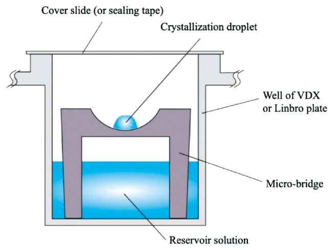
图12 蛋白质结晶应用静滴蒸气扩散法示意图。待结晶溶液置于容器中设置的高台上,不良溶剂通过蒸气扩散的方式,最终使聚合物形成结晶[102]

Fig. 12 Schematic diagram of protein crystallization applying the static drop vapor diffusion method. The solution to be crystallized is placed on a raised platform set in a vessel, and the undesirable solvent is diffused by vapor, eventually causing the polymer to form crystals[102]. Copyright 2014, John Wiley & Sons, Inc

In 1995, Mansky et al., in their study of creating large-area thin films of diblock copolymers, proposed that if the initially prepared film is ordered or disordered and its cylindrical structure is perpendicular to the surface, annealing will result in the same orientation of the film[103]. Within a single grain, annealing excellently preserves the perpendicular cylinder direction while improving the lateral order. Yang et al. Also studied the "solvent annealing" effect of P3HT and methane fullerene polymer solar cells in 2007, and found that the solvent annealing time required for film drying was long.P3HT was also used as the material, and the polymerization time was controlled by spin coating and vapor diffusion. The former polymer loading tended to be disordered in the film, while the latter component ordering could be as high as 67% of the PCBM loading[104].
In 2012, Chen et al. Described the vapor diffusion method in detail. The morphology of PS and PMMA nanostructures depends on whether the expanded polymer is in a partially or fully wetted state, which is characterized by a diffusion coefficient. When the expanded polymer is in a partially wetting state, the polymer wets the nanopore by capillary action, thereby forming polymer nanorods. When the expanded polymer is in a fully wetting state, the polymer forms a wetting layer in the nanopore, thereby forming a polymer nanotube. The solubility parameters of the polymer and solvent are also used to predict the wetting behavior of the expanded polymer in a cylindrical geometry[100]. Based on the article published by Mansky, Sinturel et al. Conducted a more in-depth study in 2013. They identified key challenges to be overcome for the future development of SVA as a practical, reliable, and versatile technique to qualify bulk polymer films across a broad range of technologies, while providing a summary outlook for SVA technology.It includes the brief background of thin film polymer self-assembly, the history of SVA technology and the basic principle of SVA, and clarifies that SVA technology will make it possible for disordered polymers to rearrange and order regularly[101].
In 2018, Zou and Welch continued to study the application of vapor diffusion in organic materials. In order to highlight the advantages of organic dye PDI-DPP-PDI in fullerene-free organic solar cells, they demonstrated how to meet the performance requirements through post-deposition solvent vapor annealing treatment, which further confirmed the application value of vapor diffusion in organic materials[105]. In 2022, Reiter took P3HT as the research object, took a very low concentration solution, and reduced the solubility of P3HT by adding a small amount of poor solvent. The supersaturation of solute can be achieved by reducing the solution temperature, increasing the solute concentration and adding the poor solvent of solute, but the possibility of nucleation of P3HT in the preparation process can not be ruled out in the high concentration solution, and the solvent volatilization will take too much time because of the volatilization of a large amount of solvent, so he chose to add the poor solvent to test. By controlling the volume fraction of the poor solvent, the supersaturation of P3HT can be effectively increased, and the "initiated" nucleation under controllable conditions can be realized, so as to study the critical nucleation size[106].
Vapor diffusion, also known as solvent vapor annealing, can better control the order of the polymer in the process of polymer polymerization, so that the monomer can obtain a certain orientation in the process of polymerization. Vapor diffusion is used to crystallize the polymer, which not only does not produce ineffective polymer crystal film, but also reduces the decomposition of the crystal due to temperature and other reasons. At the same time, compared with disordered polymers, the material properties of ordered polymers can be further improved.

3.5 Surface drag

Liquid drag, also known as meniscus guide coating (MGC), including dip coating, slot die coating, solution shearing blade coating and related techniques, and zone casting, is a very important experimental method in the field of polymer crystallization technology[107~109][110~114][115~119].
In 2013, Han Yanchun's team found that oriented nanofibers in stripes could be obtained by directional diffusion of P3HT flakes on the three-phase contact line of droplets and the formation of one-dimensional crystals. The oriented ribbon structure can be prepared by controlling the tilt angle of the crystal liquid surface by means of liquid surface dragging, and the distance between adjacent stripes can be controlled in the range of 40 to 100 μm[120]. Although the concept of surface drag is not explicitly proposed in this paper, there is no doubt that the experimental method of surface drag is used.
Mannsfeld gave the definition of MGC in his research on morphology control strategies of solution-processed organic semiconductor thin films published in 2014. He pointed out that liquid surface drag is the linear translation of several solution coating technologies using substrates or coating tools to induce aligned crystal growth in the deposited thin films. These methods involve the evolution of the solution meniscus, which acts as an air-liquid interface for solvent evaporation. The solution concentrates as the solvent is removed, and once the supersaturation point is reached, the solute precipitates and deposits as a thin film[107]. The specific methods are divided into zone casting, impregnation volatilization and solution shearing, which are controllable laboratory models for large area film preparation of thin film electronic functional materials. MGC is a promising crystallization technique for regulating the crystallization of organic semiconductors (OSCs) and their film morphology, and because this way OSCs can be processed from solution, it has led to a good prospect for OSCs materials in low-cost, large-area and flexible electronic devices[121,122]. How to control the morphology and crystallinity of OSC thin films is one of the main challenges in achieving high-performance organic electronics applications[117].
The advantages of MGC technology are introduced in Gu's article published in 2018. The deposition method has a key influence on the film morphology, and in particular, the precise control of the morphology of the polymer film, including not only the crystalline domains of the semi-crystalline material (such as crystallinity, grain size, and grain orientation), but also the amorphous domains (such as chain density, chain orientation, and orientation), is important for good charge transport properties. Compared with spin coating, he believes that MGC can solve most of the problems. Due to the inherent directionality of the coating process, the MGC technique can align the deposited OSC layer molecules and is well suited for continuous, steady-state printing, such as R2R processing. At the same time, 90% of the material is discarded when spin coating is used; While using the R2R process in large-scale applications, the material utilization in MGC can be as high as 99%[123]. The MGC technique relies on external shear forces, such as gravity immersed in the coating or mechanical motion in slot die coating, blade coating, and zone casting, to guide and control the molecular alignment in the OSC film. The strength of these forces is determined by the coating speed, so the coating speed has a great influence on the morphology of the deposited salt carbide film[53]. According to the morphology of the salt content film obtained at different coating speeds, it can be divided into three regions, and the salt content of the film generated in the corresponding region can also be reflected by the experiment[117].
In 2020, Pisula proposed the key role of meniscus shape for organic semiconductors, which crystallizes under the guidance of liquid surface drag. In the article, he pointed out the critical role of meniscus shape on fluid flow and crystallization of OSCs during MGC, while demonstrating that angle-dependent dip-coating (ADDC) can precisely control the shape of the meniscus. The use of small meniscus angles during ADDC of 2,7-dioctylbenzothiophene 3,2-bbenzothiophene (C8-BTBT) enhanced crystallization and mass deposition of the salt layer due to an increase in upward flow. The resulting aligned crystalline films with high surface coverage are beneficial for carrier transport in C8-BTBT field effect transistors, thereby providing comprehensive insights into the fundamental mechanisms of OSC[121]. The slot-die coating method was used in the roll-to-roll perovskite solar cell liquid surface drag experiment conducted by Burkitt et al. In 2019[124]. Two years later, Michels published an experimental model of the organic semiconductor 4-toluene-bis-thienyl-diketopyrrole, predicting that surface drag would guide the morphology of solute crystallization after volatilization. It reveals how the interaction between film formation rate and evaporation rate determines the anisotropy and regularity of domain size and shape. If rapid volatilization is adopted, the evaporation drive will rapidly exceed the supersaturation and form an isotropic structure. On the contrary, the loss caused by slow crystallization will form an orientation in the volatilization direction. Although only the case of small molecular solutes is considered in the model, the model can be equally widely applied to polymers and organic-inorganic hybrids, such as perovskites[122].
To sum up, the meniscus guide coating can accurately control the domain size, crystallinity, film morphology and other important characteristics affecting the material properties through the action of solution drag and the control of its speed and other factors, so as to obtain more excellent polymer crystal films in practical applications.

3.6 Topological aggregation

Topological polymerization is a solid phase reaction driven by the alignment of single crystals. The confinement of monomer molecules by the lattice allows us to have precise control over the elasticity, packing, and crystallinity of polymers in topological chemical reactions. Topological polymerization is more attractive than traditional solution polymerization because topological chemical reactions occur under solvent-free and catalyst-free conditions, with high product yields, high selectivity and specificity, and without cumbersome chromatographic purification. In general, ordered packings confer attractive properties to topochemically synthesized polymers. Topological polymerization methods are diverse, including polymerization by [2 + 2], [4 + 4], [4 + 2], and [3 + 2] cycloaddition, as well as polymerization of diynes, triynes, dienes, trienes, and quinodimethane, each of which requires control of appropriate conditions to occur, such as heat, light, or pressure. Each type of reaction requires a unique packing arrangement of the corresponding monomer in order for the reaction to proceed smoothly and form a polymer[125].
In 2021, Li's team used the topological polymerization method to construct polymer single crystals. They used the photochemical [2 + 2] cycloaddition method to synthesize a submillimeter-sized two-dimensional polymer single crystal (T-2DP) through single-crystal to single-crystal transformation, and achieved a successful monomer-to-polymer transformation in the single-crystal state. In the experiment, the team needed to ensure that the conditions were mild, and in this environment, the samples were simply treated with trifluoroacetic acid (TFA) to obtain samples with high exfoliation efficiency. TFA can protonate the triazine core in T-2DP, resulting in solution-like samples with more than 60% polymer content. The exfoliated polymer film can be hundreds of square microns in size, and the film is composed of a single layer of molecules. Finally, the team successfully prepared a long-term, large size and large quantity of diphenyl sulfonic acid film, which opened up a new prospect for the research and application of the basic properties of diphenyl sulfonic acid[126].
In 2022, Dinc Dincă et al. Prepared the first 3D polymer MTBA (methane tetraalkyl tetrakis (benzene-4,1-diyl) tetrakis (anthracene-9-carboxylate)) with permanent porosity by topological polymerization method using C — C bonds. Although MTBA crystals do not have obvious crystal voids, pores appear in polyMTBA due to the large displacement of monomer molecules during polymerization, thus enabling the formation of one-dimensional channels. polyMTBA can be deposited from solution-processed MTBA films onto glass substrates and can be thermally degraded to recover the original monomer. The results show that topological polymerization is an effective method for generating stable, crystalline, and porous 3D organic frameworks[127].
In the same year, Kuntrapakam Hema's team adjusted the regioselectivity of topological polymerization by co-crystallizing with inert aliquots. Regiochemistry of topological chemical reactions relies on crystal filling and biasing, and regioselective chemistry requires precise crystal engineering to achieve. In the topochemical azidane cycloaddition reaction, a 1:1 mixture of 1,4- and 1,5-triazole linked polymers is readily formed. Their team designed a binary isomorphous monomer 1 and a structurally similar dummy molecule 2 to restrict the number of reaction conformations of 1 and obtain polymers. 1 and 2 in an equimolar solution of chloroform-acetone mixture produced two 1:1 Co-crystals Co-I and Co-II. However, Co-Ⅱ undergoes precipitation and polymorphic transformation to Co-Ⅰ during heating. Co-I is isomorphic to 1 and 2 and has a self-sorting array of 1 and 2. Heating Co-I leads to a topochemical azide cycloaddition reaction, thereby producing a 1,4-triazolyl-selective linkage polymer. This technique demonstrates the power of crystal engineering in regioselective chemistry[128].
In 2023, Stoddart's group studied perovskites with rigid cation frameworks (PSCs). Their team found that most of the reported PSCs have poor solubility, which hinders their subsequent functionalization in practical applications and processability in solution. Single crystal to single crystal (SCSC) polymerization (for the preparation of small molecules, one-dimensional and two-dimensional polymer single crystals) provides an effective solution for the preparation of PSCs with extremely high crystallinity and extremely large molecular weight, and this method is environmentally friendly. Therefore, they proposed to use precisely designed monomers for UV-induced topochemical polymerization to produce a large number of [2 + 2] cycloaddition reactions in a light-induced manner. The produced polymer single crystal has high crystallinity and excellent solubility. The follow-up team characterized the samples by X-ray crystallography, electron microscopy, and nuclear magnetic resonance spectroscopy. After anion exchange, PSCs have the function of water purification, and superhydrophobic materials are obtained. This study marks the ability of soluble polymer single crystals to undergo controlled synthesis and comprehensive characterization, which may shed light on the fabrication of characteristic PSCs with different functions[129].
The topological polymerization method has the advantages of high yield, high selectivity and specificity, and more convenient control of conditions, can obtain novel materials with more stability, excellent performance and functionalization, and lays a research foundation for specialized functional materials.

4 Application of polymer single crystal functionalization

4.1 Monocrystalline substrate modification

The typical structures of polymer crystals include spherulite, dendrite, extended chain platelet, fibrous crystal and shish-kebab[130~133][134~136][137~140][141~143][144~147]. Among them, polymer single crystals are plate-like crystals with regular geometric shapes, usually formed by folding molecular chains back and forth[148]. The chain is perpendicular to the lamellar surface or inclined to the two-dimensional plane. At present, there are few studies on single crystal substrates, mainly including single crystal as a template to load nanoparticles and single crystal fluorescence modification[149].
The advantage of polymer single crystal is that when the end-functionalized polymer forms a monolithic folded sheet single crystal, the chain end is excluded from the crystal surface and can couple with various nanoparticles (NPs) to form a nano-sandwich structure. Free Janus nanoparticles (with a non-centrosymmetric structure with a single core surrounded by a compartmentalized crown-like structure) can be obtained after the coupling reaction and the dissolution of polymer single crystals, providing a unique method for the synthesis of asymmetric nanoparticles[150]. When a polymer single crystal is used as a substrate, the method is called "polymer single crystal templating" (PSCryT) method[150~166]. PSCryT uses surface chemical coupling Similar to self-assembled monolayers (SAM), the advantage of using polymer single crystals (PSC) for nanoparticle assembly is that SAM is usually confined to a solid (e.g., silicon wafer) substrate, while PSC is free-standing in solution[167~170]. Li Yuren's group proposed the PSCryT method and has been working on the unique function of the polymer single crystal template.
In 2006, Li's group first reported the use of polymer layered single crystals as a solid substrate to create a graphic functional (thiol) surface and immobilize gold nanoparticles (AuNPs)[151]. At that time, the solution crystallization of PEO had been widely studied, and large and uniform single crystals could be easily obtained. The self-nucleation method was used to obtain large square layered PEO single crystals. Because of the planar geometry of the single crystals, AuNPs were also asymmetrically functionalized. The bottom of AuNPs was functionalized by PEO, and the top was covered by functional groups (tetraoctylammonium bromide TOAB or hexanedithiol). Two years later, they prepared thiol-terminated poly (ethylene oxide) (HS-PEO) single crystals by self-nucleation method, which also realized the asymmetric functionalization of AuNPs. As shown in Fig. 13, HS-PEO was used as a substrate to immobilize AuNPs, and this method was called "solid-state grafting"[152]. In the same year, Janus AuNPs functionalized with two different types of polymer chains on the other side of AuNPs by combining "solid-state grafting" and "grafting" methods with HS-PEO as the substrate were also reported[150]. The use of polymeric single crystals as substrates is advantageous because they have higher throughput than self-assembled monolayers. Dissolution of single crystals also leads to NPs with well-defined polymer patches (functional groups). This method can be used as a general method for the synthesis of polymer-functionalized Janus NPs, and is expected to achieve controllable assembly and tunable optical and electronic properties of NPs.
图13 (a)HS-PEO(2 K)单晶和(b,c)5 nm AuNP覆盖的HS-PEO(2 K)单晶的TEM显微照片。插图显示了FFT模式。(d)用5 nm AuNPs孵育后的HO-PEO(2 K)单晶。(e,f)金NP覆盖的HS-PEO(48.5K)单晶[152]

Fig. 13 TEM micrographs of (a) HS-PEO(2K) single crystals and (b, c) 5 nm AuNP-covered HS-PEO(2K) single crystals. The inset shows the FFT pattern. (d) HO-PEO(2K) single crystals after incubation with 5 nm AuNPs. (e, f) AuNP-covered HS-PEO(48.5K) single crystals[152]. Copyright 2008, American Chemical Society

In 2009, Li's team developed a new method for large-scale production of NP sheets with programmable patterns using PSCryT method[153]. By assembling NPs in situ during the polymer crystallization process (self-nucleation method for HS-PEO single crystals), as shown in Fig. 14, more complex NP patterns can be obtained on these single crystals, enabling precise control of three features of the pattern at different length scales, namely the distance between NPs, the width and length of the framework/chain, and the distance between the framework/chain.
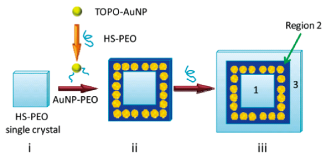
图14 (i)HS-PEO片状单晶,在加入金胶体之前已经形成。PEO链与片状法线平行,硫醇基团在晶体表面。当金胶体被添加到HS-PEO溶液中时,AuNP-PEO共轭物通过位置交换反应形成。AuNP-PEO共轭物在已经形成的单晶周围结晶,产生AuNP框架(ii)。在这些共轭物用完后,PEO继续在AuNP框架周围结晶,形成空白边缘(iii)。1、2和3表示图案的三个不同区域[153]

Fig. 14 (i) A HS-PEO lamellar single crystal, which has already formed prior to the addition of gold colloid. The PEO chains are parallel to the lamellar normal and the thiol groups are on the crystal surface. As gold colloid is added to the HS-PEO solution, AuNP-PEO conjugates are formed via the place exchange reaction. The AuNP-PEO conjugates crystallize around the already formed single crystals, generating AuNP frames (ii). After these conjugates are exhausted, PEO continue to crystallize around the AuNP frames, forming a blank margin (iii). 1, 2, and 3 in part iii denote the three distinct regions of the pattern[153]. Copyright 2009, American Chemical Society

In 2010, Li's research group demonstrated that polymer single crystals can be used as a general substrate for immobilization of NPs[155]. By using polyethylene oxide, polycaprolactone (single crystal growth by self-nucleation method) and polyethylene block polyethylene oxide as a single crystal substrate,Gold, magnetic and semiconductor nanoparticles were immobilized on the surface of polymer single crystal substrate by pretreatment or solution mixing, and then different types of Janus nanoparticles and nanoparticle clusters of different polymers were formed by single crystal dissolution. In the same year, facing the challenge of synthesizing Janus nanoparticles (JNPs) with diameters less than 20 nm, Wang et al. Used atom transfer radical polymerization to grow polymer brushes on gold nanoparticles (AuNPs) with diameters of 6 and 15 nm immobilized on polymer single crystals[154]. JNPs with two-compartment polymer brushes, such as PEO/poly (methyl methacrylate), PEO/poly (tert-butyl acrylate), and PEO/polyacrylic acid, were experimentally synthesized. The amphiphilic nature of the particles can be controlled by adjusting the grafting density and molecular weight of the polymer brush.
In 2011, Li Yuren's research group provided a new method for synthesizing functional Janus nanoparticles by using polymer single crystal template method[164]. High molecular single crystals of bifunctional polymers composed of thiol and carboxylic acid or tert-butyl hydroxy carbon (BOC) protected amino groups, these high molecular single crystals act as templates on which nanoparticles NPs (Au or Fe3O4) are attached via covalent bonds with the exposed thiol groups on the surface of the single crystals, while introducing asymmetric modification and end-group functionalization to the NP surface. After immobilization, the "free" surface of NPs was covered with a layer of dodecyl thiol (DDT). Finally, the nanoparticles are separated from the surface of polymer single crystals to form functionalized Janus NPs, which can be used to fabricate ordered nanoparticle ensembles.
In 2012, the research group introduced a convenient method for the synthesis of amphiphilic Janus silica nanoparticles (SiNPs) with two-chamber polymer brushes by combining "polymer single crystal template" and "grafting" techniques[157]. Alkoxysilane-terminated poly (ε-caprolactone) (PCL-SiOR) single crystals were prepared by self-nucleation method, and silica gel nanoparticles were immobilized on the surface of the single crystals. Subsequently, atom transfer radical polymerization (SI-ATRP) of N-isopropylacrylamide was performed on the exposed surface of SiNPs. The dissolution of polymer single crystals resulted in Janus nanoparticles with amphiphilic two-compartment poly (ε-caprolactone) (PCL) and poly (N-isopropylacrylamide) (PNIPAM) polymer brushes. The Janus particles of this method show a lower thermal transition temperature and a much narrower transition range than SiNPs with uniformly grafted PNIPAM brushes. This unique behavior is attributed to the presence of PCL patches on the surface of Janus particles: hydrophobic interactions between these patches on different particles provide a greater driving force for the aggregation of Janus particles in the LCST temperature range[157].
In order to develop a low-cost and high-yield template for the synthesis of heterogeneous nanoparticles, Zhang et al. Reported a new polymer single crystal substrate method for directional self-assembly of heterogeneous nanoparticles[156]. A self-nucleation method was used to form PSCs composed of hydroxyl-terminated polycaprolactone (PCL-OH) with hydroxyl groups on the surface, and polymer single crystals were used to guide the self-assembly of nanoparticles, resulting in bicomponent Fe3O4-Pt, Fe3O4-Au, SiO2-Pt, and SiO2-Au and tricomponent Fe3O4-Pt-Au heterogeneous nanoparticles. This approach is generally applicable to different nanoparticle systems, as long as there are special interactions between the first adsorbed nanoparticle and the PSC and between the first and second adsorbed nanoparticles[156].
In the following two years, Li Yuren's research group used the polymer single crystal substrate method to self-assemble nanomotors[158,159]. In 2013, the research group used the self-nucleation method to grow the PSC of R-hydroxy-ω-thiol-terminated polycaprolactone (HO-PCL-SH), and R-hydroxy-ω-thiol-terminated PCL was selected because these two types of functional groups were selected to conjugate the PSC with the target nanoparticles, and AuNP, Fe3O4NP, and PtNP were directly self-assembled onto the surface of the quasi-two-dimensional PSC to form a nanomotor[158]. This approach opens up tremendous opportunities for future miniaturization and mass production of nanoengines and other applications including sensors and directional delivery. In 2014, the research group crystallized a biodegradable polymer containing terminal functional sulfhydryl groups, namely polycaprolactone (PCL-SH), in solution to form a hexagonal polymer single crystal with surface sulfhydryl groups, and then used the pre-adsorbed AuNPs as seeds to deposit silver nanoparticles (AgNPs) by silver enhancement method. The AuNP-decorated polycaprolactone single crystal (Au-PCL), once placed in an aqueous solution of H2O2, can decompose H2O2 to form oxygen bubbles, which in turn provides a direct driving force for pushing Ag-PCL[159].
In 2014, Li's team provided a simple method for the synthesis of "dumbbell" nanoparticle dimers by one-step coupling of nanoparticles and quasi-two-dimensional polymer single crystals[160]. Bifunctional poly (ε-caprolactone) (PCL) was crystallized in solution to give polymer single crystals (PSCs) with extended chains, which were used as templates to immobilize various nanoparticle NPs, including AuNPs, Fe3O4NPs, and SiNPs. A dense layer of NPs was formed on both sides of the sheet surface, and the PCL PSCs were dissolved in the solvent to obtain NP dimers without further treatment.
In the following year, the research group reported a shape-controllable independent sheet composed of nanoparticles by PSCryT method. Nanoparticle assemblies were obtained by self-assembly technique using nanoparticles and polymer single crystals as basic building blocks[161]. The two-dimensional assembly includes four different components, namely PCL single crystals or polyethylene glycol (PEG) single crystals, 1,6-hexanedithiol (HDT), and two different types of nanoparticles, namely magnetic iron oxide nanoparticles (Fe3O4NP) with metallic platinum nanoparticles (PtNP) or semiconducting cadmium selenide nanoparticles (CdSeNP). The function of the two-dimensional single crystal is to serve as a template for nanoparticle assembly; Nanoparticles, together with HDT, synergistically cross-link single crystals into a robust class of two-dimensional hybrid materials.
In 2016, Zhou et al. Of Li's research group combined the advantages of the traditional "grafting-to" and "grafting-from" methods to synthesize polymer brushes, and used a fundamentally different method from previous reports, the "self-assembly assisted grafting-to" method, to achieve the synthesis of polymer brushes with controllable structure and high grafting density on the plane[165]. Alkoxysilane-terminated poly (ε-caprolactone) (PCL) was used as a model system to grow PSC templates, functionalizing the chain ends, whose thickness was regulated by the crystallization temperature (Tc). The end-functionalized PCL is preassembled into a two-dimensional single wafer, the terminal functional groups of the polymer chains are guided to assemble into a two-dimensional pattern with a controlled areal density, and the chemical coupling of the single wafer with the solid substrate forms a polymer brush. For a given molecular weight, the chain-fold structure can be precisely controlled by changing the crystallization temperature, which can ultimately be used to adjust the grafting density of subsequent polymer brushes[171].
In 2017, Mei et al. Of Li's research group used PSCs as a template to provide a directional assembly method to precisely assemble NPs into well-defined independent frameworks[162]. PEO single crystal (grown by solution crystallization of dimethoxy, self-nucleation method) was used as a template to direct the crystallization of block copolymer (BCP) poly (ethylene oxide) -b-poly (4-vinylpyridine), which directs AuNPs to form AuNP framework. The reported method may become a new approach to the synthesis of precisely assembled, free-standing cyclic NP chains and nanorings.
The following year, Li's research group proposed a bottom-up method "polymer single crystal assisted grafting (PSCAGT)" to synthesize gradient polymer brushes with pre-designed and precisely controlled grafting density gradients and patterns, as shown in Figure 15[163]. Because PEO brushes have been widely used in antifouling and biomedical applications, PEO with the same molecular weight and polydispersity index but different chain ends (triethoxysilane and hydroxyl) were experimentally selected to prepare polymer brushes. The experimental results show that the PEO114-OH dilutes the surface density of — SiOR group in PSC. During the growth of PSC, the composition of the two polymers in PSC gradually changes due to the changing polymer ratio in the solution by adding PEO114-OH. The gradient starts from the center of the crystal, and the brush is similar to a nanoscale pyramid. The slope of the gradient can also be controlled. By changing the addition rate of PEO114-OH, pyramids with different degrees of chain grafting density variation were obtained, resulting in different slopes, and polymer brushes with trapezoidal and smooth gradient structures with pyramidal micropatterns were successfully synthesized[163].
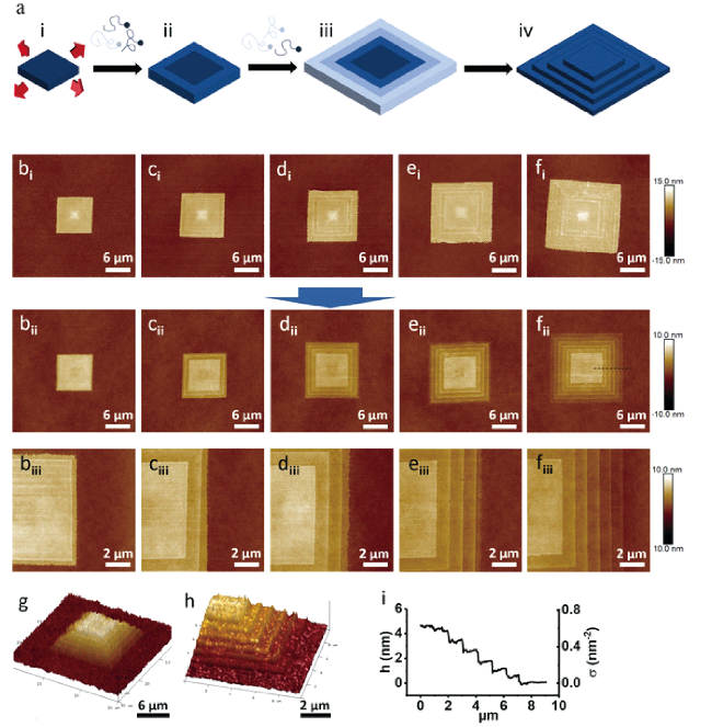
图15 梯田梯度PEO聚合物刷:(a)合成程序,(bi~fi)具有1~5个同心带的PEO单晶,(bii~fii)PEO 刷子有 1~5 个同心带,(biii~fiii)是bi~fi的放大图像,(g,h)具有5个条带的梯田梯度PEO刷的3D图像,(i)高度剖面和相应的σ,从虚线区域测量fiii[163]

Fig. 15 Terraced gradient PEO polymer brush. (a) Synthesis procedure. (bi~fi) PEO single crystal with 1~5 concentric bands; (bii~fii) PEO brushes with 1~5 concentric bands. (biii~fiii) are enlarged images of (bii~fii). (g,h) 3D images of the terraced gradient PEO brush with five bands. (i) height profile and the corresponding σ, measured from dash line area in fiii[163]. Copyright 2018 Wiley-VCH Verlag GmbH & Co. KGaA, Weinheim

In 2020, Li Yuren's group reported a new diblock copolymer brush synthesized by PSCAGT method, which can achieve efficient coupling. The resulting diblock copolymer brushes show relatively high grafting density and also retain the original monocrystalline morphology with high fidelity, providing a unique approach for patterning polymer brushes[172]. Triblock copolymer poly (ethylene oxide) -b-poly (L-lactic acid) -b-poly (3- (triethoxysilyl) propyl methacrylate) (PEO-b-PLLA-b-PTESPMA) was designed as a model polymer, PLLA was used as a crystal block to grow single crystals (PLLA block has the function of single crystal template and brush block), and PTESPMA was used as a coupling block to grow single crystals. Triblock single crystals were obtained by solution crystallization. The PLLA blocks were crystallized into rhombic sheets, and the PEO and PTESPMA blocks were crystallized on the surface of the crystals. The chemical coupling of PTESPMA to the glass surface results in the formation of PEO-b-PLLA brushes, with the PTESPMA block forming a cross-linked layer underneath the brush. This method can also prepare polymer brushes on low-dimensional curved or patterned surfaces.
Recently, some researchers have successfully prepared single crystal structures with aggregation-induced fluorescence effect by introducing special fluorescent groups into the molecular chain. The target molecule 1,4-bis (2-cyano-2-phenylethenyl) benzene (b-CNDSB) becomes an aggregation-induced emission (AIE) active substance by introducing a cyano group. In dilute solution, b-CNDSB displays a twisted conformation and very weak fluorescence. By carefully controlling the growth conditions, in green single crystals, the molecules exhibit nearly planar conformation and J-aggregation, resulting in high luminescence efficiency. The formation of 2D single crystals is believed to be driven by strong π-π interactions and multiple hydrogen bonds. Intense emission can be observed from the edge of the crystal when excited using a 365 nm UV lamp. Intense green electroluminescence from the side of the single crystal was observed from all the devices, and the results show that the single crystal structure can not only achieve high luminescence, but also be used in light-emitting transistors and achieve very high mobility[149].
Polymer single crystal substrate method was initially used to immobilize nanoparticles for patterning and asymmetric functionalization. Subsequently, it was proved that polymer brushes could be grown on the surface of the substrate, Janus NPs could be modified, and small size Janus NPs could be synthesized. After that, it becomes a low-cost and high-yield heterogeneous nanoparticle synthesis template to directionally assemble nanoparticles and realize their various functions.

4.2 Photoelectric response polymer single crystal

In 2000, Heeger, MacDiarmid and Shirakawa were awarded the Nobel Prize in Chemistry for the discovery and development of conducting polymers[173~175][176~178][179~181]. It is common sense that plastics do not conduct electricity, so they can be used as insulating materials for wire cladding, socket switches, etc. However, the discovery of conductive polymers in the mid-1970s changed the long-standing concept that polymers can only be insulators, and then developed polymer materials with optical and electrical activities.
In the past few decades, conjugated polymers have been widely studied due to their excellent optoelectronic properties[182~186]. Compared with inorganic semiconductors, conjugated polymers have the advantages of light weight, strong corrosion resistance, good environmental stability and low production cost[187~191]. Conductive polymers have become alternative materials for optoelectronic devices. For example, conductive polymers have been successfully used in solar cells, light-emitting diodes, chemical sensors, thin film transistors, field effect transistors and other fields[192~198][199,200][201][202~205][206~208]. Compared with amorphous polymers, crystalline polymers have flat main chains and close packing of adjacent chains, and their photoelectric properties can be greatly improved[209]. While the single-crystalline polymer can play a better photoelectric performance because of its perfect ordering of molecular chains, no grain boundaries, good interface contact and small charge defects[55,209 ~219].
To optimize the electrical performance, Kim et al. Developed a P3HT structure with strong π-π interactions aligned with the current direction in PED. During solution crystallization, P3HT chains self-nucleate via π-π interactions. The solvent vapor pressure in the closed reaction tank suppresses the rapid evaporation of the solvent and induces efficient self-nucleation to produce high-quality, long single-crystal nanowires by controlling the π-π stacking of P3HT units during crystallization[212].
Ma et al. Developed a new crystallization method, solvent-assisted crystallization, to grow high-quality regioregular poly (3-butylthiophene) (rr-P3BT) single crystals. They kept 0.2 wt% rr-P3BT THF solution at 70 ° C for 5 H and then slowly cooled to room temperature. The rr-P3BT film was drop-cast on a glass substrate or a mica surface coated with an amorphous carbon film, and the solvent was slowly evaporated. The rr-P3BT film was finally immersed in a mixture of nitrobenzene and THF for several days until the solvent was evaporated. As shown in fig. 16, needle-like rr-P3BT layered single crystals up to millimeters in length were successfully grown using the solvent-free crystallization method. In a single crystal, the molecules are aligned perpendicular to the sheet in an extended chain conformation[213].
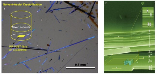
图16 (a)偏光光学显微镜下溶剂辅助结晶的rr-P3BT单晶显微照片;(b)扫描电子显微镜下溶剂辅助结晶的典型P3BT单晶的显微照片,从右上角的放大插图中可以识别出在15.6 nm和104 nm之间变化的薄层厚度[213]

Fig. 16 Micrograph of a typical P3BT single crystal from solvent-assist crystallization under scanning electron microscopy. Lamellar thickness varying between 15.6 nm and 104 nm can be identified from enlarged inset picture in up-right corner. Schematic diagrams of molecular packing in the lamellar crystals, molecular chain direction c and growth direction b are also included as the inset[213]. Copyright 2006, Elsevier Ltd.

Jeon et al. Found a simple and effective method to control the morphology and size of conducting polymer nanostructures for their orderly growth. Organic single crystals of monopotassium 4-sulfobenzoate (KSBA) were used as soluble templates.Below 7 ° C, KSBA was precipitated in aqueous medium as single microsized crystals with a shape similar to hexagonal plates.When pyrrole monomers were added to the KSBA solution together with ferric chloride as an oxidant, the pyrrole was polymerized in a hexagonal plate-like morphology mimicking the shape of the single crystal of KSBA. Conductive polypyrrole (PPy) hexagonal microplates (length 50 ~ 100 μm, width 10 ~ 20 μm, thickness 0.8 ~ 1.2 μm) were synthesized on their surfaces. For the first time, the hexagonal plate morphology of the conductive polymer was obtained, and the conductivity was as high as 400 S/cm. Experiments show that the surface-induced polymerization of organic crystals of conducting polymers can replicate the shape of organic single crystals when the organic single crystals are present in the polymerization medium. This approach can be widely used to fabricate sensors, templates, catalyst supports, and alternatives to carbon materials[211].
Xiao proposed a simple method to prepare needle-like single crystals of poly (3-octylthiophene) (P3OT) by tetrahydrofuran vapor annealing. The original P3OT sample was dissolved in chloroform at a concentration of 0.06% (w/V). The substrate was placed inside a cylindrical container with radius and height of 1.0 cm, 2.0 cm and 3.0 cm, respectively. The solution was dropped onto the substrate, and then the container was covered with a lid. After the solvent was completely evaporated, the crystal film was obtained. A small open container filled with THF was placed in an airtight container below the film at an ambient pressure of 35 ° C for solvent vapor annealing. The resulting single crystal backbone is parallel to the long axis of the crystal and the side chains are perpendicular to the substrate. The P3OT single crystal based field effect transistor shows a charge carrier mobility of 1.54×10⁻⁴cm2/(Vs) and an on/off current ratio of 37. This work demonstrates that crystallization conditions can modulate molecular orientation, contributing to further studies of structure-property relationships in conducting polymers[217].
Xiao prepared P3HT and P3OT by tetrahydrofuran vapor annealing and controlled solvent evaporation, respectively (Fig. 17). When the films were annealed for 42 H, the P3HT single crystals were mainly needle-like crystals with lengths of 20 – 60 μm and diameters of 1 – 2.2 μm. In the field effect transistor, the current is parallel to the length axis of the single crystal, and the mobility of the P3HT single crystal is 1.57×10⁻³cm2/(Vs),P3OT and the mobility of the single crystal is 0.62 cm2/(Vs). When P3HT and P3OT single crystals have the same molecular conformation with the π-π stacking direction parallel to the length axis of the crystal and the main chain parallel to the substrate, the mobility of P3HT single crystal is about 20 times that of P3OT. Compared with P3OT, P3HT has a shorter alkyl side chain length, resulting in a higher mobility. This indicates that the alkyl side chain acts as a barrier to carrier migration between poly (3-alkylthiophene) (P3AT) -like polymers[218].
图17 (a)未退火的P3HT晶体形态,(b)退火12 h的P3HT晶体形态,(c)退火20 h的P3HT晶体形态,(d)退火42h的P3HT晶体形态[218]

Fig. 17 Time-dependent morphology of the P3HT crystals with different annealing times of 0 (a), 12 (b), 20 (c), and 42 h (d)[218]. Copyright 2010, American Chemical Society

Rahimi et al. Used tetrahydrofuran as a solvent to prepare P3HT solutions with concentrations of 0.1 to 10 mg/mL, which were heated to 82 ° C to completely dissolve the polymer. These solutions were then filtered using a 0.45 μm PTFE filter, the temperature of the solution being controlled with an accuracy of 0.1 ° C using a silicone oil bath thermostat. In order to obtain the film from the solution containing the single crystal, they preheated the substrate to Tc, spin-cast 200 μL of the solution onto a UV ozone-cleaned silicon wafer or a 400-mesh copper grid, and then dried in a vacuum oven at room temperature for 1 H to finally obtain a large single crystal of P3HT[219].
Single crystalline poly (3,4-ethylenedioxythiophene) (PEDOT) nanoneedles exhibiting fast conductance switching were first synthesized by Su using an interfacial polymerization process. The tip nanoneedle has an average length of 50 nm and width of 15 nm. EDOT dissolved in dichloromethane was used as the lower organic layer and ferric chloride dissolved in deionized water as the upper layer. Ferric chloride promoted the oxidative coupling polymerization of EDOT at the aqueous/organic interface. After 2 days, the aqueous layer was carefully collected for purification. The electronic conduction behavior of the single crystal was investigated and a field-induced conductance switching of the response time in milliseconds was found[216]. Nuraje also synthesized polyaniline (PANI) and PPy single crystal nanoneedles for the first time by interfacial polymerization. Aniline or pyrrole monomer was dissolved in dichloromethane (5 mL, 1 mg/mL) to form the bottom organic layer, and the oxidant ferric chloride was dissolved in deionized water (5 mL, 0.1 mg/mL) to form the upper aqueous layer. After the interface system was established, the water layer was collected after 48 H. Oxidative coupling occurs between the PANI or PPy monomer of the organic layer and ferric chloride of the aqueous layer to nucleate at the interface. These multimeric nanocrystals grow into the water layer and then disperse into the water layer in the form of nanoneedles. To increase the crystallinity, a lower concentration of monomer and oxidant solution was employed to extend the crystallization time. The dimensions are 63 nm × 12 nm for PANI and 70 nm × 20 nm for PPy. The conductance switching time of the obtained crystalline polymer between the insulating state and the conducting state reaches the order of milliseconds[214].
Cho et al. Developed single-crystal PEDOT nanowires with ultra-high conductivity using liquid bridge-mediated nanotransfer printing and vapor phase polymerization. 3,4-Ethylenedioxythiophene (EDOT) monomer was first used to self-nucleate crystallization within the nanoscale channels of the mold, catalyzed by ferric chloride. PEDOT nanowires are grown according to the pattern arrangement in the mold, then transferred directly to a specific location on the substrate, and finally the nanowire array is generated by printing process. The PEDOT nanowires have a close-packed single crystal structure with orthorhombic lattice units. The conductivity of single crystal PEDOT nanowires is 7619 S/cm on average and up to 8797 S/cm[210].
Zenoozi used P3HT homopolymer and block copolymer to prepare single crystals and nanofibers in a series of solvents such as toluene, xylene and anisole. It was found that the crystallization temperature, the molecular weight of the P3HT block and the presence of the terminal coil block are important factors affecting the size of the single crystal nucleus. In P3HT: phenyl-C71-butyric acid methyl ester (PC71BM) photovoltaic cell, the pre-designed film was used as the active layer, and the device characteristics were studied. It was found that when single crystals and nanofibers were developed from good solvents, the crystal structure would be more ordered, resulting in higher current density[209].
Wu et al. Studied the formation of P3HT crystals in supersaturated solution, proposed a self-nucleation method in situ in solution, and obtained highly ordered large single crystals. The concentration gradient of the poor solvent is formed by vapor diffusion in the solution system, and the precise control of the supersaturation in time and space is realized. Finally, the nucleation density is greatly reduced while maintaining a limited growth rate, resulting in the formation of long needle-like crystals. The spectral results (as shown in fig. 18) show that the obtained single crystal can absorb long-wave light and has broad application prospects in the field of energy[55].
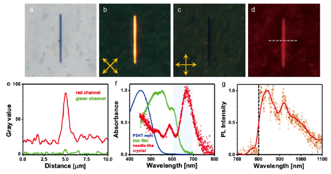
图18 P3HT晶体的光学显微照片(放置时间=10 min,生长时间=4 h)。图像尺寸为25 μm×25 μm。(a)明场。(b)在交叉偏振器下,晶体的长轴与偏振器和分析仪成45°角。(c)在交叉偏振器下,晶体的长轴与偏振器成0°角。(d)显示红色发射颜色的光致发光图像。(e,d)中虚线所示横截面的R和G通道的强度分布。(f)P3HT熔体在280℃下的归一化吸收光谱(蓝色)、室温下的滴铸薄膜(绿色)和类似于(a~d)中所示的针状晶体(红色)。(g)长通滤波器后收集的针状晶体的光致发光光谱(在600~700 nm激发,在(f)中标记成阴影区域)[55]

Fig. 18 Optical micrographs of a P3HT crystal (theating = 10 min, tgrowth = 4 h). Image sizes are 25 μm × 25 μm. (a) Bright field. (b) Under crossed polarizers, the long axis of the crystal is at an angle of 45° to both the polarizer and the analyzer. (c) Under crossed polarizers, the long axis of the crystal is at an angle of 0° to the polarizer. (d) Photoluminescence image showing a red emission color (HBO lamp, excitation at 450~500 nm, emission >500 nm, recorded by a CCD color camera). (e) Intensity profiles of the R and G channels for the cross section indicated by the dashed line in (d). (f) Normalized absorption spectra of P3HT melt at 280℃ (blue), drop-casted thin film at room temperature (green), and a needle-like crystal (red) similar to the one shown in (a~d). (g) Photoluminescence spectrum of a needle-like crystal (excitation at 600~700 nm, marked as the shaded area in (f)) collected after a long pass filter (marked as a dashed line in (g))[55].Copyright 2020, American Chemical Society

5 Conclusion and prospect

In this paper, we review the history and progress in the study of polymer single crystals, and discuss in detail the crystallization strategies and functional applications of polymer single crystals. The cultivation of polymer single crystals requires precise control of the crystallization driving force to ensure a smaller number of nuclei and a slower growth rate. By using different single crystal growth strategies, the regular arrangement of disordered polymer chains can be achieved, thus improving its performance. More importantly, the formation process of polymer single crystal reveals the general law of the microscopic motion of soft matter, which greatly enriches the research connotation of polymer physics and deepens human understanding of the motion of matter at the molecular level. We believe that polymer single crystal has rich theoretical significance and broad application prospects, and will flourish in the historical stage of "the second century of polymer science", and integrate into all aspects of human production and life with a new look.
[1]
Staudinger H. A Source Book in Chemistry, 1900-1950, Henry M(Ed.). England: Harvard University Press, 1968. 259-264.

[2]
Frey H, Johann T. Polym. Chem., 2020, 11(1): 8.

[3]
Till P H Jr. J. Polym. Sci., 1957, 24(106): 301.

[4]
Keller A. Philos. Mag., 1957, 2(21): 1171.

[5]
Fischer E W. Z. Für Naturforschung A, 1957, 12(9): 753.

[6]
Flory P J. Principles of Polymer Chemistry. Ithaca: Cornell University Press, 1953.

[7]
Stack G M, Mandelkern L, Voigt-Martin I G. Polym. Bull., 1982, 8(9-10): 421.

[8]
Tanabe Y, Strobl G R, Fischer E W. Polymer, 1986, 27(8): 1147.

[9]
Roe R, Gieniewski C, Vadimsky R G. J. Polym. Sci. B, 1973, 11: 1653.

[10]
(a) Xu J J, Ma Y, Hu W B, Rehahn M, Reiter G. Nat. Mater., 2009, 8(4): 348;

(b) Ren J, Ma A, Li J, Jiang X, Ma Y, Toda A, Hu W. Eur. Phys. J. E, 2010, 33: 189.

[11]
Flory P J. J. Chem. Phys., 2004, 17 (3):223.

[12]
Zhang S J, Han J R, Gao Y, Guo B H, Reiter G, Xu J. Macromolecules, 2019, 52(19): 7439.

[13]
Zhang S J, Guo B H, Reiter G, Xu J. Macromolecules, 2020, 53(9): 3482.

[14]
Wang Z Q, Duan R L, Pang X A, Wu R L, Guo B H, Xu J. Macromolecules, 2023, 56(3): 999.

[15]
Wunderlich B, Melillo L, Cormier C M, Davidson T, Snyder G. J. Macromol. Sci. B, 1967, 1(3): 485.

[16]
Bennett R. In Perrys Chemical Engineers Handbook, 6th ed. New York: McGraw-Hill, 1984. 25-40.

[17]
Myerson A. Handbook of Industrial Crystallization, Butterworth-Heinemann, 2002.

[18]
Rånby B G, Noe R W. J. Polym. Sci., 1961, 51(155): 337.

[19]
Storks K H. J. Am. Chem. Soc., 1938, 60(8): 1753.

[20]
Jaccodine R. Nature, 1955, 176(4476): 305.

[21]
Lauritzen Jr J I, Hoffman JD. Journal of Research of the National Bureau of Standards: Physics and chemistry. Section A, 1959, 63.

[22]
Hu W B, FrenkelD. Macromolecules, 2004, 37(12): 4336.

[23]
Zhou Y J, Hu W B. J. Phys. Chem. B, 2013, 117(10): 3047.

[24]
Keller A. Rep. Prog. Phys., 1968, 31(2): 623.

[25]
Holland V F, Miller R L. J. Appl. Phys., 1964, 35(11): 3241.

[26]
Patel G N, Patel RD. J. Polym. Sci. A-2 Polym. Phys., 1970, 8(1): 47.

[27]
Buleon A, Duprat F, Booy F, Chanzy H. Carbohydr. Polym., 1984, 4(3): 161.

[28]
Bu H H, Chen E Q, Xu S Y, Guo K X, Wunderlich B. Journal of Polymer Science Part B: Polymer Physics, 1994, 32 (8):1351.

[29]
Liu L Z, Su F Y, Zhu H S, Li H, Zhou E L, Yan R F, Qian R Y. J. Macromol. Sci. B, 1997, 36(2): 195.

[30]
Sun L, Zhu L, Ge Q, Quirk R P, Xue C C, Cheng S ZD, Hsiao B S, Avila-Orta C A, Sics I, Cantino M E. Polymer, 2004, 45(9): 2931.

[31]
Su M, Huang H Y, Ma X J, Wang Q A, Su Z H. Macromol. Rapid Commun., 2013, 34(13): 1067.

[32]
Hong Y L, Miyoshi T. ACS Macro Lett., 2014, 3(6): 556.

[33]
Hong Y L, Yuan S C, Li Z, Ke Y T, Nozaki K, Miyoshi T. Phys. Rev. Lett., 2015, 115(16): 168301.

[34]
Wang S J, Yuan S C, Chen W, Zhou Y, Hong Y L, Miyoshi T. Macromolecules, 2018, 51(21): 8729.

[35]
Lotz B, Lovinger A J, Cais R E. Macromolecules, 1988, 21(8): 2375.

[36]
Mehta R, Keawwattana W, Guenthner A L, Kyu T. Phys. Rev. E, 2004, 69(6): 061802.

[37]
Calvert P. J. Macromol. Sci., 1980, 14(2): 201.

[38]
Bank M I, Krimm S. J. Polym. Sci. A-2 Polym. Phys., 1969, 7(10): 1785.

[39]
Geil P H. Polymer single crystals. Krieger Publishing Company, 1963. 5.

[40]
Hoffman J. Soc. Plastics Engrs. Trans., 1964, 4 (1).

[41]
Wunderlich B. Macromolecular Physics. New York: Academic Press, 1973.

[42]
Wang Z G, Hsiao B S, Sirota E B, Agarwal P, Srinivas S. Macromolecules, 2000, 33(3): 978.

[43]
Manabe N, Yokota Y, Minami H, Uegomori Y, Komoto T. J. Electron Microsc., 2002, 51(1): 11.

[44]
D’Ilario L, Martinelli A, Piozzi A. J. Macromol. Sci. B, 2002, 41(1): 47.

[45]
Symons N K J. J. Polym. Sci. A Gen. Pap., 1963, 1(9): 2843.

[46]
Kovacs A J, Gonthier A. Kolloid-Z.u.Z.Polymere, 1972, 250(5): 530.

[47]
Toda A, Keller A. Colloid Polym. Sci., 1993, 271(4): 328.

[48]
Liu J, Geil P H. J. Macromol. Sci. B, 1997, 36(1): 61.

[49]
Zhang B, YangD C, Yan S K. J. Polym. Sci. B, 2002, 40(23): 2641.

[50]
Toda A, Okamura M, Hikosaka M, Nakagawa Y. Polymer, 2005, 46(20): 8708.

[51]
LippitsD R, Rastogi S, Höhne G W H, Mezari B, Magusin P C M M. Macromolecules, 2007, 40(4): 1004.

[52]
Núñez E, Vancso G J, Gedde U W. J. Macromol. Sci. B, 2008, 47(3): 589.

[53]
Welch P, Muthukumar M. Phys. Rev. Lett., 2001, 87 (21):218302.

[54]
Lorenzo A T, Müller A J. J. Polym. Sci. B, 2008, 46(14): 1478.

[55]
Wu T Y, Pfohl T, Chandran S, Sommer M, Reiter G. Macromolecules, 2020, 53 (19): 8303.

[56]
Rubinstein M, Colby R H. Polymer Physics. New York: Oxford University Press, 2003. Vol.23.

[57]
Thanh N T K, MacLean N, Mahiddine S. Chem. Rev., 2014, 114 (15):7610.

[58]
Menczel J, Varga J. J. Therm. Anal., 1983, 28(1): 161.

[59]
Xu J, Reiter G, Alamo R. Crystals, 2021, 11(3): 304.

[60]
Zhang B, Chen J B, Baier M C, Mecking S, Reiter R, Mülhaupt R, Reiter G. Macromol. Rapid Commun., 2015, 36(2): 180.

[61]
Agbolaghi S, Abbaspoor S, Abbasi F. Prog. Polym. Sci., 2018, 81: 22.

[62]
Wang G, Harrison I R. Thermochim. Acta, 1994, 231: 203.

[63]
Rastogi S, LippitsD R, Peters G W M, Graf R, Yao Y F, Spiess H W. Nat. Mater., 2005, 4(8): 635.

[64]
BlundellD J, Keller A. J. Macromol. Sci. B, 1968, 2(2): 301.

[65]
Waddon A J, Hill M J, Keller A, BlundellD J. J. Mater. Sci., 1987, 22(5): 1773.

[66]
Chung J S, Cebe P. Polymer, 1992, 33(8): 1594.

[67]
Ivanov Y M. J. Cryst. Growth, 1998, 194(3-4): 309.

[68]
Xu J J, Ma Y, Hu W B, Rehahn M, Reiter G. Nat. Mater., 2009, 8(4): 348.

[69]
Reiter G. Chem. Soc. Rev., 2014, 43(7): 2055.

[70]
Wang B H, Tang S H, Wang Y, Shen C Y, Reiter R, Reiter G, Chen J B, Zhang B. Macromolecules, 2018, 51(5): 1626.

[71]
Müller A J, Hernández Z H, Arnal M L, Sánchez J J. Polym. Bull., 1997, 39(4): 465.

[72]
Michell R M, Mugica A, Zubitur M, Müller A J. Polymer Crystallization I. Cham: Springer International Publishing, 2015. 215.

[73]
Balzano L, Rastogi S, Peters G. Macromolecules, 2011, 44(8): 2926.

[74]
Alfonso G C, Russell T P. Macromolecules, 1986, 19(4): 1143.

[75]
Mayes A M. Macromolecules, 1994, 27(11): 3114.

[76]
Cadek M, Coleman J N, Barron V, Hedicke K, Blau W J. Appl. Phys. Lett., 2002, 81(27): 5123.

[77]
Butté R, Carlin J F, Feltin E, Gonschorek M, Nicolay S, Christmann G, SimeonovD, Castiglia A, Dorsaz J, Buehlmann H J, Christopoulos S, Baldassarri Höger von Hög G, Grundy A JD, Mosca M, Pinquier C, Py M A, Demangeot F, Frandon J, Lagoudakis P G, Baumberg J J, Grandjean N. J. Phys.D: Appl. Phys., 2007, 40(20): 6328.

[78]
Zhou H X, Jiang SD, Yan S K. J. Phys. Chem. B, 2011, 115(46): 13449.

[79]
Li Y P, Guo Z X, Xue M L, Yan S K. Macromolecules, 2019, 52(11): 4232.

[80]
Wang Y, Yan L T, Dastafkan K, Zhao C A, Zhao X B, Xue Y Y, Huo J M, Li S N, Zhai Q G. Adv. Mater., 2022, 34(7): 2006351.

[81]
Koutsky J A, Walton A G, Baer E. J. Polym. Sci. A-2 Polym. Phys., 1966, 4(4): 611.

[82]
Wellinghoff S, Rybnikar F, Baer E. J. Macromol. Sci. B, 2006, 10(1): 1.

[83]
Wittmann J C, Lotz B. J. Polym. Sci. Polym. Phys. Ed., 1981, 19(12): 1837.

[84]
Wittmann J C, Hodge A M, Lotz B. J. Polym. Sci. Polym. Phys. Ed., 1983, 21(12): 2495.

[85]
Wittmann J C, Lotz B. J. Polym. Sci. Polym. Phys. Ed., 1985, 23(1): 205.

[86]
Wittmann J C, Lotz B. Prog. Polym. Sci., 1990, 15(6): 909.

[87]
Stocker W, Schumacher M, Graff S, Thierry A, Wittmann J C, Lotz B. Macromolecules, 1998, 31(3): 807.

[88]
Cartier L, Okihara T, Ikada Y, Tsuji H, Puiggali J, Lotz B. Polymer, 2000, 41(25): 8909.

[89]
Sun Y J, Li H H, Huang Y, Chen E Q, Zhao L F, Gan Z H, Yan S K. Macromolecules, 2005, 38(7): 2739.

[90]
Liu J, Wang J J, Li H H, ShenD Y, Zhang J M, Ozaki Y, Yan S K. J. Phys. Chem. B, 2006, 110(2): 738.

[91]
BowerD I, Solis F J. Am. J. Phys., 2003, 71(3): 285.

[92]
Stamm M. Macromol. Chem. Phys., 2006, 207(8): 787.

[93]
Mandelkern L. Crystallization of Polymers. 2nd ed. Cambridge, UK: Cambridge University Press, 2004.

[94]
Tadokoro H. Structure of Crystalline Polymers. Krieger Publishing Company, 1990..

[95]
Fried J. Polymer Science & Technology. Pearson Education, 2014.

[96]
Wu T Y, Valencia L, Pfohl T, Heck B, Reiter G, Lutz P J, Mülhaupt R. Macromolecules, 2019, 52(13): 4839.

[97]
Somorjai G A, JepsenD W. J. Chem. Phys., 1964, 41(5): 1394.

[98]
Byun M, Laskowski R L, He M, Qiu F, Jeffries-EL M, Lin Z Q. Soft Matter, 2009, 5(8): 1583.

[99]
Qi H, Zhou H, Tang Q Y, Lee J Y, Fan Z Y, Kim S, Staub M C, Zhou T A, Mei S, Han L, PochanD J, Cheng H, Hu W B, Li C Y. Nat. Commun., 2018, 9: 3005.

[100]
Chen J T, Lee C W, Chi M H, Yao I C. Macromol. Rapid Commun., 2013, 34(4): 285.

[101]
Sinturel C, Vayer M, Morris M, Hillmyer M A. Macromolecules, 2013, 46(14): 5399.

[102]
McPherson A, Gavira J A. Acta Crystallogr. Sect. F Struct. Biol. Commun., 2014, 70(1): 2.

[103]
Mansky P, Haikin P, Thomas E L. J. Mater. Sci., 1995, 30(8): 1987.

[104]
Li G, Yao Y, Yang H, Shrotriya V, Yang G, Yang Y. Adv. Funct. Mater., 2007, 17(10): 1636.

[105]
McAfee S M, Payne A J, Hendsbee AD, Xu S T, Zou Y P, Welch G C. Sol. RRL, 2018, 2(9): 1800143.

[106]
Wu T Y, Chandran S, Zhang Y, Zheng T Z, Pfohl T, Xu J, Reiter G. Macromolecules, 2022, 55(8): 3325.

[107]
Diao Y, Shaw L, Bao Z N, Mannsfeld S C B. Energy Environ. Sci., 2014, 7(7): 2145.

[108]
Gu XD, Shaw L, Gu K, Toney M F, Bao Z N. Nat. Commun., 2018, 9: 534.

[109]
Patel B B, Diao Y. Nanotechnology, 2018, 29(4): 044004.

[110]
Sele C W, Charlotte Kjellander B K, Niesen B, Thornton M J, van der Putten J B P H, Myny K, Wondergem H J, Moser A, Resel R, van Breemen A J J M, van Aerle N, Heremans P, Anthony J E, Gelinck G H. Adv. Mater., 2009, 21(48): 4926.

[111]
Rogowski R Z, Darhuber A A. Langmuir, 2010, 26(13): 11485.

[112]
Zhang K, Marszalek T, Wucher P, Wang Z Y, Veith L, Lu H, Räder H J, Beaujuge P M, Blom P W M, Pisula W. Adv. Funct. Mater., 2018, 28(50): 1805594.

[113]
Gans A, Dressaire E, Colnet B, Saingier G, Bazant M Z, Sauret A. Soft Matter, 2019, 15(2): 252.

[114]
GrossoD. J. Mater. Chem., 2011, 21(43): 17033.

[115]
Giri G, Verploegen E, Mannsfeld S C B, Atahan-Evrenk S, KimD H, Lee S Y, Becerril H A, Aspuru-Guzik A, Toney M F, Bao Z N. Nature, 2011, 480(7378): 504.

[116]
Haase K, Zessin J, Zoumboulis K, Müller M, Hambsch M, Mannsfeld S C B. Adv. Electron. Mater., 2019, 5(6):1900067.

[117]
Lu Z J, Wang C Q, Deng W, Achille M T, Jie J S, Zhang X J. J. Mater. Chem. C, 2020, 8(27): 9133.

[118]
Galindo S, Tamayo A, Leonardi F, Mas-Torrent M. Adv. Funct. Mater., 2017, 27(25): 1700526.

[119]
Tamayo A, Riera-Galindo S, Jones A O F, Resel R, Mas-Torrent M. Adv. Mater. Interfaces, 2019, 6(22): 1900950.

[120]
Gao X A, Han Y C. Chin. J. Polym. Sci., 2013, 31(4): 610.

[121]
Zhang K, Wang Z Y, Marszalek T, Borkowski M, Fytas G, Blom P W M, Pisula W. Mater. Horiz., 2020, 7(6): 1631.

[122]
Michels J J, Zhang K, Wucher P, Beaujuge P M, Pisula W, Marszalek T. Nat. Mater., 2021, 20(1): 68.

[123]
Gu XD, Shaw L, Gu K, Toney M F, Bao Z N. Nat. Commun., 2018, 9: 534.

[124]
BurkittD, Greenwood P, Hooper K, RichardsD, Stoichkov V, BeynonD, Jewell E, Watson T. MRS Adv., 2019, 4(24): 1399.

[125]
Hema K, Ravi A, Raju C, Pathan J R, Rai R, Sureshan K M. Chem. Soc. Rev., 2021, 50(6): 4062.

[126]
Hu F, Hao W B, MückeD, Pan Q Y, Li Z B, Qi H Y, Zhao Y J. J. Am. Chem. Soc., 2021, 143(15): 5636.

[127]
Sun C Y, Oppenheim J J, Skorupskii G, Yang L M, Dincă M. Chem, 2022, 8(12): 3215.

[128]
Hema K, Raju C, Bhandary S, Sureshan K M. Angew. Chem. Int. Ed., 2022, 61(40): e202210733.

[129]
Liu Y, Guan X R, WangD C, Stoddart J F, Guo Q H. J. Am. Chem. Soc., 2023, 145(24): 13223.

[130]
Price F P. J. Polym. Sci., 1959, 37(131): 71.

[131]
Olley R H, BassettD C. Polymer, 1989, 30(3): 399.

[132]
Li L, Chan C M, Yeung K L, Li J X, Ng K M, Lei Y G. Macromolecules, 2001, 34(2): 316.

[133]
Tanaka H, Nishi T. Phys. Rev. A, 1989, 39(2): 783.

[134]
Kurz W, FisherD J. Acta Metall., 1981, 29(1): 11.

[135]
Seiler M. Chem. Eng. Technol., 2002, 25(3): 237.

[136]
Rosso M, Brissot C, Teyssot A, Dollé M, Sannier L, Tarascon J M, Bouchet R, Lascaud S. Electrochim. Acta, 2006, 51(25): 5334.

[137]
Wunderlich B, Mielillo L. Die Makromolekulare Chemie: Macromolecular Chemistry and Physics, 1968, 118 (1): 250.

[138]
Hikosaka M. Polymer, 1987, 28(8): 1257.

[139]
Hikosaka M. Polymer, 1990, 31(3): 458.

[140]
Yan L, Häußler M, Bauer J, Mecking S, Winey K I. Macromolecules, 2019, 52(13): 4949.

[141]
Hill M J, Keller A. J. Macromol. Sci. B, 1969, 3(1): 153.

[142]
Peterlin A. Int. J. Fract., 1975, 11(5): 761.

[143]
Zhang J, Li J, Han Y. Macromol. Rapid Commun., 2004, 25 (11): 1105.

[144]
Hobbs J K, Miles M J. Macromolecules, 2001, 34(3): 353.

[145]
Kimata S, Sakurai T, Nozue Y, Kasahara T, Yamaguchi N, Karino T, Shibayama M, Kornfield J A. Science, 2007, 316(5827): 1014.

[146]
Somani R H, Yang L, Zhu L, Hsiao B S. Polymer, 2005, 46(20): 8587.

[147]
Hsiao B S, Yang L, Somani R H, Avila-Orta C A, Zhu L. Phys. Rev. Lett., 2005, 94(11): 117802.

[148]
Goodwyn M. Ghost Worlds: A Guide to Poltergeists, Portals, Ecto-Mist, & Spirit Behavior. Llewellyn Worldwide, 2011.

[149]
Deng J A, Xu Y X, Liu L Q, Feng C F, Tang J A, Gao Y, Wang Y, Yang B, Lu P, Yang W S, Ma Y G. Chem. Commun., 2016, 52(11): 2370.

[150]
Wang B B, Li B, Zhao B, Li C Y. J. Am. Chem. Soc., 2008, 130(35): 11594.

[151]
Li B, Li C Y. Journal of the ACS, 2006, 129 (1):12.

[152]
Li B, Ni C Y, Li C Y. Macromolecules, 2008, 41(1): 149.

[153]
Li B, Wang B B, Ferrier R C M Jr, Li C Y. Macromolecules, 2009, 42(24): 9394.

[154]
Wang B B, Dong B, Li B, Zhao B, Li C Y. Polymer, 2010, 51(21): 4814.

[155]
Xu L A, Li H, Jiang X, Wang J X, Li L, Song Y L, Jiang L. Macromol. Rapid Commun., 2010, 31(16): 169.

[156]
Zhang H, Dong B, Zhou T A, Li C Y. Nanoscale, 2012, 4(24): 7641.

[157]
Zhou T A, Wang B B, Dong B, Li C Y. Macromolecules, 2012, 45(21): 8780.

[158]
Dong B, Zhou T A, Zhang H, Li C Y. ACS Nano, 2013, 7(6): 5192.

[159]
Liu M, Liu L M, Gao W L, Su MD, Ge Y, Shi L L, Zhang H, Dong B, Li C Y. Nanoscale, 2014, 6(15): 8601.

[160]
Zhou T A, Dong B, Qi H, Lau H K, Li C Y. Nanoscale, 2014, 6(9): 4551.

[161]
Zhang H, Liu M, Zhou T A, Dong B, Li C Y. Nanoscale, 2015, 7(25): 11033.

[162]
Mei S, Qi H, Zhou T A, Li C Y. Angew. Chem. Int. Ed., 2017, 56(44): 13645.

[163]
Mei S, Li C Y. Angew. Chem. Int. Ed., 2018, 57(48): 15758.

[164]
Dong B, Li B, Li C Y. J. Mater. Chem., 2011, 21(35): 13155.

[165]
Zhou T A, Qi H, Han L, BarbashD, Li C Y. Nat. Commun., 2016, 7: 11119.

[166]
Mei S, Wilk J T, Chancellor A J, Zhao B, Li C Y. Macromol. Rapid Commun., 2020, 41(15): 2000228.

[167]
AllaraD L. Biosens. Bioelectron., 1995, 10(9-10): 771.

[168]
Ji H F, Dabestani R, Brown G M, Britt P F. Chem. Commun., 2000,(6): 457.

[169]
Schreiber F. Prog. Surf. Sci., 2000, 65(5-8): 151.

[170]
Schoenbaum C A, SchwartzD K, Medlin J W. Acc. Chem. Res., 2014, 47(4): 1438.

[171]
Zhou T A, Qi H, Han L, BarbashD, Li C Y. Nat. Commun., 2016, 7: 11119.

[172]
Mei S, Wilk J T, Chancellor A J, Zhao B, Li C Y. Macromol. Rapid Commun., 2020, 41(15): e2000228.

[173]
McGehee M D, Heeger A J. Adv.Mater., 2000, 12 (22): 1655.

[174]
Heeger A. Chem.Soc.Rev., 2010, 39 (7):2354.

[175]
Heeger A J, Kivelson S, Schrieffer J R, Su W P. Rev. Mod. Phys., 1988, 60(3): 781.

[176]
MacDiarmid A G, Chiang J C, Richter A F, Epstein A J. Synth. Met., 1987, 18(1-3): 285.

[177]
MacDiarmid A G, Chiang J C, Halpern M, Huang W S, Mu S L, Nanaxakkara LD, Wu S W, Yaniger S I. Mol. Cryst. Liq. Cryst., 1985, 121(1/4): 173.

[178]
MacDiarmid A G. Rev.Mod.Phys. 2001, 40 (14): 2581.

[179]
Shirakawa H, Louis E, MacDiarmid A, Chiang C K, Heeger A J. Chem.Commun., 1977, (16): 578.

[180]
Shirakawa H, McDiarmid A, Heeger A. Chem.Commun., 2003, 2003 (1): 1.

[181]
Shirakawa H, Ito T, Ikeda S. Makromol. Chem., 1978, 179 (6):1565.

[182]
Dai C H, Liu B. Energy Environ. Sci., 2020, 13(1): 24.

[183]
Feng L H, Zhu C L, Yuan H X, Liu L B, Lv F T, Wang S. Chem. Soc. Rev., 2013, 42(16): 6620.

[184]
Guo X, Baumgarten M, Müllen K. Prog. Polym. Sci., 2013, 38(12): 1832.

[185]
Inal S, Rivnay J, Suiu A O, Malliaras G G, McCulloch I. Acc. Chem. Res., 2018, 51(6): 1368.

[186]
Melling D, Martinez J G, Jager E W H. Adv. Mater., 2019, 31(22): 1808210.

[187]
Qiu Z J, Hammer B A G, Müllen K. Prog. Polym. Sci., 2020, 100: 101179.

[188]
Tuncel D, Demir H V. Nanoscale, 2010, 2(4): 484.

[189]
Vahdatiyekta P, Zniber M, Bobacka J, Huynh T P. Anal. Chim. Acta, 2022, 1221: 340114.

[190]
Wang S H, Zuo G Z, Kim J, Sirringhaus H. Prog. Polym. Sci., 2022, 129: 101548.

[191]
Xu Y, Cui Y, Yao H F, Zhang T, Zhang J Q, Ma L J, Wang J W, Wei Z X, Hou J H. Adv. Mater., 2021, 33(22): e2101090.

[192]
Bruner C, Novoa F, Dupont S, Dauskardt R. ACS Appl. Mater. Interfaces, 2014, 6(23): 21474.

[193]
Kim J S, Lee J H, Park J H, Shim C, Sim M, Cho K. Adv. Funct. Mater., 2011, 21(3): 480.

[194]
Kim M, Jo S B, Park J H, Cho K. Nano Energy, 2015, 18: 97.

[195]
Liu F, ChenD A, Wang C, Luo K Y, Gu W Y, Briseno A L, Hsu J W P, Russell T P. ACS Appl. Mater. Interfaces, 2014, 6(22): 19876.

[196]
Lu L Y, Zheng T Y, Wu Q H, Schneider A M, ZhaoD L, Yu L P. Chem. Rev., 2015, 115(23): 12666.

[197]
Aernouts T, Vanlaeke P, Geens W, Poortmans J, Heremans P, Borghs S, Mertens R, Andriessen R, Leenders L. Thin Solid Films, 2004, 451-452: 22.

[198]
Kim J H, Park J H, Lee J H, Kim J S, Sim M, Shim C, Cho K. J. Mater. Chem., 2010, 20(35): 7398.

[199]
Han T H, Lee Y, Choi M R, Woo S H, Bae S H, Hong B H, Ahn J H, Lee T W. Nat. Photonics, 2012, 6(2): 105.

[200]
Admassie S, Zhang F L, Manoj A G, Svensson M, Andersson M R, Inganäs O. Sol. Energy Mater. Sol. Cells, 2006, 90(2): 133.

[201]
Yoon H, Chang M, Jang J. Adv. Funct. Mater., 2007, 17(3): 431.

[202]
Park YD, Lee H S, Choi Y J, KwakD, Cho J H, Lee S, Cho K. Adv. Funct. Mater., 2009, 19(8): 1200.

[203]
Qiu L Z, Lee W H, Wang X H, Kim J S, Lim J A, KwakD, Lee S, Cho K. Adv. Mater., 2009, 21(13): 1349.

[204]
Wang C C, Rivnay J, Himmelberger S, Vakhshouri K, Toney M F, Gomez ED, Salleo A. ACS Appl. Mater. Interfaces, 2013, 5(7): 2342.

[205]
Yang H, Shin T J, Yang L, Cho K, Ryu C Y, Bao Z. Adv. Funct. Mater., 2005, 15(4): 671.

[206]
Lee J Y, Lin C J, Lo C T, Tsai J C, Chen W C. Macromolecules, 2013, 46(8): 3005.

[207]
Lim J A, Kim J H, Qiu L Z, Lee W H, Lee H S, KwakD, Cho K. Adv. Funct. Mater., 2010, 20(19): 3292.

[208]
Liu H Q, Reccius C H, Craighead H G. Appl. Phys. Lett., 2005, 87(25): 253106.

[209]
Zenoozi S, Agbolaghi S, Poormahdi E, Hashemzadeh-Gargari M, Mahmoudi M. Macromol. Res., 2017, 25(8): 826.

[210]
Cho B, Park K S, Baek J, Oh H S, Koo Lee Y E, Sung M M. Nano Lett., 2014, 14(6): 3321.

[211]
Jeon S S, Park J K, Yoon C S, Im S S. Langmuir, 2009, 25(19): 11420.

[212]
Kim D, Han J, Park Y, Jang Y, Cho J, Hwang M, Cho K. Adv. Mater., 2006, 18(6): 719.

[213]
Ma Z Y, Geng Y H, YanD H. Polymer, 2007, 48(1): 31.

[214]
Nuraje N, Su K, Yang N, Matsui H. ACS Nano, 2008, 2 (3):502.

[215]
Schoonveld W A, Vrijmoeth J, Klapwijk T M. Appl. Phys. Lett., 1998, 73(26): 3884.

[216]
Su K, Nuraje N, Zhang L, Chu I W, Peetz R, Matsui H, Yang N L. Adv. Mater., 2007, 19(5): 669.

[217]
Xiao X L, Hu Z J, Wang Z B, He T. J. Phys. Chem. B, 2009, 113 (44):14604.

[218]
Xiao X L, Wang Z B, Hu Z J, He T. J. Phys. Chem. B, 2010, 114 (22): 7452.

[219]
Rahimi K, Botiz I, Stingelin N, Kayunkid N, Sommer M, Koch F P V, Nguyen H, Coulembier O, Dubois P, Brinkmann M, Reiter G. Angew. Chem., 2012, 124(44): 11293.

Outlines

/