Home Journals Progress in Chemistry
Progress in Chemistry

Abbreviation (ISO4): Prog Chem      Editor in chief: Jincai ZHAO

About  /  Aim & scope  /  Editorial board  /  Indexed  /  Contact  / 
Review

Structural Regulation and Design of Electrode Materials and Electrolytes for Fast-Charging Lithium-Ion Batteries

  • Disheng Yu 1 ,
  • Changlin Liu 1 ,
  • Xue Lin 1 ,
  • Lizhi Sheng , 1, * ,
  • Lili Jiang , 2, *
Expand
  • 1 College of Material Science and Engineering, Beihua University, Jilin 132013, China
  • 2 College of Material Science and Engineering Jilin Institute of Chemical Technology, Jilin 132022, China
* e-mail: (Lizhi Sheng);
(Lili Jiang)

Received date: 2023-05-22

  Revised date: 2023-08-17

  Online published: 2023-09-10

Supported by

Jilin Province Science and Technology Development Plan Project(YDZJ202301ZYTS293)

Jilin Province Science and Technology Development Plan Project(20210101065JC)

National Natural Science Foundation of China(51902006)

China Scholarship Council(202108220125)

Science and Technology Innovative Development Program of Jilin City(20210103112)

Abstract

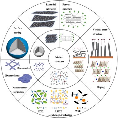
Achieving fast charging of lithium-ion batteries is an effective way to promote the popularity of electric vehicles and solve environmental and energy problems. However, the slow kinetics and increased safety risks of conventional lithium-ion battery systems under fast charging conditions severely hinder the practical application of this technology. This paper reviews the latest research progress in the structural regulation and design of electrode materials and electrolytes for fast-charging lithium-ion batteries. First, we systematically introduce the research progress made in recent years within the scope of improving the diffusion rate of Li-ion in electrode materials by structural modulation of electrode materials. The review focused on optimizing the ion/electron conductivity of the materials and shortening the Li-ion transfer path. Then, we systematically introduce the methods to improve the fast charging performance through the regulation and design of electrolytes, in terms of improving the ion conductivity of electrolytes and regulating Li-ion solvation structure and then highlight the acceleration of Li-ion de-solvation process by regulating the lithium salt concentration and Li-ion solvent interactions with the goal of achieving promotion of Li-ion transfer at the phase interface. Finally, the key scientific issues facing fast-charging Li-ion batteries is summarized as well as the future research directions.

Contents

1 Introduction

2 Electrode materials

2.1 Expanding the material layer spacing

2.2 Nanostructure regulation

2.3 Surface coating

2.4 Porous structure regulation

2.5 Vertical array structure

2.6 Doping

3 Electrolytes

3.1 Low viscosity solvent

3.2 Additive

3.3 Regulating solvation

4 Conclusion and outlook

Cite this article

Disheng Yu , Changlin Liu , Xue Lin , Lizhi Sheng , Lili Jiang . Structural Regulation and Design of Electrode Materials and Electrolytes for Fast-Charging Lithium-Ion Batteries[J]. Progress in Chemistry, 2024 , 36(1) : 132 -144 . DOI: 10.7536/PC230521

1 Introduction

With the deterioration of energy shortage and environmental pollution, it is imperative to reduce the use of fossil fuels. As transportation has always been one of the largest fossil fuel demanders in modern society, the use of clean energy provides an important way to solve energy shortage and environmental pollution[1]. In recent years, electric vehicles powered by lithium-ion batteries (LIBs) have been rapidly developed in terms of energy density, cyclicity, safety, and cost control. However, compared with fuel vehicles, the charging time of electric vehicles is longer, which limits their further market promotion[2,3]. Therefore, solving the problem of fast charging is the threshold that the development of electric vehicles must cross. The US Department of Energy proposes to charge 80% of the rated charge in 10 minutes at 6 C, which is called extreme fast charging (XFC), aiming to provide electric vehicles with a charging experience similar to refueling of fuel vehicles[4]. However, at present, the vast majority of electric vehicles on the market need 2 to 6 hours to be fully charged, which is far from meeting people's requirements for efficient travel[4].
At present, commercial LIBs mainly include graphite anode, transition metal oxide anode and carbonate-based electrolyte. However, this system cannot meet the stringent requirements of LIBs fast charging technology[5,6]. The fast charging performance of LIBs is mainly restricted by the following three aspects: the transport of :(1)Li+ in the electrolyte; The transfer of (2)Li+ at the phase interface (solid electrolyte membrane (SEI) and cathode electrolyte interface (CEI)), including desolvation of Li+, charge transfer and ion migration at the interface; Migration and diffusion of (3)Li+ in electrode materials[7]. The desolvation process of Li+ is considered to be the most energy-consuming step in the fast charging process of LIBs. Due to the presence of the electronically insulating SEI, the charge cannot be transferred immediately after the solvated Li+ reaches the graphite surface. Solvated Li+ must be stripped of its solvation sheath to facilitate the subsequent transport of Li+ in the SEI, and the energy barrier for this process is universally at 50~70 kJ·mol−1[8]. Therefore, the desolvation process of Li+ greatly limits the fast charging performance of LIBs. Under fast charging conditions, LIBs may also have a series of side reactions, which affect the performance and safety of batteries. LIBs can continuously rupture and rebuild the SEI during fast charging, which can lead to a decrease in the coulombic efficiency of the battery and a safety problem caused by a rapid increase in the internal temperature of the battery[9]. In addition, the lithium intercalation potential of the negative electrode, when approaching the electrode potential (0 V vs Li/Li+) of lithium metal, causes the Li+ not to be intercalated into the negative electrode material but to exist in the form of precipitated lithium metal. The lithium intercalation potential of the negative electrode decreases faster at high rates, resulting in lithium evolution at lower States of charge[10~12]. The precipitated lithium metal will continue to react with the electrolyte and consume the electrolyte, thus damaging the electrochemical performance of the battery[13]. In addition, the precipitated lithium metal may grow continuously in the form of dendrites during the charge-discharge cycle, which can pierce the separator, cause internal short circuit of the battery, and cause safety problems such as fire or explosion[14,15]. Therefore, the electrode materials and electrolyte of LIBs must be optimized and improved to meet the needs of fast charging technology.
In this review, the latest research progress of fast-charging LIBs is summarized from the aspects of electrode materials and electrolytes. First, the strategies to improve the fast charge performance by adjusting and designing the structure of electrode materials are introduced, including optimizing the ionic/electronic conductivity of materials and shortening the Li+ transfer path. Secondly, the strategies to improve the fast charging performance by controlling and designing the solvation structure of Li+ in electrolyte are discussed, and the improvement of ionic conductivity of electrolyte and the construction of special solvation structure of Li+ are reviewed.It is emphasized that the desolvation process of Li+ can be accelerated by adjusting the concentration of lithium salt and the interaction between Li+ and solvent, so as to promote the transfer of Li+ at the phase interface. Finally, the key scientific problems faced by fast-charging LIBs are summarized and the future research directions are prospected.

2 Electrode material

For electrode materials, the ideas to achieve fast charge are as follows: (1) to improve the ionic and electronic conductivity of materials, promote Li+ and charge transfer; (2) shortening the diffusion path of the Li+ inside the electrode material; And (3) that negative electrode is prevent from separating lithium, and the safety performance is ensure. Therefore, the common effective strategy is to optimize the structure of electrode materials, including designing electrode materials with high ionic/electronic conductivity by coating or doping, and shortening the diffusion path of Li+ by nano-designing materials and reducing the interlayer spacing of materials.

2.1 Layer spacing control

Too large or too small interlayer spacing of electrode materials will lead to the increase of diffusion resistance of Li+, which is not conducive to the rapid diffusion of Li+. Therefore, the rate capability of LIBs can be improved by properly adjusting the interlayer spacing of electrode materials. Xu et al. Prepared new recycled graphite (N-RG) from acid-treated waste graphite by one-step vapor exfoliation and nitrogen doping[16]. The interlayer spacing of N-RG is enlarged from 0.337 nm to 0.348 nm (Figure 1A). The enlarged layer spacing can provide a wider channel for the transmission of Li+, thus improving the fast charging performance of LIBs. Meanwhile, the nitrogen configuration and content of N-RG are 42.28% pyridine nitrogen, 54.37% pyrrole nitrogen and 3.35% graphite nitrogen. Pyridine nitrogen and pyrrole nitrogen are mainly located at the defect sites or edges of the graphene plane (Figure 1B), which are very active for the adsorption of Li+ and help to improve the Li+storage capacity of the material. The LiFePO4/N-RG full cell has a capacity of 111.3 mAh·g−1 at 4 C (Figure 1C). In addition, Kim et al. Prepared expanded graphite with expanded interlayer spacing (0.3359 nm increased to 0.3390 nm) under mild conditions[17]. Enlarging the interlayer spacing is to improve the diffusion kinetics of ions by widening the transport space of Li+. The activation energy of Li+ intercalation is significantly reduced due to the introduction of a variety of functional groups into the expanded graphite, which can form hydrogen bonds with carbonate solvent molecules in the electrolyte. Therefore, the capacity of the half-cell using expanded graphite as the negative electrode is 243 mAh·g−1 at 50 C, while the pristine graphite is only 66 mAh·g−1. Jiang et al. Synthesized a selenium disulfide/graphene/selenium disulfide (SnS2/rGO/SnS2) composite by a simple one-step hydrothermal method, which expanded the interlayer spacing of SnS2 to ~ 8.2323 Å[18]. The enlarged interlayer spacing and the uniform distribution of a large number of ultrafine SnS2 nanoparticles on the surface of the graphene sheet can promote the rapid intercalation/deintercalation of Li+, thereby accelerating the transport kinetics. Therefore, SnS2/rGO/SnS2 exhibits an excellent rate capability (capacity of 844 mAh·g−1) at a current density of 10 A·g−1.
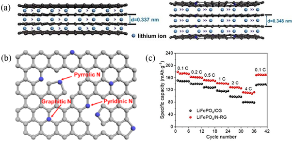
图1 (a) 废旧石墨和N-RG中Li+扩散路径的示意图;(b)N-RG中氮的结合条件结构示意图;(c) LiFePO4/N-RG全电池和LiFePO4/商用石墨全电池的倍率性能[16]

Fig. 1 (a) Schematic diagrams of Li+ diffusion path in CG and N-RG; (b) Schematic structure of the binding conditions of N in N-RG; (c) Rate performance of the LiFePO4/N-RG full cell and LiFePO4/CG full cell[16]. Copyright 2022, Elsevier

To sum up, too small interlayer spacing will lead to slow intercalation of Li+, while too large interlayer spacing will lead to too much electrolyte immersion, resulting in the formation of a thick SEI layer, thus limiting the transmission of Li+. Therefore, by adjusting the optimal interlayer spacing of the electrode material, the Li+ can diffuse in the electrode material at the fastest speed to realize the fast charging of LIBs.

2.2 Nanocrystalline structure design

The small particle size brought by nanostructure can shorten the diffusion distance of Li+, improve the intercalation and deintercalation kinetics of Li+ in electrode materials, and increase the electron transfer speed to some extent[19]. At the same time, the contact area between the electrode material and the electrolyte increases due to the nanocrystallization, which is beneficial to the rapid diffusion of Li+ at the electrode/electrolyte interface[20]. Therefore, the nano-structure design of materials is one of the effective ways to improve the rate capability of electrode materials.
The nanostructure of electrode materials can be divided into zero-dimensional nanostructure, one-dimensional nanostructure and two-dimensional nanostructure according to the dimensionality of the material. Zero-dimensional nanostructures have a large specific surface area, but they usually exhibit low thermal and electrochemical stability. The specific surface area and porosity of one-dimensional nanostructures are difficult to adjust in a wide range. However, two-dimensional nanostructures usually have large specific surface area and unique sheet-like structure. Due to the sheet-like nature of 2D nanostructures, it is much easier to design their structure and porosity. Therefore, the specific surface area and porosity of two-dimensional nanostructures can be adjusted in different ways. Therefore, compared with zero-dimensional nanostructures and one-dimensional nanostructures, two-dimensional nanostructures with high stability, short Li+ diffusion distance and large specific surface area are more suitable for fast-filling LIBs[21,22]. Wang et al. Prepared ultrathin mesoporous Li4Ti5O12 nanosheets by combining a simple solvothermal reaction with a calcination process[23]. First, the ultrathin nanosheet with an average thickness of about 1 nm shortens the transport path of Li+ and electrons in the direction perpendicular to the surface of the nanosheet. Secondly, the uniform mesoporous structure can make the electrolyte penetrate into the active material, reduce the concentration polarization and improve the rate performance of LIBs. Finally, Li4Ti5O12 with a large specific surface area (181.7 m2·g−1) can provide more effective active sites for Li+ storage, thereby improving the specific capacity and rate capability. Therefore, the Li4Ti5O12 nanosheets exhibit excellent cycling stability (95% capacity retention after 2500 cycles at 20 C) and remarkable rate capability (145 mAh·g−1) capacity at 50 C). In addition to the nanostructure mechanism mentioned above, there is a special statement in LiFePO4. The Li+ in the LiFePO4 can only diffuse along the [010] direction. Therefore, Zhao et al. Shortened the diffusion distance of Li+ and increased the specific surface area of the active material by preparing LiFePO4 nanosheets with nanometer thickness in the [010] direction (Figure 2A)[24]. The LiFePO4 nanosheets have a capacity of 55 mAh·g−1 at 30 C (Figure 2B).
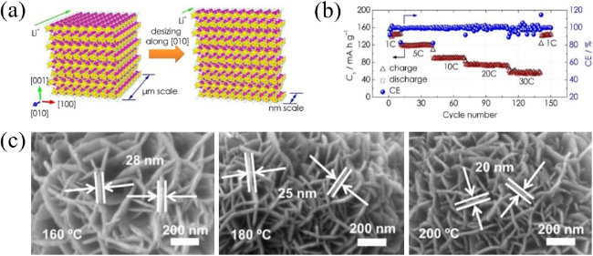
图2 (a)沿[010]缩短Li+扩散距离的示意图;(b)1~30 C范围内的倍率性能[24];(c)U-LTO-NHMS的SEM图像[25]

Fig. 2 (a) Schematic illustration of shortening the lithium-ion diffusion distance along the [010]; (b) Rate capability at the C-rate ranging from 1~30 C[24]. Copyright 2019, American Chemical Society; (c) SEM images of U-LTO-NHMS[25]. Copyright 2019, American Elsevier

Nanostructures have undeniable advantages in improving rate capability, but nanostructured materials usually have low tap density, which leads to a sharp decline in the volume energy density of electrode materials. Chen et al. Prepared a layered microsphere electrode material based on Li4Ti5O12 nanosheets (U-LTO-NHMS) that can simultaneously achieve high tap density (1.32 g·cm−3) and high rate performance[25]. U-LTO-NHMS was prepared by a simple solvothermal reaction followed by a brief thermal annealing treatment. The tap density can be controlled by changing the solvothermal reaction temperature, thereby changing the size of the secondary particle. As shown in Figure 2C, the solvothermal reaction has the largest secondary particle size at 160 ° C (U-LTO-NHMS-160), resulting in a higher tap density. Meanwhile, U-LTO-NHM S-160 also has moderate specific surface area (67.03 m2·g−1) and uniform mesoporous structure. The moderate specific surface area can provide more effective active sites for Li+storage, and the uniform mesoporous structure can reduce the concentration polarization. Therefore, U-LTO-NHMS-160 can improve the cycling performance (99.5% capacity retention after 2000 cycles at 50 C) and rate capability (155 mAh·g−1 capacity at 50 C) of LIBs.

2.3 Cladding

Coating the surface of electrode materials is a commonly used method to construct artificial interface films (SEI and CEI)[26]. The introduction of an artificial interfacial film can physically separate the electrolyte and the electrode material to protect the electrode and provide ideal ionic conductivity. Therefore, the coating layer on the electrode surface can promote the diffusion of Li+.
Carbon materials are often used to coat the surface of electrode materials because of their good conductivity and structural stability[27]. Coating carbon materials on the surface of electrode materials can increase the conductivity of electrode materials and provide rapid Li+ diffusion channels[28]. In addition, as a protective layer, it can prevent the side reaction between the electrode material and the electrolyte[29]. Lyu et al. Synthesized titanium-niobium oxide (TiNb2O7,TNO)@C materials with different thickness of carbon coating using glucose as carbon source[30]. The TNO with carbon coating exhibited better rate performance than the pristine TNO, but the materials with 2 wt% and 3 wt% carbon coating exhibited worse rate performance than the 1 wt% carbon coating material. This indicates that the carbon coating can effectively improve the electronic conductivity of TNO materials, but if the coating is too thick, it will hinder the diffusion of Li+. The 1 wt% carbon-coated TNO material with the best rate capability has a capacity of 240 and 211 mAh·g−1 at 5 and 10 C, respectively. Guan et al. Prepared three-dimensional LiFePO4@C/ graphene composite by solvothermal reaction of LiFePO4@C and graphene oxide with glucose as carbon source[31]. The LiFePO4@C particles are uniformly embedded in the three-dimensional graphene framework, which hinders the stacking phenomenon that graphene oxide is prone to occur during the reduction process. The excellent conductivity of graphene and the sufficient and effective contact between LiFePO4@C and graphene facilitate the rapid transfer of electrons of Li+. Therefore, the composite shows excellent rate capability (capacity of 112.4 and 96.7 mAh·g−1) at 30 and 50 C, respectively.
The addition of inorganic compounds, polymers, and organic/inorganic hybrids other than carbon materials to coat the electrode materials can also suppress the interfacial reaction between the electrode materials and the electrolyte, resulting in thinner and more stable SEI or CEI. Kim et al. Demonstrated that coating graphite with amorphous Al2O3 is one of the effective ways to improve the fast charging ability of LIBs graphite anode materials (Fig. 3A, B)[32]. The introduction of amorphous Al2O3 improves the electrolyte wettability of graphite electrode, which can improve the kinetics of Li+ intercalation. The electrode material has a capacity of 337.1 mAh·g−1 at a current density of 4 A·g−1, corresponding to 97.2% of the capacity at a current density of 100 mA·g−1 (Figure 3C). Ran et al. Successfully prepared the LiNi0.6Co0.2Mn0.2O2−x(PO4)x@Li3PO4-PANI cathode material by combining the doping PO43− and double conductive layer (Li3PO4-PANI) methods (Fig. 3D)[33]. Firstly, the introduction of the double conductive layer can reduce the amount of residual lithium salt on the surface of the LiNi0.6Co0.2Mn0.2O2 cathode, thus inhibiting the side reaction at the electrode/electrolyte interface to some extent. In addition, the double conductive layer can also improve the ionic conductivity of the cathode material. Compared with the original LiNi0.6Co0.2Mn0.2O2(1.53×10⁻⁵S·cm−1), the ionic conductivity of the LiNi0.6Co0.2Mn0.2O2 with the double conductive layer is improved to a 4.7×10⁻⁴S·cm−1. Secondly, gradient doping can replace the original O2− with PO43−( Fig. 3 e). Due to the strong covalent P-O bond and excellent structural stability, the gradient-doped PO43− can achieve the stability of the positive oxygen layer, thereby improving the lattice stability, resulting in better cycling stability of LiNi0.6Co0.2Mn0.2O2−x(PO4)x@Li3PO4-PANI (capacity retention of 76.6% after 100 cycles) as well as excellent rate capability (capacity of 130 mAh·g−1) at 5 C).
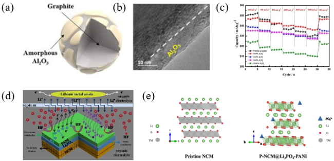
图3 (a) 无定形Al2O3/石墨的结构示意图;(b) 无定形Al2O3/石墨的HR-TEM图;(c) 不同电流密度下的倍率性能[32];(d) 界面改性示意图;(e) 原始LiNi0.6Co0.2Mn0.2O2和P-LiNi0.6Co0.2Mn0.2O2@Li3PO4-PANI的梯度磷酸聚阴离子掺杂示意图和结构模型[33]

Fig. 3 (a) Structural diagram of amorphous Al2O3@graphite. (b) HR-TEM result of amorphous Al2O3@graphite. (c) Rate capabilities at different current densities[32]. Copyright 2019, Elsevier. (d) Schematic diagram of interface modification; (e) Gradient phosphate polyanion doping schematic diagram and structure model for pristine LiNi0.6Co0.2Mn0.2O2 and P- LiNi0.6Co0.2Mn0.2O2@Li3PO4-PANI[33]. Copyright 2019, American Chemical Society

2.4 Pore structure regulation

Porous structure can be formed by etching the electrode material. At present, the main pore-forming methods include oxidation etching, thermal stripping, laser etching and so on. The porous structure can significantly increase the number of active sites for Li+ intercalation/deintercalation and reduce the diffusion distance of Li+ inside the electrode material, thus promoting the rapid diffusion of Li+. Cheng et al. Constructed a graphite with porous structure (Figure 4A) by using KOH to etch the graphite surface, which can increase the number of sites for Li+ intercalation/deintercalation and reduce the diffusion distance of Li+[34]. The capacity retention of KOH-etched graphite and as-received graphite at 3 C is 93% and 85%, respectively. In addition, the capacity retention of KOH-etched graphite at 6 C is still 74%. Kim et al. Modified the original graphite by acid and alkali respectively (Fig. 4B)[35]. Sulfuric acid/nitric acid can oxidize graphite, thus exfoliating the bulk graphite layer into thin exfoliated graphite. The chemical oxidation process also transforms the hydrophobic original graphite into hydrophilic graphite by introducing — OH groups into the carbon structure, which helps the electrolyte to diffuse into the electrode, thus increasing the rapid transport of Li+ between the graphite layers. The surface of the graphite layer etched by KOH will form a large number of pores, which will promote the diffusion of Li+ and increase the number of Li+ intercalation sites in the graphite layer. The capacity of acid and alkali treated graphite at a current density of 1.5 A·g−1 (95 and 93 mAh·g−1) is better than that of pristine graphite (50 mAh·g−1). Chen et al. Created a large number of micropores on the surface of graphite negative electrode by laser etching technology to help the rapid diffusion of Li+ in the thick electrode (Fig. 4C)[36]. Making a large number of micropores on the surface of the negative electrode can effectively accelerate the diffusion of Li+ in the electrode, reduce the polarization of the negative electrode during charging, and avoid lithium precipitation from the negative electrode, thus significantly improving the cycle life under fast charging. The capacity retention of the laser-etched graphite anode is 93% and 56% after 100 and 600 cycles at 6 C, respectively, which is much higher than that of the pristine graphite anode.
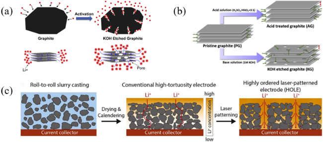
图4 (a)石墨和KOH刻蚀石墨的示意图[34];(b)制备酸处理石墨和KOH刻蚀石墨示意图[35];(c)负极制造工艺示意图[36]

Fig. 4 (a) Schematic scheme of pristine graphite and KOH etched graphite[34]. Copyright 2015, Elsevier. (b) Schematic illustration of the preparation of acid treated graphite and KOH-etched graphite[35]. Copyright 2020, Elsevier. (c) Schematic illustration of anode fabrication processes[36]. Copyright 2020, Elsevier

2.5 Vertical array structure

In addition to improving the internal ion transport by adjusting the electrode material structure, the external ion transport can also be enhanced by the structural design of the counter electrode. The vertical array structure can control the orientation of the electrode in a specific direction and reduce the tortuosity of the diffusion path of Li+ inside the electrode, thus effectively accelerating the diffusion of Li+ in the electrode. Billaud et al. Regulated the orientation of graphite by applying a magnetic field formed by an external current to make it grow vertically on the current collector[37]. This method reduces the tortuosity of the graphite electrode and shortens the diffusion path of Li+ on the electrode, resulting in excellent rate performance under ultra-high loading of (10 mg·cm−2). Guo et al. Used the freeze-coating technique to study the microstructure and electrochemical performance of LiFePO4 electrodes at different solid contents and freezing rates[38]. The electrode fabricated by the freeze-coating technique can improve the electron transfer and Li+ diffusion rate of the LiFePO4 electrode due to the vertically interconnected solid network (Figure 5A). The LiFePO4 electrode fabricated when the solid content is 30 wt% and the freezing time is 5℃·min−1 has the highest Li+ diffusion coefficient (1.32×10⁻¹²cm−2·s−1) and the highest conductivity (3.1×10⁻³S·cm−1). Therefore, the capacity of the LiFePO4 electrode fabricated by the freeze-coating technique is 40.7 mAh·g−1 at 15 C, while the capacity of the LiFePO4 electrode fabricated by the conventional coating technique decays to a negligible level at 15 C (Figure 5B). Tu et al. Proposed an electrode structure consisting of a large-scale monolayer of particles with vertically aligned carrier transport channels[39]. Monolayer particle electrodes have continuous, short and straight ion and electron transport paths (fig. 5C), high electrode density, and low electrolyte intake (fig. 5d, e) compared to conventional particle electrodes. In addition, the contact resistance of the monolayer particle electrode in the direction of ion transport is smaller, so its overpotential is smaller. Therefore, the monolayer particle electrode has a unique advantage for LIBs to achieve fast charging.
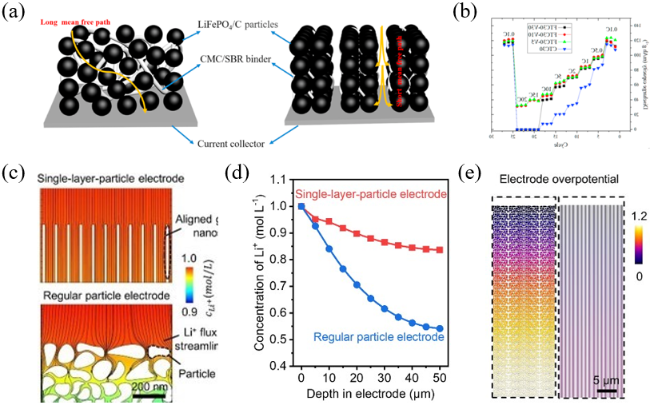
图5 (a)由常规涂敷技术制造的含有曲折多孔网络的随机电极结构和由冷冻涂敷技术制造的含有垂直阵列的定向电极结构;(b)冷冻涂敷技术制造的不同固体含量电极的倍率性能[38];(c)电解液中的Li+浓度;(d)电解液中的Li+浓度分布;(e)电解中的电极过电位[39]

Fig. 5 (a) Random electrode microstructure containing a tortuous porous network made by CTC directional electrode microstructure with vertical pore arrays made by FTC. (b) Rate performance of the FTC electrodes with different solid content[38]. Copyright 2021, Elsevier. (c) Li+ concentration in electrolyte. (d) Li+ concentration distribution in electrolyte. (e) Electrode overpotential in electrolyte[39]. Copyright 2022, Wiley Blackwell

2.6 Doping

Doping generally improves the electron conductivity by controlling the non-stoichiometric ratio to create new electrons or holes[40]. Therefore, the diffusion rate of Li+ can be improved by doping atoms or ions in the electrode materials. Dopant atoms in electrode materials can introduce more defects and active sites for the intercalation of Li+, thereby improving the storage capacity of Li+. For example, the incorporation of nitrogen atoms in the carbon structure can introduce more active sites and facilitate charge transfer, thereby significantly improving the storage capacity of Li+[41]. In addition, doping atoms can also improve the conductivity of electrode materials, thus promoting the transfer of electrons and ions. Wang et al. Used tricresyl phosphate as a phosphorus source, oligomeric phenolic resin as a carbon source, and triblock copolymer F127 as a soft template to induce the co-assembly of ternary components on the polyurethane sponge skeleton through solvent evaporation to prepare large-pore phosphorus-doped mesoporous carbon[42]. Phosphorus doping can improve the electronic conductivity and enlarge the interlayer spacing of mesoporous carbon, which is beneficial to the rapid transfer of electrons and the intercalation/deintercalation of Li+. In addition, phosphorus doping can also introduce more defects in the carbon skeleton to provide more active sites for the storage of Li+. The large-pore phosphorus-doped mesoporous carbon can not only maintain the capacity of 236 mAh·g−1 at 8 C, but also provide long-term cycling stability.
Doping ions in electrode materials can adjust the electronic structure and optimize the electronic conductivity of electrode materials by narrowing the band gap and creating local defects. In addition, the doping ions can also create more active sites for the intercalation of Li+. Tu et al. Improved the fast charging performance of Ti2Nb10O29(TNO) by combining doping ions and spiral array structure[43]. Firstly, a novel porous vertical graphene @ TiC-C array (VGTC) framework was designed as a conductive matrix. VGTC has excellent mechanical stability and high ionic/electronic conduction properties. Then, the spiral growth of Cr3+ doped TNO nanoparticles (Cr-TNO) was realized on the VGTC framework, forming Cr-TNO @ VGTC arrays (Figure 6A). By density functional theory calculations, Li+ presents an energy barrier of 0.8 eV in Cr-TNO (3.6 eV in TNO and 1.6 eV in nanosized TNO), indicating the faster reaction kinetics of Cr3+ doped TNO. In addition, the conductivity of Cr-TNO is significantly enhanced due to the presence of an impurity level between the valence and conduction bands. Density functional theory calculations proved the improvement of both conductivity and ion transfer of Cr3+ doped TNO. Therefore, the Cr-TNO @ VGTC array has a capacity of 220 mAh·g−1 at 40 C. Wu et al. Synthesized Li0.99K0.01V0.995Zr0.005PO4F/C composite (K1Zr0.5 by double ion doping of K+ and Zr4+ on lithium vanadium fluorophosphate (LiVPO4F) materials[44]; Fig. 6 B). The Hall effect shows that Zr4+ doping changes the conductivity type of LiVPO4F materials from P-type semiconductor to N-type semiconductor, and the conductivity increases by 104 times, thus making the conductivity reach the 1.2×10⁻²S·cm−1. The ionic radii of K+ and Zr4+ are larger than those of Li+ and V3+,Therefore, the doping of Zr4+ and K+ will expand the unit cell volume of LiVPO4F.It leads to the expansion of the diffusion path of Li+, which promotes the diffusion coefficient (9.83×10⁻¹³cm−2·s−1) of Li+. The capacity of the K1Zr0.5 at 60 C can still reach the 105.7 mAh·g−1. Meanwhile, the capacity retention after 2000 cycles at 10 C was 80% (Fig. 6 C).
图6 (a) Cr-TNO@VGTC的EDS元素映射图像:Ti, Nb, O, Cr和C[43];(b)K1Zr0.5的EDS;(c)K1Zr0.5的电化学性能[44]

Fig. 6 (a) EDS elemental mapping images of Cr-TNO@VGTC[43]. Copyright 2020, Wiley VCH Verlag. (b) The EDS of K1Zr0.5. (c) The Electrochemical performance of K1Zr0.5[44]. Copyright 2018, Elsevier

3 Electrolyte

The transport speed of solvated Li+ in the electrolyte and the activation energy of desolvation at the electrolyte-SEI interface, as well as the migration speed of Li+ through the SEI, are all important factors determining the fast charging performance of LIBs[4]. Therefore, the electrolyte should have high ionic conductivity to ensure the rapid diffusion of Li+ in the electrolyte. Second, the SEI must be structurally stable, thin and robust, and have excellent ionic conductivity. Finally, the lower activation energy of Li+ desolvation can accelerate the desolvation process at the electrolyte-SEI interface. The composition of the electrolyte plays an important role in the ionic conductivity, the composition and structure of the SEI, and the activation energy of desolvation and migration velocity of Li+ through the SEI[45]. Therefore, it is necessary to develop an electrolyte formula suitable for fast charging requirements.

3.1 Low concentration main solvent

Generally speaking, the index to quantify the transport ability of Li+ in electrolyte is the ionic conductivity of electrolyte[46]. The low ionic conductivity of the electrolyte will cause the transport of Li+ in the electrolyte to be hindered, thus affecting the fast charging performance. The most effective way to improve the ionic conductivity of the electrolyte is to replace all or part of the main solvent with a solvent with low viscosity and high dielectric constant. For example, butyronitrile solvent can fully dissolve lithium salt due to its high dielectric constant, so it can improve the ionic conductivity of the electrolyte as the main solvent of the electrolyte[47]. In addition, Logan et al. Prepared lithium hexafluorophosphate (LiPF6) an ester-based electrolyte dissolved in methyl acetate (MA), which was greatly improved in ion transport[48]. MA has a low viscosity and a higher dielectric constant than traditional carbonate-based solvents, which greatly improves the transport characteristics of the electrolyte. At a salt concentration of 2 mol·kg−1, the ionic conductivity of MA/LiPF6 is 25 mS·cm−1, which is twice the ionic conductivity of the ethylene carbonate (EC)/dimethyl carbonate (DMC)/LiPF6 electrolyte system. Therefore, at this salt concentration, the capacity retention of MA/LiPF6 electrolyte at 4 C is 65%, while that of EC/DMC/LiPF6 electrolyte is only 20%. Gao et al. Solved the problem of short cycle life of LIBs under extreme fast charge conditions by designing a novel ester-based electrolyte (1 M LiPF6 dissolved in methyl propionate (MP) + 10% fluoroacetate (FEC) (M9F1))[49]. First, the lower viscosity of the MP solvent enables the M9F1 electrolyte to increase the ionic conductivity to 12.1 mS·cm−1( Fig. 7A) and also increase the ionic transference number to 0.46. Secondly, the interface thickness formed by M9F1 electrolyte after 1000 cycles is thinner than that of conventional electrolyte (Fig. 7B). In addition, the SEI formed in M9F1 exhibited a higher LiF/LixPFy ratio, indicating the formation of a stable SEI rich in LiF. A lower ROCO2Li/Li2CO3 ratio was also found in M9F1, which is generally considered to be more favorable for Li+ diffusion in the SEI. Finally, the activation energy for desolvation of M9F1 electrolyte is about 5 kcal·mol−1, while that of conventional electrolyte exceeds 7 kcal·mol−1. The lower activation energy of M9F1 electrolyte is more favorable for charge transfer. As a result, the battery using M9F1 showed 88.2% and 77.9% capacity retention after 500 and 1000 cycles at 4 C charge (Figure 7 C), compared to 54.1% and 12.4% for the battery using EC/ethyl methyl carbonate (EMC) electrolyte (Figure 7 d).
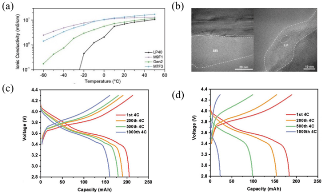
图7 (a)离子导率;(b)在常规电解液和M9F1中循环1000次后石墨表面的低温TEM图像;(c)M9F1电解液的电池在4 C恒流循环期间的电压曲线;(d)常规电解液(1.2 M LiPF6 EC/EMC(3:7))的电池在4 C恒流循环期间的电压曲线[49]

Fig. 7 (a) Ionic conductivity; (b) Cryo-TEM images of the graphite surface after 1000 cycles in Gen2 and M9F1; (c) Voltage profiles over 4 C constant current cycling duration in M9F1; (d) Voltage profiles over 4 C constant current cycling duration in Gen2[49]. Copyright 2022, Wiley VCH Verlag

3.2 Additive

The interfacial films (SEI and CEI) that meet the requirements of fast charging should have high ionic conductivity, suitable thickness, extremely high uniformity, ideal mechanical strength, and outstanding chemical/structural stability[50]. The interfacial film derived from conventional electrolyte is mainly composed of organic oligomers generated by EC reduction. The interface film has fewer grain boundaries than interface films mainly composed of inorganic components such as lithium nitride (Li3N), lithium fluoride (LiF), lithium oxide (Li2O), and the like. The energy barrier of Li+ diffusion through grain boundary is lower and the migration speed is faster[51]. Therefore, the transport of Li+ through the organic-dominated interfacial film can be hindered at high current, resulting in a significant increase in the interfacial resistance. Moreover, this interfacial film is sensitive to temperature. Compared with normal rate charging, fast charging leads to an increase in internal temperature, which accelerates electrolyte decomposition and increases the thickness of the interfacial film, which increases the energy barrier for Li+ to cross the interfacial film. The electrolyte film forming additive has a lower reduction potential than EC, and can be reduced and decomposed before EC to form an interfacial film. Therefore, by selecting a small proportion of electrolyte film-forming additives, the interface film mainly composed of organic matter can be changed into an interface film mainly composed of inorganic matter, thus improving the fast charging performance of lithium-ion batteries. Shi et al. Dissolved 1 mol·L−1LiPF6 in EC and DMC and added fluorosulfonyl isocyanate (FI) to improve the fast charging performance of LIBs[52]. Compared with EC and DMC, FI has a lower lowest unoccupied molecular orbital, which can make FI reduce before EC and DMC. FI forms SEI on the graphite surface, which is mainly composed of inorganic components, which can make the impedance at the graphite/electrolyte interface lower, thus promoting the rapid diffusion of Li+.
The diffusion rate of Li+ in the CEI on the cathode surface also affects the fast charging performance of LIBs. Cheng et al. added lithium bisoxalatoborate (LiBOB) and dopamine (DA) to the traditional carbonate-based electrolyte to form an organic/inorganic composite CEI on the surface of the cathode (Figure 8 a)[53]. The internal cracks of the LiNi0.8Co0.1Mn0.1O2 will cause the continuous penetration of the electrolyte, and the reaction between the electrolyte and the new interface will lead to a sharp decline in capacity. However, the electrolyte containing LiBOB and DA can well improve this problem, which will form a uniform and stable CEI on the surface of the positive electrode, and there will be no obvious cracks in the LiNi0.8Co0.1Mn0.1O2 during cycling. In addition, nitrogen-rich LiBOB and DA-derived CEI have lower impedance. Because nitrogen has a high affinity for Li+, it can promote the diffusion of Li+. LiBOB and DA-derived CEI can not only improve the cycle stability of LIBs, but also improve the rate capability. The capacity of the Li||LiNi0.8Co0.1Mn0.1O2 cell using this electrolyte was 96 and 51 mAh·g−1( at 10 and 20 C, respectively Fig. 8 B). Wang et al. Reported the ester-based electrolyte (1 mol·L−1LiPF6FEC/EMC-LiBF4(2%)-LiNO3(2%)) with lithium tetrafluoroborate (LiBF4) and lithium nitrate (LiNO3) as additives[54]. The electrolyte can not only form a stable SEI on the negative electrode, but also enhance the reversibility of Li+ intercalation/deintercalation. At the same time, the thin and strong CEI formed by the electrolyte can avoid the continuous side reaction from the electrolyte and maintain the structural integrity of the LiNi0.8Co0.1Mn0.1O2. In addition, LiBF4 can promote the dissolution of LiNO3 in traditional carbonate solvents through its unique steric structure and Lewis acidity. The introduction of LiNO3 additive makes both SEI and CEI rich in lithium nitride compounds with fast ion transport characteristics, thus promoting the transport of Li+ at the interface between the positive and negative electrodes. The electrolyte based on this design enables the Li||LiNi0.8Co0.1Mn0.1O2 cell to have a 185.6 mAh·g−1 capacity at 5 C.
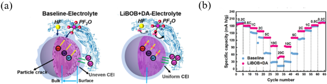
图8 (a) 在富镍LiNi0.8Co0.1Mn0.1O2正极中使用和不使用LiBOB和DA添加剂形成的均匀和损坏的CEI示意图;(b) 常规电解液(1.1 mol·L−1 LiPF6 EC/DEC(1:1))和LiBOB+DA电解液半电池的倍率性能[53]

Fig. 8 (a) Schematic illustration of uniform and damaged CEI formed in nickel-rich LiNi0.8Co0.1Mn0.1O2 cathode with and without LiBOB+DA additives; (b) Rate performance of conventional electrolyte (1.1 mol·L−1 LiPF6 EC/DEC(1:1)) and LiBOB+DA [53]. Copyright 2021, Elsevier BV

3.3 Solvation structure control

Salt concentration is a key factor in determining the solvation structure of Li+. As the salt concentration increases, fewer solvent molecules are available to occupy the solvation sheath due to the decrease in solvent molecules, allowing anions to enter the solvation sheath to interact with the Li+[55]. The solvated structure also changes from the original coordination of Li+ and solvent molecules to contact ion pairs (CIPs) with one anion coordinated to one Li+ or aggregates (AGGs) with one anion coordinated to two Li+; Fig. 9 a)[56].
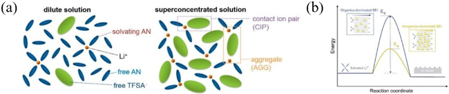
图9 (a)常规低浓度电解液和高浓度电解液中Li+的配位 [56];(b)降低Li+去溶剂化和在SEI中扩散的活化能(Ea[63]

Fig. 9 (a) Representative environment of Li+ in a conventional dilute solution and salt-superconcentrated solution[56]. Copyright 2014, American Chemical Society. (b) Reduced activation energy (Ea) for Li+ desolvation and diffusion across an SEI[63]. Copyright 2020, Elsevier

Aggregation of anions in the solvated structure of Li+ can form an anion-derived SEI. The decomposition of anions can produce inorganic components such as LiF, Li3N, lithium sulfide (Li2S), Li2O[57]. These inorganic components usually have smaller band gaps and higher mechanical hardness, which can lead to excellent performance of inorganic-rich SEI[58,59]. LiF-rich SEI has high chemical/electrochemical stability, which can simultaneously inhibit the continuous decomposition of electrolyte and the growth of lithium dendrite[60]. Secondly, Li3N is considered to be a favorable SEI component for passivating the interface and accelerating the interfacial dynamics because of its high ionic conductivity (~10−3S·cm−1[61]. Synergistic effect of these characteristics, the anion-derived SEI has higher interfacial stability and faster interfacial dynamics at relatively thin thickness. The inorganic component makes the SEI have the beneficial characteristics mentioned above, but the rich inorganic component reduces the organic component in the SEI, and the organic component can buffer the volume change of the electrode material to maintain the integrity of the interface. Therefore, excessive inorganic components can make the SEI unable to adapt to the volume change of electrode materials, resulting in the continuous growth of SEI and the reduction of reversible capacity[62]. Based on a systematic analysis of the interfacial dynamics in the model system, it was found that the solvated structure composed of an anion with Li+ has a lower activation energy for desolvation, and the inorganic-rich anion-derived SEI formed from this solvated structure has a lower activation energy for Li+ diffusion in the SEI (Fig. 9 B)[63]. In addition, the reduction of SEI thickness also contributes to accelerating the kinetics of interfacial transport. The favorable characteristics of the solvated structure composed of anions and Li+ fundamentally ensure the fast charging performance and cycling stability of LIBs.

3.3.1 High concentration electrolyte

A highly concentrated electrolyte is formed when the salt concentration exceeds a threshold value (usually >3~5 mol·L−1, depending on the combination of salt and solvent). Although the high concentration electrolyte sacrifices the viscosity and ionic conductivity of the electrolyte to a certain extent, the anion-derived SEI formed by the high concentration electrolyte can minimize the adverse effects, thus improving the fast charging performance of LIBs[55]. Yamada et al. Found that the prepared 4.2 mol·L−1LiFSA/ acetonitrile (AN) high concentration electrolyte has fast charging characteristics[56]. AN has higher ionic conductivity, and high concentration electrolyte has smaller activation energy of Li+ desolvation. Therefore, the LiFSA/AN high-concentration electrolyte shows a higher capacity than the carbonate-based electrolyte at all rates, especially at 5 C, the high-concentration electrolyte has a capacity of 260 mAh·g−1, while the carbonate-based electrolyte has a capacity of 40 mAh·g−1. The research group also found that the high concentration electrolyte of 3.6 mol·L−1LiN(SO2F)2(LiFSA)/DMC has an ultrafast intercalation speed of Li+ into graphite. This may be because the system has a lower activation energy for Li+ desolvation, which accelerates Li+ intercalation and enhances the Li+ transfer number. The Li | graphite half cell with this electrolyte has a capacity of 90 mAh·g−1 at 5 C[64].

3.3.2 Local high concentration electrolyte

The high viscosity and high cost of high concentration electrolyte are the limiting factors in practical application[65]. The local high-concentration electrolyte can be diluted by adding an inert low-viscosity diluent which does not participate in the solvation structure into the high-concentration electrolyte, so as to reduce the concentration and viscosity of the electrolyte while retaining the solvation structure of the high-concentration electrolyte[66]. The inert diluent introduced shall have the following strict requirements: (1) low viscosity; (2) low cost; (3) proper dielectric constant and coordination ability; (4) being electrochemically inert in the working voltage range of LIBs; (5) Non-flammable and low volatilization. Various perfluorinated diluent molecules, including Tris (2,2,2-trifluoroethyl) orthoformate (TFEO), 1,1,2,2-tetrafluoroethyl-2,2,3,3-tetrafluoropropyl ether (TTE), bis (2,2,2-trifluoroethyl) ether (BTFE), fluorobenzene (FB), etc., have been used as diluents for localized high-concentration electrolytes in order to reduce the electrolyte viscosity while maintaining the Li+ solvation structure of high-concentration electrolytes. Jiang et al. Used lithium bis (fluorosulfonyl) imide (LiFSI) as the lithium salt, 1,2-dimethoxyethane (DME) as the solvent and BTFE as the diluent to prepare a local high concentration electrolyte of 1.5 mol·L−1LiFSI DME/BTFE, which demonstrated the fast charging ability of graphite anode to a certain extent[67]. The local high-concentration electrolyte can form a uniform SEI dominated by inorganic components on the graphite surface through the preferential decomposition of anions (Fig. 10a). The inorganic-rich SEI has a lower activation energy for the diffusion of Li+ in the SEI, and the solvated structure composed of FSI and Li+ has a lower activation energy for desolvation. Therefore, the Li | graphite half-cell exhibits a capacity of 220 mAh·g−1 at 4 C (Fig. 10 B).
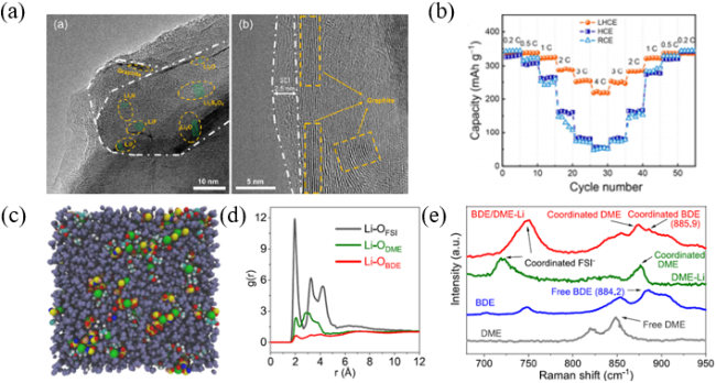
图10 (a)石墨负极上的无机化合物;(b)石墨负极上的SEI膜;(c)Li|石墨半电池的倍率性能[67];(d)分子动力学模拟的1.4 mol·L−1 LiFSI在BDE/DME电解液中的结构;(e)根据模拟轨迹计算出的Li-OBDE、Li-ODME和Li-OFSI的径向分布函数;(f)BDE/DME电解液的拉曼光谱[68]

Fig. 10 (a) The inorganic compounds on graphite anode. (b) The SEI attached on graphite layer. (c) Rate capability for lithium of graphite[67]. Copyright 2020, John Wiley and Sons Ltd. (d) MD simulated electrolyte structure of 1.4 mol·L−1 LiFSI in BDE/DME. (e) Redial distribution functions of Li-OBDE、Li-ODME、Li-OFSI pairs calculated from MD simulation trajectories. (f) Raman spectra of BDE/DME electrolyte[68]. Copyright 2022, Elsevier BV

The diluent in the local high concentration electrolyte has no coordination effect on the Li+, so that the conductivity of the local high concentration electrolyte is generally low. Therefore, the development of diluents that reduce the overall viscosity of electrolyte and participate in the solvation of Li+ through weak coordination interaction can solve the application of LIBs in local high concentration electrolyte under high rate conditions[69]. Deng et al. Prepared a bifunctional fluorinated cosolvent (2,2-difluoroethyl) ether (BDE) as a diluent for local high-concentration electrolyte for high-rate lithium metal batteries[68]. First, from the MD simulation of BDE/DME electrolyte, it can be found that most DME molecules and FSI coordinate with Li+ to form the first solvation sheath, while a large amount of BDE is distributed around the Li+-DME-FSI complex (Figure 10 C). This is similar to most localized high concentration electrolyte cases. Then, calculating the radial distribution function of Li-OFSI, Li-ODME, Li-OBDE using the simulated trajectory can find the existence of Li-OBDE( at 2.0 A Fig. 10 d). At the same time, it can be found from the Raman spectrum that the peak value is shifted after BDE is co-dissolved with LiFSI and DME (Fig. 10e). Therefore, it is confirmed that BDE not only acts as a diluent in the prepared electrolyte, but also participates in the construction of the first solvation sheath of the Li+, which is beneficial to the construction of a more stable SEI while improving the conductivity of the electrolyte.

3.3.3 Weakly solvated electrolyte

In addition to bringing anions into the solvation sheath by increasing the salt concentration, anions can also be forced into the solvation sheath by tailoring the intrinsic solvating power of the solvent. Because solvent and anion enter the solvation sheath of Li+ through competitive coordination, reducing the solvation ability of solvent can make more anions coordinate with Li+. The weak solvating electrolyte is to form the solvated structure of CIPs and AGGs at low salt concentration by using solvents with ultra-low solvating power. Yao et al. Reported a weakly solvated electrolyte composed of 1.0 mol·L−1LiFSI and 1,4-dioxane (1,4-DX)[70]. The change in binding energy between Li+ and solvent molecules and anions was obtained by first-principles calculations. The relative binding energy (defined as the difference between the binding energies of the Li+- solvent and the Li+- anion, ES-EA) is the largest in 1,4-DX (Figure 11 A), which indicates that the anion is dominant in competitive coordination with Li+. Thus, it can be preferentially decomposed to form anion-derived SEI. The excellent rate performance of the weak solvated electrolyte results from its solvated structure, which can accelerate the desolvation process of Li+, and the anion-derived inorganic-rich SEI, which can accelerate the diffusion of Li+ in the SEI, still has 54% capacity retention at 4 C. Sun et al. Designed 1.8 mol·L−1LiFSI weakly solvated electrolyte dissolved in 1,3-dioxane (DOL)[71]. LiFSI was chosen as the lithium salt because it has the best dissociation of all salts and is the easiest to form LiF; DOL was chosen as the solvent because it has the lowest activation energy for desolvation. The ring-opened EC, LixPF6, and LiCO3 clusters at the interface of the carbonate-based electrolyte can be found by molecular dynamics simulation of the SEI structure on graphite, indicating that the SEI is generated by the decomposition of EC solvent molecules. Secondly, there is the formation of LiF and LiNxSyOz clusters at the interface of LiFSI/DOL electrolyte without decomposition products of DOL, indicating that FSI is more easily decomposed at the interface (Fig. 11 B). LiF has a smaller band gap and higher chemical/electrochemical stability, so that faster kinetics and prevention of side reactions can be achieved. The LiFSI/DOL electrolyte has a low Li+ desolvation activation energy and the formation of a thin and robust SEI on the graphite surface, so it achieved a capacity of 315 and 180 mAh·g−1 at 20 and 50 C, respectively, in the Li | graphite half cell (Figure 11C).
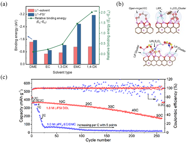
图11 (a) 基于第一性原理计算的Li+与溶剂和阴离子的结合能[70];(b) 分子动力学模拟的石墨和电解液之间的原子SEI结构;(c) 1.8 mol·L−1 LiFSI DOL和1.0 mol·L−1 LiPF6 EC/DMC(1:1体积比)的天然石墨|Li电池的倍率性能[71]

Fig. 11 (a) Binding energy of Li+ with solvents and anions based on DFT calculations[70]. Copyright 2020, John Wiley and Sons Ltd. (b) AMID simulated atomic SEI structure between graphite and electrolytes. (c) Rate performance of NG||Li cell with 1.8 mol·L−1 LiFSI DOL and 1.0 mol·L−1 LiPF6 EC/DMC (1:1 by vol.)[71]. Copyright 2022, Wiley Blackwell

In addition, the weak solvated electrolyte can also be a weak interaction between the cosolvent and the Li+, which weakens the binding energy between the main solvent and the Li+, thereby reducing the desolvation activation energy of the Li+. Xie et al. Designed an electrolyte that can simultaneously achieve rapid diffusion of solvated Li+ in the electrolyte, lower activation energy of Li+ desolvation, and rapid transport of Li+ in the interface[72]. The electrolyte is a weakly solvated electrolyte (LiFSI: AN: FB (1: 2.4: 3) (AN-DHCE)) with fluorobenzene (FB) as a co-solvent and 2.0 mol·L−1LiFSI in AN. AN-DHCE formed a solvated structure dominated by CIPs and AGGs at a high salt-solvent ratio (1: 2.4), which was favorable for the formation of LiF-rich SEI, thus promoting the interfacial transport of Li+. The non-solvated FB can weaken the binding energy between AN and Li+ due to its weak interaction with Li+, which is beneficial to the desolvation of Li+. Therefore, AN-DHCE exhibits a lower charge transfer activation energy and energy barrier for Li+ to cross the SEI. The AN-DHCE based electrolyte has excellent rate capability (287.5 mAh·g−1) at 8 C) and stable cycling performance (80% capacity retention after 500 cycles at 5 C) in Li | graphite half cell.

4 Conclusion and prospect

Fast charging is an important factor in promoting the large-scale use of electric vehicles and advancing the solution to energy shortage and environmental pollution, with the goal of providing a charging time similar to that of refueling fuel vehicles. The rationale for achieving fast charging of LIBs is to achieve fast charge transfer in the bulk and across the interface, as well as to suppress side reactions throughout the cell. Based on the basic principle of LIBs fast charge, the current improvement methods are to control the electrode materials and electrolyte structure, including interlayer spacing control, nanocrystallization, coating, pore structure control, doping, electrolyte additives, SEI film properties control and Li+ solvation structure control. However, at present, the fast charging technology of LIBs still has the following challenges.
(1) Electrode materials for fast charging should have both fast ion and electron transfer rates, high reversible capacity, suitable working potential, and long cycle life. However, none of the current electrode materials can meet the above conditions simultaneously. Therefore, new electrode materials that meet the above requirements can be developed through the structural design of electrode materials.
(2) Spectroscopy, nuclear magnetic resonance, cryogenic electron microscopy and theoretical calculations provide abundant information about the solvation structure of the electrolyte and the structure and composition of the electrode interface film. The solvation structure dominates the formation and evolution of the electrode interfacial film. However, there is still a lack of understanding of the connection between interfacial chemistry and the electrochemical performance of electrodes. Therefore, advanced representation techniques, new perspectives, and novel theories are needed to bridge the cognitive gap.
(3) The large current required for fast charging will cause the temperature of the working battery to rise. To avoid thermal runaway, heat transfer in the working cell should be investigated and its effect on electrochemical reaction kinetics, diffusion of Li+, internal resistance, as well as electrolyte stability should be considered.
[1]
Richard S, Ralf W, Gerhard H, Tobias P, Martin W. Nat. Energy, 2018, 3: 267.

[2]
Naireeta D, Rajendra S, Richard R B, Kevin B. Energies, 2021, 14: 7566.

[3]
Collin R, Miao Y, Yokochi A, Enjeti P, von Jouanne A. Energies, 2019, 12(10): 1839.

[4]
Chen J Y, Ji C Z, Endler E, Li R H, Liu L S, Li Y L, Zheng S Q, Vetterlein S, Gao M, Du J Y, Parkes M, Ouyang M, Marinescu M, Offer G, Wu B. eTransportation, 2019, 1: 100011.

[5]
Okubo M, Hosono E, Kim J, Enomoto M, Kojima N, Kudo T, Zhou H S, Honma I. J. Am. Chem. Soc., 2007, 129(23): 7444.

[6]
Dunn B, Kamath H, Tarascon J M. Science, 2011, 334(6058): 928.

[7]
Manuel W, Raffael R, Johannes K, Yehonatan L, Natasha R L, Philip M, Lukas S, Thomas W, Margret W M, Doron A, Martin W, Yair E E, Jürgen J. Adv. Energy Mater., 2021, 11: 2101126.

[8]
Yao Y X, Chen X, Yao N, Gao J H, Xu G, Ding J F, Song C L, Cai W L, Yan C, Zhang Q. Angewandte Chemie Int. Ed., 2023, 62(4): e202380461.

[9]
Zhang S S. J. Power Sources, 2006, 161(2): 1385.

[10]
Xu L, Xiao Y, Yang Y, Xu R, Yao Y X, Chen X R, Li Z H, Yan C, Huang J Q. Adv. Mater., 2023, 35(42): 2301881.

[11]
Xu L, Yang Y, Xiao Y, Cai W L, Yao Y X, Chen X R, Yan C, Yuan H, Huang J Q. J. Energy Chem., 2022, 67: 255.

[12]
Xu L, Xiao Y, Yang Y, Yang S J, Chen X R, Xu R, Yao Y X, Cai W L, Yan C, Huang J Q, Zhang Q. Angewandte Chemie Int. Ed., 2022, 61(39): e202210365.

[13]
Andrew M C, Alision R D, Stephen E T, Bryant J P, Andrew N J, Kandler S. J. Electrochem. Soc., 2019, 166: A1412.

[14]
Wang X, Zeng W, Hong L, Xu W W, Yang H K, Wang F, Duan H G, Tang M, Jiang H Q. Nat. Energy, 2018, 3(3): 227.

[15]
Jana A, García R E. Nano Energy, 2017, 41: 552.

[16]
Xu C, Ma G, Yang W, Che S, Li Y, Jia Y, Liu H L, Chen F J, Zhang G, Liu H C, Wu N, Huang G Y, Li Y F. Electrochimica Acta, 2022, 415: 140198.

[17]
Kim T H, Jeon E K, Ko Y, Jang B Y, Kim B S, Song H K. J. Mater. Chem. A, 2014, 2(20): 7600.

[18]
Jiang Y, Song D Y, Wu J, Wang Z X, Huang S S, Xu Y, Chen Z W, Zhao B, Zhang J J. ACS Nano, 2019, 13(8): 9100.

[19]
Wang S L, Zhang Z X, Deb A, Yang C C, Yang L, Hirano S I. Electrochimica Acta, 2014, 143: 297.

[20]
Wang G X, Liu H, Liu J, Qiao S Z, Lu G M, Munroe P, Ahn H. Adv. Mater., 2010, 22(44): 4944.

[21]
Wang X, Weng Q H, Yang Y J, Bando Y, Golberg D. Chem. Soc. Rev., 2016, 45(15): 4042.

[22]
Mendoza-Sánchez B, Gogotsi Y. Adv. Mater., 2016, 28(29): 6104.

[23]
Wang D D, Shan Z Q, Tian J H, Chen Z. Nanoscale, 2019, 11(2): 520.

[24]
Zhao Y, Peng L L, Liu B R, Yu G H. Nano Lett., 2014, 14(5): 2849.

[25]
Wang D D, Liu H D, Li M Q, Wang X F, Bai S, Shi Y, Tian J H, Shan Z Q, Meng Y S, Liu P, Chen Z. Energy Storage Mater., 2019, 21: 361.

[26]
Verma P, Novák P. Carbon, 2012, 50(7): 2599.

[27]
Jiang L L, Cheng X B, Peng H J, Huang J Q, Zhang Q. eTransportation, 2019, 2: 100033.

[28]
Wang C, Sheng L Z, Jiang M H, Lin X R, Wang Q, Guo M Q, Wang G, Zhou X M, Zhang X, Shi J Y, Jiang L L. J. Power Sources, 2023, 555: 232405.

[29]
Li H Q, Zhou H S. Chem. Commun., 2012, 48(9): 1201.

[30]
Lyu H L, Li J L, Wang T, Thapaliya B P, Men S, Jafta C J, Tao R M, Sun X G, Dai S. ACS Appl. Energy Mater., 2020, 3(6): 5657.

[31]
Guan Y B, Shen J R, Wei X F, Zhu Q Z, Zheng X H, Zhou S Q, Xu B. Appl. Surf. Sci., 2019, 481: 1459.

[32]
Kim D S, Kim Y E, Kim H. J. Power Sources, 2019, 422: 18.

[33]
Ran Q W, Zhao H Y, Shu X H, Hu Y Z, Hao S, Shen Q Q, Liu W, Liu J T, Zhang M L, Li H, Liu X Q. ACS Appl. Energy Mater., 2019, 2(5): 3120.

[34]
Cheng Q, Yuge R, Nakahara K, Tamura N, Miyamoto S. J. Power Sources, 2015, 284: 258.

[35]
Kim J, Nithya Jeghan S M, Lee G. Microporous Mesoporous Mater., 2020, 305: 110325.

[36]
Chen K H, Namkoong M J, Goel V, Yang C L. J. Power Sources, 2020, 471: 228475.

[37]
Billaud J, Bouville F, Magrini T, Villevieille C, Studart A R. Nat. Energy, 2016, 1(8): 16097.

[38]
Guo Y M, Jiang Y L, Zhang Q, Wan D Y, Huang C. J. Power Sources, 2021, 506: 230052.

[39]
Tu S B, Lu Z H, Zheng M T, Chen Z H, Wang X C, Cai Z, Chen C J, Wang L, Li C H, Seh Z W, Zhang S Q, Lu J, Sun Y M. Adv. Mater., 2022, 34(39): 2202892.

[40]
Cai Y X, Ku L, Wang L S, Ma Y T, Zheng H F, Xu W J, Han J T, Qu B H, Chen Y Z, Xie Q S, Peng D L. Sci. China Mater., 2019, 62(10): 1374.

[41]
Huang S F, Li Z P, Wang B, Zhang J J, Peng Z Q, Qi R J, Wang J, Zhao Y F. Adv. Funct. Mater., 2018, 28(10): 1706294.

[42]
Wang J X, Xia Y, Liu Y, Li W, Zhao D Y. Energy Storage Mater., 2019, 22: 147.

[43]
Zhu H, Liu B, Liang Y, Tu J P. Adv. Funct. Mater., 2020, 30: 2002665.

[44]
Wu J B, Xu Y L, Chen Y J, Li L, Wang H, Zhao J. J. Power Sources, 2018, 401: 142.

[45]
Verma P, Maire P, Novák P. Electrochimica Acta, 2010, 55(22): 6332.

[46]
Xu K. Chem. Rev., 2004, 104(10): 4303.

[47]
Hilbig P, Ibing L, Winter M, Cekic-Laskovic I. Energies, 2019, 12(15): 2869.

[48]
Logan E R, Hall D S, Cormier M M E, Taskovic T, Bauer M, Hamam I, Hebecker H, Molino L, Dahn J R. J. Phys. Chem. C, 2020, 124(23): 12269.

[49]
Gao H P, Yan Q Z, Holoubek J, Yin Y J, Bao W, Liu H D, Baskin A, Li M Q, Cai G R, Li W K, Tran D, Liu P, Luo J, Meng Y S, Chen Z. Adv. Energy Mater., 2023, 13(5): 2202906.

[50]
Cai W L, Yao Y X, Zhu G L, Yan C, Jiang L L, He C X, Huang J Q, Zhang Q. Chem. Soc. Rev., 2020, 49(12): 3806.

[51]
Ramasubramanian A, Yurkiv V, Foroozan T, Ragone M, Shahbazian-Yassar R, Mashayek F. J. Phys. Chem. C, 2019, 123(16): 10237.

[52]
Shi J L, Ehteshami N, Ma J L, Zhang H, Liu H D, Zhang X, Li J, Paillard E. J. Power Sources, 2019, 429: 67.

[53]
Cheng F Y, Zhang X Y, Qiu Y G, Zhang J X, Liu Y, Wei P, Ou M Y, Sun S X, Xu Y, Li Q, Fang C, Han J T, Huang Y H. Nano Energy, 2021, 88: 106301.

[54]
Wang X Y, Li S Y, Zhang W D, Wang D, Shen Z Y, Zheng J P, Zhuang H L, He Y, Lu Y Y. Nano Energy, 2021, 89: 106353.

[55]
Zheng J M, Lochala J A, Kwok A, Daniel Deng Z, Xiao J. Adv. Sci., 2017, 4(8): 1700032.

[56]
Yamada Y, Furukawa K, Sodeyama K, Kikuchi K, Yaegashi M, Tateyama Y, Yamada A. J. Am. Chem. Soc., 2014, 136(13): 5039.

[57]
Peled E, Menkin S. J. Electrochem. Soc., 2017, 164(7): A1703.

[58]
Suo L M, Xue W J, Gobet M, Greenbaum S G, Wang C, Chen Y M, Yang W L, Li Y X, Li J. Proc. Natl. Acad. Sci. U. S. A., 2018, 115(6): 1156.

[59]
Yao Y X, Yao N, Zhou X R, Li Z H, Yue X Y, Yan C, Zhang Q. Adv. Mater., 2022, 34(45): 2206448.

[60]
Monroe C, Newman J. J. Electrochem. Soc., 2005, 152(2): A396.

[61]
Wu M F, Wen Z Y, Liu Y, Wang X Y, Huang L Z. J. Power Sources, 2011, 196(19): 8091.

[62]
Yao Y X, Wan J, Liang N Y, Yan C, Wen R, Zhang Q. J. Am. Chem. Soc., 2023, 145(14): 8001.

[63]
Xu R, Yan C, Xiao Y, Zhao M, Yuan H, Huang J Q. Energy Storage Mater., 2020, 28: 401.

[64]
Yamada Y, Yaegashi M, Abe T, Yamada A. Chem. Commun., 2013, 49(95): 11194.

[65]
Yamada Y, Wang J H, Ko S, Watanabe E, Yamada A. Nat. Energy, 2019, 4(4): 269.

[66]
Cao X, Zou L F, Matthews B E, Zhang L C, He X Z, Ren X D, Engelhard M H, Burton S D, El-Khoury P Z, Lim H S, Niu C J, Lee H, Wang C S, Arey B W, Wang C M, Xiao J, Liu J, Xu W, Zhang J G. Energy Storage Mater., 2021, 34: 76.

[67]
Jiang L L, Yan C, Yao Y X, Cai W L, Huang J Q, Zhang Q. Angewandte Chemie Int. Ed., 2021, 60(7): 3402.

[68]
Zhang G Z, Deng X L, Li J W, Wang J, Shi G L, Yang Y, Chang J, Yu K, Chi S S, Wang H, Wang P, Liu Z B, Gao Y, Zheng Z J, Deng Y H, Wang C Y. Nano Energy, 2022, 95: 107014.

[69]
Cai W L, Deng Y, Deng Z W, Jia Y, Li Z H, Zhang X M, Xu C, Zhang X Q, Zhang Y, Zhang Q. Adv. Energy Mater., 2023, 13(31): 2301396.

[70]
Yao Y X, Chen X, Yan C, Zhang X Q, Cai W L, Huang J Q, Zhang Q. Angewandte Chemie Int. Ed., 2021, 60(8): 4090.

[71]
Sun C C, Ji X, Weng S T, Li R H, Huang X T, Zhu C N, Xiao X Z, Deng T, Fan L W, Chen L X, Wang X F, Wang C S, Fan X L. Adv. Mater., 2022, 34(43): 2206020.

[72]
Lei S, Zeng Z Q, Liu M C, Zhang H, Cheng S J, Xie J. Nano Energy, 2022, 98: 107265.

Outlines

/