
Degradation Mechanisms and Durability Improvement Strategies of Fe-N-C Catalysts for Oxygen Reduction Reaction
Received date: 2023-07-26
Revised date: 2023-09-29
Online published: 2024-02-26
Supported by
Open Project of State Key Laboratory of Urban Water Resource and Environment, Harbin Institute of Technology(HC202331)
Among the many non-precious metal catalysts that have been reported so far, M-N-C catalysts based on transition metal-nitrogen-carbon structure are considered as the most promising candidates to replace Pt-based catalysts for oxygen reduction reaction. Compared with other M-N-C catalysts, Fe-N-C catalysts exhibit the highest ORR activity in acidic environments due to the suitable adsorption energy of oxygen-containing intermediates and thermodynamically favorable 4e pathway. However, the practical application of this catalyst is still limited by the challenge of insufficient stability under the high voltage and strong acidic conditions of PEMFC. Thus, the preparation of stable and efficient Fe-N-C catalysts still faces many challenges. In this review, we systematically summarize the common synthesis methods of Fe-N-C catalysts, including spatial confinement method and template-assisted strategy, outline the half-cell and single-cell test methods used to evaluate the catalyst stability, and analyze the reasons for the discrepancies between the two test results. In order to design highly stable catalysts, a clear knowledge and understanding of the degradation mechanism is required, so we describe four possible degradation mechanisms for Fe-N-C catalysts: demetallization, carbon oxidation, protonation, and microporous water flooding, subsequently we propose some specific strategies to enhance the stability of Fe-N-C catalysts. Finally, the future development direction of Fe-N-C catalysts is discussed in this review. It is hoped that the comprehensive and in-depth study of Fe-N-C catalysts will guide the design and development of highly stable Fe-N-C catalysts for the application of PEMFC.
1 Introduction
2 Synthesis methods of Fe-N-C catalysts
2.1 Spatial confinement method
2.2 The template method
2.3 Other methods
3 Stability test protocols for Fe-N-C catalysts
3.1 Half-cell test
3.2 Single-cell test
3.3 Analysis of the variability of the results of the two test protocols
4 Degradation mechanisms of Fe-N-C catalysts
4.1 Demetalation
4.2 Carbon crossion
4.3 Protonation
4.4 Water flooding in microporous
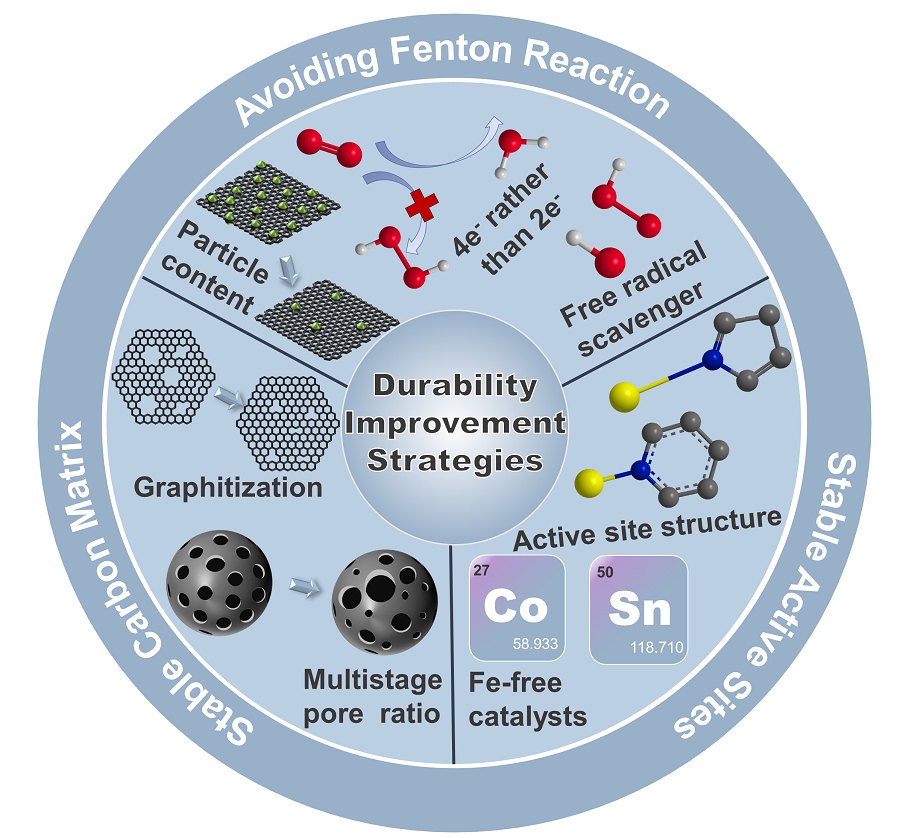
5 Durability improvement strategies of Fe-N-C catalysts
5.1 Stable carbon matrix
5.2 Stable active sites
5.3 Avoiding fenton reaction
6 Conclusion and outlook
Longhao Li , Wei Zhou , Liang Xie , Chaowei Yang , Xiaoxiao Meng , Jihui Gao . Degradation Mechanisms and Durability Improvement Strategies of Fe-N-C Catalysts for Oxygen Reduction Reaction[J]. Progress in Chemistry, 2024 , 36(3) : 376 -392 . DOI: 10.7536/PC230725
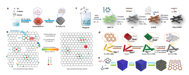
图1 Fe-N-C催化剂的合成方法:(a)一步热解法合成O-FeN4C-O示意图[30];(b)提高热解Fe-N-C催化剂的ORR稳定性的高温下微观结构演变示意图[31];(c)在不同的温度和气氛下通过三步热解法合成多孔FeN4-O-NCR催化剂示意图[34];(d)以一维Fe2O3为模板合成多孔碳纳米棒Fe/N-CNR催化剂示意图[39];(e)合成Fe-N-C/N-OMC催化剂的示意图[40]Fig. 1 Synthesis methods of Fe-N-C catalysts(a)Schematic diagram of synthesis process of O-FeN4C-O[30]. Copyright 2022 Elsevier Inc.(b)Schematic illustration of microstructure evolution at high temperatures for improving ORR stability of pyrolyzed Fe-N-C catalysts[31]. Copyright 2022 Wiley-VCH.(c)Synthesis of porous FeN4-O-NCR catalysts by three-step pyrolysis under different temperatures and atmospheres[34]. Copyright 2022 Wiley-VCH Gmbh.(d)Synthesis of porous carbon nanorod Fe/N-CNR catalysts using one-dimensional Fe2O3 as a template[39]. Copyright 2020 Elsevier B.V.(e)Schematic illustration for the synthesis of Fe-N-C/N-OMC catalyst[40]. Copyright 2020 Wiley-VCH Gmbh. |
表1 近年代表性Fe-N-C催化剂半电池和全电池测试性能Table 1 Summary of representative Fe-N-C catalysts half-cell and full-cell performance in recent years |
| Catalysts | Half-cell test | Performance | Single-cell test | Performance |
|---|---|---|---|---|
| FeNC-1200[31] | 10 000 square cycles between 0.6 and 1.0 V/RHE in O2-saturated 0.1 M HClO4 | ∆E1/2 8 mV | constant voltage of 0.5 V under H2-O2 condition for 30 h | current density loss 20% |
| Fe-AC-CVD[32] | 10 000 square cycles between 0.6 and 1.0 V/RHE in O2-saturated 0.5 M H2SO4 | ∆E1/2 17 mV | 30,000 square cycles between 0.6 and OCV in H2-Air PEMFC | current density loss 13% |
| O-FeN4-O[30] | 10 000 square cycles between 0.6 and 1.0 V/RHE in O2-saturated 0.5 M H2SO4 | ∆E1/2 10 mV | constant current density of 0.5 A·cm-2 under H2-O2 condition for 50 h | potential loss 33% |
| Fe-N-C/Pd[41] | 30 000 square cycles between 0.6 and 1.0 V/RHE in O2-saturated 0.1 M HClO4 | ∆E1/2 13.5 mV | - | - |
| ZIF-NC-0.5Fe-700[42] | 30 000 square cycles between 0.6 and 1.0 V/RHE in O2-saturated 0.5 M H2SO4 | ∆E1/2 31 mV | - | - |
| Fe-N-C/F[43] | - | - | constant voltage of 0.6 V under H2-O2 condition for 100 h | current density loss 3% |
| Fe/PI-1000-III-NH3[44] | - | - | constant current of 30mA under H2-O2 condition for 1000 h | potential loss 15% |
| PANI-FeCo-C[45] | - | - | constant voltage of 0.4 V under H2-O2 condition for 700 h | current density loss 3% |
| Fe-ZIF/CNT/1[46] | 1 000 square cycles between 0.9 and 1.4 V/RHE in N2-saturated 0.1 M HClO4 | ∆E1/2 42 mV | constant voltage of 0.4 V under H2-O2 condition for 30 h | current density loss 34% |
| Fe/N,S-HC[47] | 1 000 square cycles between 0.6 and 1.0 V/RHE in N2-saturated 0.1 M KOH | ∆E1/2 7 mV | - | - |
| Fe@MNC-OAc[35] | 10 000 square cycles between 0.6 and 1.0 V/RHE in O2-saturated 0.1 M HClO4 | ∆E1/2 9 mV | - | - |
| FeSA/FeAC-2DNPC[48] | 10 000 square cycles between 0.6 and 1.0 V/RHE in O2-saturated 0.5 M H2SO4 | ∆E1/2 15 mV | constant voltage of 0.5 V under H2-Air condition for 30 h | slight decrease in current density for the first 32 hours, then stabilized |
| P(AA-MA)(5-1)-Fe-N[49] | 5 000 square cycles between 0.6 and 1.0 V/RHE in O2-saturated 0.5 M H2SO4 | ∆E1/2 5 mV | constant voltage of 0.55 V under H2-O2 condition for 30 h | virtually no loss of current density during the initial 37 hours |
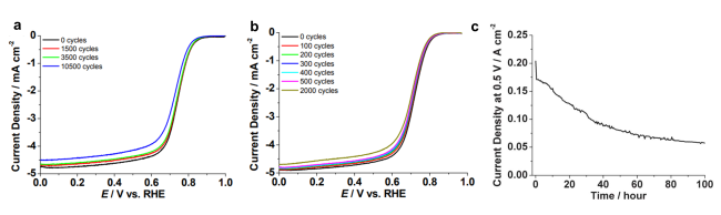
图2 在RRDE和MEA稳定性测试中测量的FeIM/ZIF-8的ORR极化曲线:RRDE测试条件包括在(a)0.1 M Ar饱和的HClO4或(b) 0.1 M O2饱和的HClO4中以50 mV·s-1的速度从0.0到1.1V循环多次,然后在O2饱和的HClO4中以10 mV·s-1的扫描速率测量极化曲线; (c)在H2-Air中进行100 h稳定性测试,测量以FeIM/ZIF-8为阴极催化剂的单体电池(Nafion 117膜)在0.5 V时的电流密度[55]Fig. 2 ORR polarization curves of FeIM/ZIF-8 measured during RRDE and MEA stability test: RRDE test conditions include cycling from 0.0 to 1.1 V at 50 mV·s-1 in(a)0.1 M Ar-purged HClO4 or(b)0.1 M O2-purged HClO4 at 25 ℃ for multiple cycles, followed by polarization curve measurement in O2-purged HClO4 at the scan rate of 10 mV·s-1.(c) 100-hour stability test by measuring the current density at 0.5 V of a single cell with FeIM/ZIF-8 as the cathode catalyst(Nafion 117 membrane)operated with H2-air[55]. Copyright 2012 The Royal Society of Chemistry. |
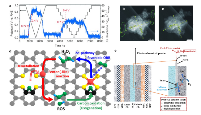
图4 (a)计时电流法实验中SFC/ICP-MS记录的铁的溶解情况,实验温度和步长分别为20 ℃和0.1 V[61]; 在0.1M HClO4中进行5000次电压循环(1.2~1.5V)前(b)后(c)拍摄的单个Fe-N-C颗粒暗场IL-STEM显微照片[61];(d)描述Fe-N-C催化剂失活机制相互耦合循环的示意图,包括脱金属、Fenton反应和碳氧化[67];(e)电化学探针法检测工况条件下催化层H2O2浓度的示意图[64]Fig. 4 Deactivation mechanism of Fe-N-C catalysts:(a)Online SFC/ICP-MS results. The Fe dissolution was recorded at 20 ℃ during a stepwise chronoamperometry experiment with a 0.1 V step size[61]; Morphology change of a single Fe-N-C particle. Dark-field IL-STEM micrographs b)before and c) after 5000 cycles performed between 1.2 and 1.5 V at 50 ℃ in a 0.1 M HClO4 electrolyte[61]. Copyright 2015 WILEY-VCH Verlag GmbH & Co.KGaA, Weinheim.(d) Schematic illustration describing autocatalytic degradation cycle comprising demetalation, Fenton(-like) reaction, and carbon oxidation[67]. Copyright 2021 Elsevier Inc.(e)Schematic of the electrochemical probe method to in-operando monitor the H2O2 concentration in the fuel cell catalyst layer[64]. Copyright 2022 Elsevier B.V. |
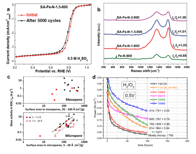
图5 构建稳定碳载体的策略:(a)SA-Fe-N-1.5-800的AST测试结果[74];(b)使用不同浓度的SA合成的SA-Fe-N催化剂与不含SA的Fe-N-C催化剂的拉曼光谱结果[74];(c)微孔/介孔面积与ORR质量活性关系[76];(d)六种含不同微孔率的Fe-N-C催化剂的稳定性测试结果[77]Fig. 5 Strategies for building stable carbon substrate:(a)AST test results of SA-Fe-N-1.5-800[74];(b)Raman spectra of SA-Fe-N catalysts synthesized using different concentrations of SA versus Fe-N-C catalysts without SA[74]. Copyright 2018 WILEY-VCH Verlag GmbH & Co.KGaA, Weinheim.(c)Relationship between mesopore and micropore area and ORR mass activity[76]. Copyright 2021 Elsevier Inc.(d)Stability test results of six Fe-N-C catalysts with different micropore ratios[77]. Copyright 2016 American Chemistry Society |
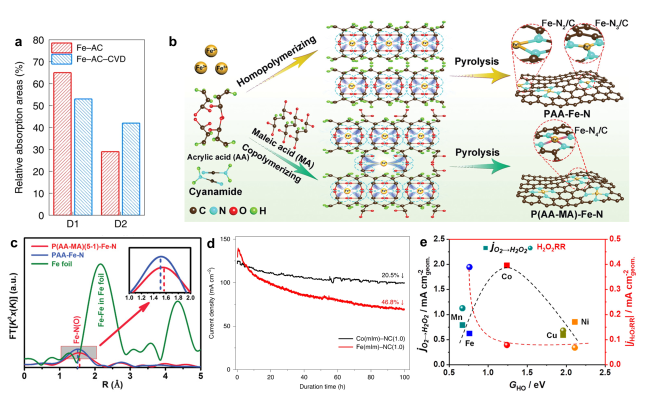
图6 构建稳定活性位点的策略:(a)CVD处理前后Fe-N-C催化剂中D1和D2位点含量的比较[32];(b)PAA-Fe-N和P(AA-MA)-Fe-N催化剂合成示意图,分别由低结合常数的PAA-Fe和高结合常数的P(AA-MA)-Fe作为前驱体制备[49];(c)P(AA-MA)(5-1)-Fe-N、PAA-Fe-N和铁箔样品的k3加权FT-EXAFS光谱[49];(d)Co(mIm)-NC(1.0)和Fe(mIm)-NC(1.0)催化剂在MEA中以0.7 V的恒定电压持续100 h的耐久性测试结果[82];(e)原子分散的M-N-C催化剂(M=Mn、Fe、Co、Ni和Cu)的电化学合成H2O2和H2O2还原趋势[83]Fig. 6 Strategies for constructing stable active sites:(a)Comparison of D1 and D2 sites contents in Fe-N-C catalysts before and after CVD treatment[32]. Copyright 2022 Springer Nature Limited.(b)PAA-Fe-N and P(AA-MA)-Fe-N catalysts were prepared by lower binding constant PAA-Fe and higher binding constant P(AA-MA)-Fe as precursor, respectively[49];(c)k3-weighted FT-EXAFS spectra of P(AA-MA)(5-1)-Fe-N, PAA-Fe-N, and Fe foil samples[49]. Copyright 2021 Wiley-VCH Gmbh.(d)Durability tests of the Co(mIm)-NC(1.0)and Fe(mIm)-NC(1.0)catalysts in MEA in 1 bar H2-air at a constant cell voltage of 0.7 V for 100 h[82]. Copyright 2020 Springer Nature.(e)The trends in electrochemical H2O2 production and H2O2 reduction over a series of M-N-C materials(M=Mn, Fe, Co, Ni, and Cu)exclusively comprising atomically dispersed M-Nx sites from molecular first-principles to bench-scale electrolyzers operating at industrial current density[83]. Copyright 2019 American Chemistry Society. |
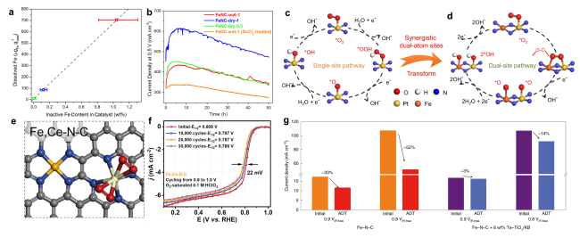
图7 避免发生芬顿反应的策略:(a)20圈快速循环稳定性测试结果:铁的溶解量与催化剂中结晶铁含量之间呈现正相关[87];(b)在0.5 V下进行50 h的恒电压耐久性测试时,电流密度与时间的关系曲线[87];Pt AMS(c)和Pt = N2 = Fe ABA(d)的ORR机制示意图[88];(e)Fe,Ce-N-C的结构示意图[92];(f)在O2饱和的0.1 M HClO4中进行30 000次电压循环(0.6~1.0V)的实验结果[92];(g)经过加速耐久性测试后,是否加入自由基清除剂Ta-TiOx/KB的PEMFC的电流密度衰减情况比较[93]Fig. 7 Strategies to avoid Fenton reaction:(a)Positive correlation between the cumulative amounts of Fe dissolved during the 20 fast cycles and the total content of crystalline Fe structures in the catalysts[87];(b)Current density versus time during the durability test for 50 h at 0.5 V[87]. Copyright 2016 American Chemistry Society. Schematic of the ORR mechanism for Pt AMS(c)and Pt = N2 = Fe ABA(d)[88]. Copyright 2022 Springer Nature.(e)The optimized structure of Fe,Ce-N-C[92];(f)accelerated degradation test(ADT)by cycling the potential(0.6~1.0 V)in O2-saturated 0.1 M HClO4 for 30 000 cycles to study the stability of the best-performing Fe,Ce-N-C[92]. Copyright 2023 Elsevier Inc.(g) Current density decay comparison for cells with and without Ta-TiOx/KB after the ADT[92]. Copyright 2022 Springer Nature Limited. |
| [1] |
|
| [2] |
|
| [3] |
|
| [4] |
|
| [5] |
|
| [6] |
|
| [7] |
|
| [8] |
|
| [9] |
|
| [10] |
|
| [11] |
|
| [12] |
|
| [13] |
|
| [14] |
|
| [15] |
|
| [16] |
(孟鹏飞, 张笑容, 廖世军, 邓怡杰. 化学进展 2022, 34(10): 2190.).
|
| [17] |
|
| [18] |
|
| [19] |
|
| [20] |
|
| [21] |
|
| [22] |
|
| [23] |
|
| [24] |
|
| [25] |
|
| [26] |
|
| [27] |
|
| [28] |
|
| [29] |
(杨孟蕊, 谢雨欣, 朱敦如. 化学进展, 2023, 35(5): 683.).
|
| [30] |
|
| [31] |
|
| [32] |
|
| [33] |
|
| [34] |
|
| [35] |
|
| [36] |
|
| [37] |
|
| [38] |
|
| [39] |
|
| [40] |
|
| [41] |
|
| [42] |
|
| [43] |
|
| [44] |
|
| [45] |
|
| [46] |
|
| [47] |
|
| [48] |
|
| [49] |
|
| [50] |
|
| [51] |
|
| [52] |
|
| [53] |
|
| [54] |
|
| [55] |
FCCT. US DOE. 2013. https://www.energy.gov/sites/prod/files/2015/08/f25/fcto_dwg_usdrive_fctt_accelerated_stress_tests_jan2013.pdf.
|
| [56] |
|
| [57] |
|
| [58] |
|
| [59] |
|
| [60] |
|
| [61] |
|
| [62] |
|
| [63] |
|
| [64] |
|
| [65] |
|
| [66] |
|
| [67] |
|
| [68] |
|
| [69] |
|
| [70] |
|
| [71] |
|
| [72] |
|
| [73] |
|
| [74] |
|
| [75] |
|
| [76] |
|
| [77] |
|
| [78] |
|
| [79] |
|
| [80] |
|
| [81] |
|
| [82] |
|
| [83] |
|
| [84] |
|
| [85] |
|
| [86] |
|
| [87] |
|
| [88] |
|
| [89] |
|
| [90] |
|
| [91] |
|
| [92] |
|
| [93] |
|
/
| 〈 |
|
〉 |