
Covalent Organic Frameworks as Cathode Materials for Metal Ion Batteries
Received date: 2023-07-20
Revised date: 2023-10-08
Online published: 2024-02-26
Supported by
National Natural Science Foundation of China(21965027)
Central Guidance on Local Science and Technology Development Fund of Ningxia Province(2023FRD05031)
National First-rate Discipline Construction Project of Ningxia: Chemical Engineering and Technology(NXY-LXK2017A04)
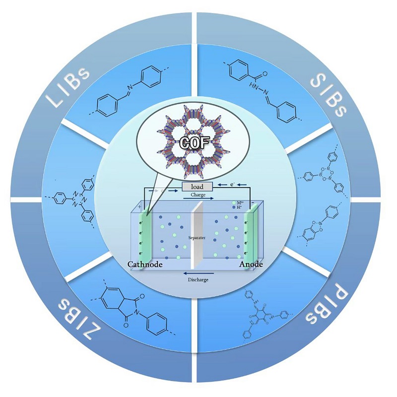
Covalent organic frameworks (COFs) are porous organic materials with periodic two-dimensional or three-dimensional network structures consisting of two or more organic molecules connected by covalent bonds. COFs have attracted considerable interest in energy storage due to their beneficial properties, including low skeletal density, high surface area, high porosity, structural designability and functional modifiability. COFs offer unique advantages as positive electrode materials for metal ion batteries due to their rich redox active sites and open framework structure. However, their application in energy storage is limited by challenges such as poor conductivity, low energy density, limited number of available active sites, and blockage of ion transport channels. This article provides a comprehensive review of recent research on COFs as positive electrode materials for metal ion batteries, discussing their types, design strategies, and synthesis methods. Additionally, it presents an overview of the electrochemical energy storage mechanisms from the perspective of different active groups, and the applications of COFs in various metal ion batteries. Finally, it highlights the prospects and challenges of using COFs in energy storage.
1 Introduction
2 Types of COFs
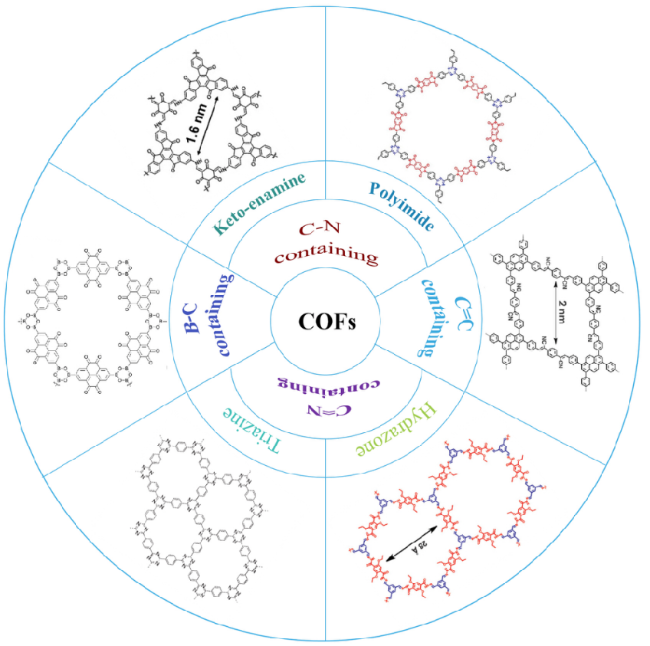
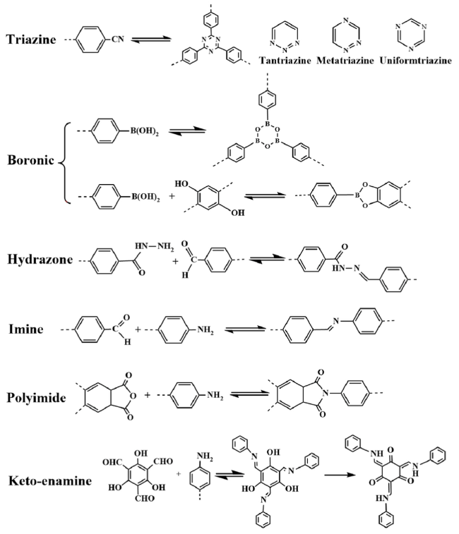
2.1 B-C containing
2.2 C-N containing
2.3 C=N containing
2.4 C=C containing
3 Synthesis method of COFs
3.1 Solvothermal synthesis
3.2 Ionic thermal synthesis
3.3 Microwave-assisted synthesis
3.4 Mechanochemical synthesis
3.5 Sonochemical synthesis
4 Microstructure design strategy for COFs
4.1 Introduction of redox active sites
4.2 Crystallinity adjustment
4.3 Interlayer stripping strategy
5 Application of COFs in different metal ion batteries
5.1 Lithium-ion batteries
5.2 Sodium-ion batteries
5.3 Potassium-ion batteries
5.4 Aqueous zinc batteries
6 Conclusion and prospect
Wenbo Zhou , Xiaoman Li , Min Luo . Covalent Organic Frameworks as Cathode Materials for Metal Ion Batteries[J]. Progress in Chemistry, 2024 , 36(3) : 430 -447 . DOI: 10.7536/PC230720
表1 具有代表性的电极材料在金属离子电池中的性能比较Table 1 Performance comparison of representative electrode materials in metal ion batteries |
| Cathode material | Application Scenarios | Specific surface area (m2·g-1) | Discharge specific capacity (mAh·g-1) | Cycle life (capacity retention/cycle/rate)(A·g-1) | ref |
|---|---|---|---|---|---|
| MnO2 | LIBs | 43.601 | 148/0.05 A·g-1 | 44%/100/0.1 | 12 |
| α-MnO2 | AZIBs | 70.8 | 240/0.1 A·g-1 | 58.3%/300/0.1 | 13 |
| K+/γ-MnO2 | SIBs | 148.2 | 300/0.1 A·g-1 | 60%/200/0.1 | 14 |
| Mn3O4@rGO | LIBs | 83 | 741/0.1 A·g-1 | 65.9%/300/0.5 | 15 |
| MgMn2O4 | AZIBs | — | 243/0.1 A·g-1 | 80%/500/0.5 | 16 |
| V2O5 | AZIBs | 43 | 224/0.1 A·g-1 | 75%/400/0.1 | 17 |
| NaV3O8 | RMBs | 201 | 184/0.1 A·g-1 | 88.3%/100/0.5 | 18 |
| Co/LiNi0.5Mn1.5O4 | LIBs | — | 120/1 A·g-1 | 81%/2000/5 | 19 |
| V2O3@rGO | AZIBs | 133.36 | 240/0.5 A·g-1 | 80%/1000/10 | 20 |
| NaFeⅢ[FeⅢ(CN)6] | SIBs | 189.19 | 120.3/0.01 A·g-1 | 59.1%/50/0.075 | 21 |
| Na2Fe(C2O4)SO4 | SIBs | — | 80/0.2 A·g-1 | 85%/500/5 | 22 |
| CuHCF(Fe2+) | CIBs | 100.2 | 54.5/0.02 A·g-1 | 90.43%/1000/0.02 | 23 |
| DAAQ-ECOF | LIBs | 216 | 148/0.02 A·g-1 | 74%/1800/0.5 | 24 |
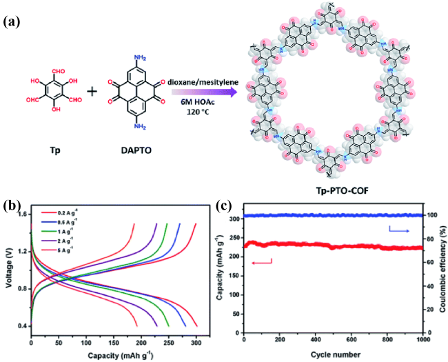
| TP-PTO-COF | AZIBs | 601 | 301.4/0.2 A·g-1 | 95%/1000/2 | 25 |
| HATN-AQ-COF | LIBs | 725 | 319/0.179 A·g-1 | 80%/3000/ 3.58 | 26 |
| TPDA-PMDA-COF | LIBs | 2669 | 233/0.5 A·g-1 | 57.1%/1800/5 | 27 |
| TQBQ-COF | SIBs | 94.36 | 452/0.02 A·g-1 | 96.4%/1000/1 | 28 |
| COF-TMT-BT | AZIBs | 342.5 | 283.5/0.1 A·g-1 | 96.2%/2000/0.1 | 29 |
表2 不同方法合成COFs的性能指标Table 2 Performance indexes of COFs synthesized by different methods |
| Synthesis method | Typical material | Recation time | Recation Temperature (℃) | Specific surface area (m2·g-1) | ref |
|---|---|---|---|---|---|
| Solvothermal | COF-1 | 72 h | 120 | 711 | 32 |
| TAPB-PZI | 72 h | 150 | 598.3 | 53 | |
| TFPM-PDAN | 72 h | 100 | 728.4 | 54 | |
| Ionic thermal | CTF-1 | 40 h | 400 | 791 | 71 |
| TAPB-PTCDA | 48 h | 300 | 1250 | 72 | |
| FCTF | 40 h | 400 | — | 73 | |
| Microwave | TTA-DPF | 30 min | 110 | 900 | 74 |
| LZU-1 | 30 min | 120 | 729 | 75 | |
| AEM-COF-2 | 40 min | 120 | 1487 | 76 | |
| Mechanochemical | TpPa-1 | 40 min | — | 61 | 67 |
| TpBpy-MC | 1.5 h | — | 293 | 77 | |
| NUS-9 | 45 min | — | 102 | 78 | |
| Phonochemistry | COF-1 | 1-2 h | — | 719 | 79 |
| COF-1 NN | 48 h | 100 | — | 70 |
表3 COFs在不同金属离子电池正极材料中的应用Table 3 COFs application in different metal ion battery cathode material |
| Name of the COFs | Batteries | Voltage Window (V) | Discharge specific capacity (mAh·g-1) | Cycle life (capacity retention/cycle/rate) | ref |
|---|---|---|---|---|---|
| TPPDA-CuPor-COF USTB-6-COF@G BFPPQ-COF@CNT IISERP-COF22 COF-N TAQ-BQ-COF HAQ-COF S@TAPT-COF GOPH-COF BT-PTO-COF TP-TA-COF SCNMC-COF TFPPy-ICTO-COF HATN-HHTP@CNT HATN-HHTP@CNT BAV-COF-Br- HATN-AQ-COF TPF-1S-COF DAPO-TpOMe-COF TPDA-PMDA-COF HTAQ-COF PT-COF50 E-TP-COF TPPDA-PI-COF NTCDI-COF PICOF-1 F-COF TP-COF/CNTs QPP-FAC-Pc-COF COF-CRO Tp-DANT-COF PI-ECOFs/rGO PD-NDI-Lp PPTODB-COF PIBN-G TpBpy-COF | LIBs LIBs LIBs AZIBs MIBs AZIBs AZIBs SIBs AZIBs AZIBs LIBs LIBs LIBs LIBs KIBs SIBs LIBs LIBs LIBs LIBs AZIBs LIBs LIBs LIBs LIBs SIBs KIBs KIBs KIBs LIBs LIBs LIBs LIBs LIBs LIBs AIBs | 1.5~4.2 1.2~3.9 1.7~3.3 0.2~1.6 0.3~2.5 0.4~1.6 0.26~1.5 1.5~3.2 0.2~1.6 0.4~1.5 1.2~4.3 3.6~4.2 0.05~3.0 1.2~3.8 1.2~3.8 1.4~3.9 1.2~3.9 0.01~3 1.5~4.2 1.2~4.3 0.1~1.45 1.5~3.5 1.5~3.5 2.6~4.1 1.5~3.5 0.01~3 0.01~3 0.01~3 0.01~3 0.5~4.5 1.5~4.0 1.5~3.5 1.5~3.5 1.5~3.5 1.5~3.5 0.01~2.3 | 142/0.06 A·g-1 285/0.2 C 87.5/0.2 C 690/1.5 A·g-1 120/0.05 A·g-1 208/0.1 A·g-1 339/0.1 A·g-1 109/0.1 A·g-1 70.2/0.015 A·g-1 225/0.1 A·g-1 207/0.2 A·g-1 160.5/1 C 338/0.1 A·g-1 231/0.05 A·g-1 218/0.1 A·g-1 152/0.05 A·g-1 319/0.5 C 1563/0.08 C 81.9/0.1 A·g-1 233/0.5 A·g-1 305/0.04 A·g-1 280/0.2 A·g-1 110/0.2 A·g-1 47/0.2 A·g-1 212/0.1 A·g-1 237/0.1 C 248/0.05 A·g-1 290/0.1 A·g-1 424/0.05 A·g-1 268/0.1 C 144.4/0.34 C 124/0.1 C 77/0.5 C 198/0.02 A·g-1 271/0.1 C 307/0.1 A·g-1 | 85%/3000/1 A·g-1 70%/6000/5 C 86%/600/5 C 83%/6000/5 A·g-1 99%/300/0.2 A·g-1 87%/1000/1 A·g-1 99%/10000/5 A·g-1 76%/2000/2 A·g-1 82%/500/0.015 A·g-1 98%/10000/5 A·g-1 93%/1500/5A·g-1 87.5%/200/1 C 100%/1000/1 A·g-1 100%/6900/0.5 A·g-1 86.5%/2400/0.5 A·g-1 76.5%/500/0.25 A·g-1 80%/3000/10 C 43.5%/1000/2 C 94%/200/0.1 A·g-1 57.1%/1800/5 A·g-1 87%/1000/2 A·g-1 82%/3000/2 A·g-1 87.3%/500/0.2 A·g-1 65%/3000/1 A·g-1 86%/1500/2 A·g-1 84%/175/0.3 C 99.7%/5000 /1 A·g-1 80%/500/0.2 A·g-1 99.9%/10000/2 A·g-1 99%/100/0.1 C 95%/600/7.5 C 72.6%/300/1 C 80%/400/2.5 C 68.3%/150/0.02 A·g-1 86%/300/5 C 100%/13000/2 A·g-1 | 98 99 100 101 102 88 103 104 105 82 106 107 108 109 109 110 26 111 112 27 113 114 115 116 117 118 119 120 121 122 123 124 125 126 127 128 |
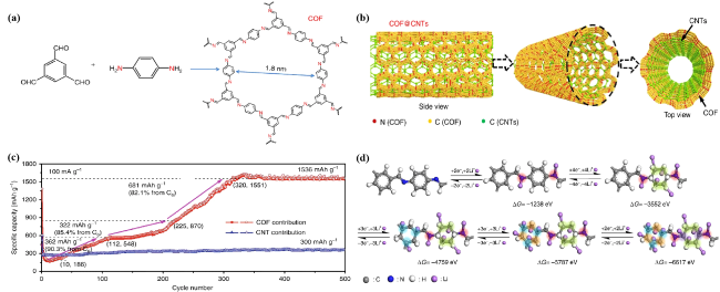
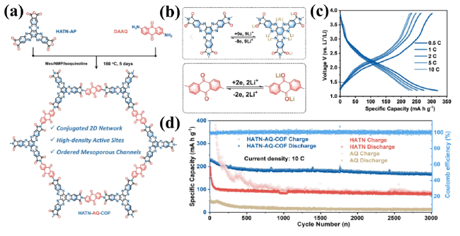
图16 (a) HATN-AQ-COF的合成示意图;(b) HATN-AQ-COF的电化学氧化还原机理;(c) 不同电流密度下的充放电曲线;(d) HATN-AQ-COF的长期循环性能[26]Fig. 16 (a) Schematic diagram of HATN-AQ-COF synthesis; (b) the electrochemical redox mechanism of HATN-AQ-COF; (c) charge/discharge profiles for varied current densities; (d) long-term cycling performance of HATN-AQ-COF[26] |
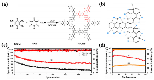
图17 (a) TH-COF的合成示意图;(b) TH-COF的电化学氧化还原机理;(c) TH-COF的长期循环性能;(d) TH-COF在5 C和20 C电流密度下的循环性能[132]Fig. 17 (a) Schematic diagram of HATN-AQ-COF synthesis; (b) the electrochemical redox mechanism of HATN-AQ-COF; (c) long-term cycling performance of TH-COF; (d) long-term cycling performance of TH-COF at 5 C and 20 C [132] |
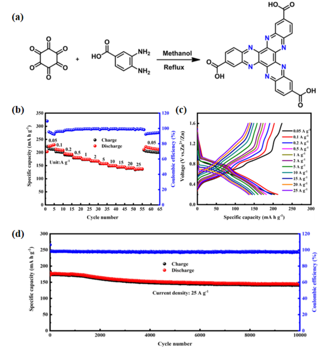
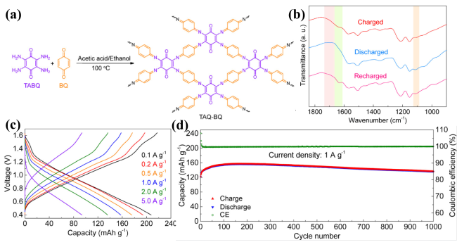
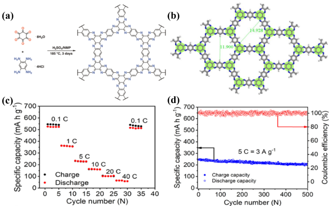
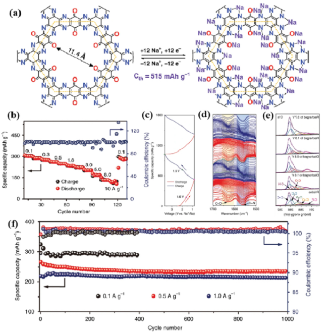
图19 (a) TQBQ-COF的化学结构和可能的电化学氧化还原机理;(b) TQBQ-COF在0.02 A·g-1下的充放电曲线;(c) TQBQ-COF的原位FTIR光谱;(d) TQBQ-COF在不同充/放电状态下的C 1s XPS谱;(e) TQBQ-COF的倍率性能;(f) TQBQ-COF的长期循环性能[28]Fig. 19 (a) The chemical structure and possible electrochemical redox mechanism of TQBQ-COF; (b) Discharge/charge profiles of TQBQ-COF electrode at 0.02 A·g-1; (c) In-situ FTIR spectra of TQBQ-COF; (d) the C1s XPS spectra of TQBQ-COF electrodes at different charge/discharge states; (e) rate performance of TQBQ-COF; (f) long-term cycling performance of TQBQ-COF [28] |
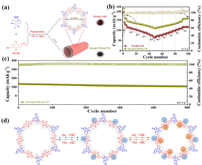
图20 (a) DAAQ-COF和DAAQ-COF@CNT合成示意图;(b) DAAQ-COF和DAAQ-COF@CNT的倍率性能;(c) DAAQ- COF@CNT的长期循环性能;(d) DAAQ- COF@CNT的电化学氧化还原机理[140]Fig. 20 (a) Schematic illustration of synthesis of the DAAQ-COF and DAAQ-COF@CNT; (b) rate performances of the DAAQ-COF and DAAQ-COF@CNT; (c) long-term cycling performance of DAAQ-COF@CNT; (d) electrochemical redox mechanism of DAAQ-COF@CNT in charge and discharge process [140] |
| [1] |
|
| [2] |
|
| [3] |
|
| [4] |
|
| [5] |
|
| [6] |
|
| [7] |
|
| [8] |
|
| [9] |
|
| [10] |
|
| [11] |
|
| [12] |
|
| [13] |
|
| [14] |
|
| [15] |
|
| [16] |
|
| [17] |
|
| [18] |
|
| [19] |
|
| [20] |
|
| [21] |
|
| [22] |
|
| [23] |
|
| [24] |
|
| [25] |
|
| [26] |
|
| [27] |
|
| [28] |
|
| [29] |
|
| [30] |
|
| [31] |
|
| [32] |
|
| [33] |
|
| [34] |
|
| [35] |
|
| [36] |
|
| [37] |
|
| [38] |
|
| [39] |
|
| [40] |
|
| [41] |
|
| [42] |
|
| [43] |
|
| [44] |
|
| [45] |
|
| [46] |
|
| [47] |
|
| [48] |
|
| [49] |
|
| [50] |
|
| [51] |
|
| [52] |
|
| [53] |
|
| [54] |
(吕以仙. 有机化学第七版. 北京: 人民卫生出版社, 2008, 06.)
|
| [55] |
|
| [56] |
|
| [57] |
|
| [58] |
|
| [59] |
|
| [60] |
|
| [61] |
|
| [62] |
|
| [63] |
|
| [64] |
|
| [65] |
|
| [66] |
|
| [67] |
|
| [68] |
|
| [69] |
|
| [70] |
|
| [71] |
|
| [72] |
|
| [73] |
|
| [74] |
|
| [75] |
|
| [76] |
|
| [77] |
|
| [78] |
|
| [79] |
|
| [80] |
|
| [81] |
|
| [82] |
|
| [83] |
|
| [84] |
|
| [85] |
|
| [86] |
|
| [87] |
|
| [88] |
|
| [89] |
|
| [90] |
|
| [91] |
|
| [92] |
|
| [93] |
|
| [94] |
|
| [95] |
|
| [96] |
|
| [97] |
|
| [98] |
|
| [99] |
|
| [100] |
|
| [101] |
|
| [102] |
|
| [103] |
|
| [104] |
|
| [105] |
|
| [106] |
|
| [107] |
|
| [108] |
|
| [109] |
|
| [110] |
|
| [111] |
|
| [112] |
|
| [113] |
|
| [114] |
|
| [115] |
|
| [116] |
|
| [117] |
|
| [118] |
|
| [119] |
|
| [120] |
|
| [121] |
|
| [122] |
|
| [123] |
|
| [124] |
|
| [125] |
|
| [126] |
|
| [127] |
|
| [128] |
|
| [129] |
|
| [130] |
|
| [131] |
|
| [132] |
|
| [133] |
|
| [134] |
|
| [135] |
|
| [136] |
|
| [137] |
|
| [138] |
|
| [139] |
|
| [140] |
|
| [141] |
|
| [142] |
|
| [143] |
|
| [144] |
|
| [145] |
|
| [146] |
|
| [147] |
|
| [148] |
|
| [149] |
|
| [150] |
|
| [151] |
|
/
| 〈 |
|
〉 |