
Modified Nafion Membrane in Vanadium Redox Flow Battery
Received date: 2023-03-22
Revised date: 2023-08-02
Online published: 2023-09-10
Supported by
National Natural Science Foundation of China(51774302)
National Natural Science Foundation of China(52074320)
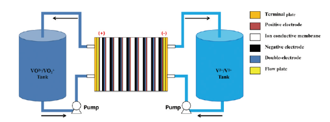
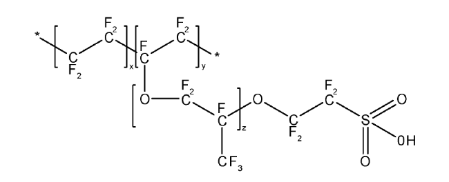
Vanadium redox flow battery (VRB) is the most promising large-scale energy storage system due to its flexibility, high efficiency and being pollution-free, which has attracted wide attention from researchers. The separator is a key component of VRB, which plays a role in isolating vanadium ions from cross-penetration and providing proton transmembrane transfer channels. Nafion membranes produced by DuPont are the most commonly used ion exchange membranes for VRB due to their good chemical stability and high proton conductivity. However, they have problems such as poor vanadium resistance and high cost. Therefore, the key point of current research is to control the ion exchange capacity of the Nafion membrane reasonably, improve the vanadium resistance capacity of the Nafion membrane while retaining the excellent performance of the Nafion membrane through modification methods, and reduce the cost of the Nafion membrane. In this paper, the working principle of VRB and the performance characteristics of Nafion membrane are discussed. The current trend and future direction of Nafion membrane modification methods are also discussed in detail. This is of great significance for understanding the structure-activity relationship between modified Nafion membrane structure and battery performance, and guiding the future modification and design of Nafion membrane.
1 Introduction
2 Principle of VRB
3 Performance evaluation of VRB
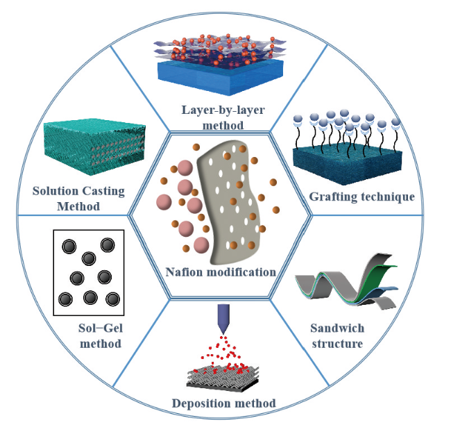
4 Functional modification method of Nafion membrane
4.1 In situ sol-gel method
4.2 Functional material blending
4.3 Spin-coating method
4.4 Deposition method
4.5 Polymer grafting
4.6 Construction of sandwich structure
5 Conclusion and prospect

Key words: vanadium redox flow battery (VRB); Nafion; ion exchange; proton conduction
Yang Haoling , Xu Kunyu , Zhang Qi , Tao Liang , Yang Zihao , Dong Zhaoxia . Modified Nafion Membrane in Vanadium Redox Flow Battery[J]. Progress in Chemistry, 2023 , 35(11) : 1595 -1612 . DOI: 10.7536/PC230323
表1 膜的重要性能以及钒电池充放电测试评估方法Table 1 The important performance of the membrane and the evaluation method of charge and discharge test of vanadium battery |
| Properties | method | equation | ref | |
|---|---|---|---|---|
| Cell performance | Coulombic efficiency (CE) | Charge discharge test | 23 | |
| Voltage efficiency (VE) | ||||
| Energy efficiency (EE) | ||||
| Membrane properties | Ion exchange capacity (IEC) | back-titration method | 24,25 | |
| Water uptake (WU) | — | 26 | ||
| Swelling ratio (SR) | — | 26 | ||
| Water transport | water transport experiment. | — | 27 | |
| Proton conductivity (R) | — | 28 | ||
| Permeabilit(σ) | — | 29 | ||
| Permeability(P0) | UV-Visible spectroscopy | 30,31 | ||
| Ion selectivity(S) | — | 32 | ||
| Chemical stability | — | 33 |
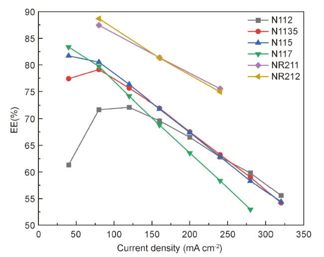
表2 目前商业常用Nafion膜性能汇总Table 2 Performance summary of Nafion membranes commonly used in commercial applications |
| membrane | Casting procedure | Water uptake (WU) | Swelling ratio(SR) | Thickness (μm) | IEC(mmol/g) | Conductivity (mS/cm) | ref |
|---|---|---|---|---|---|---|---|
| N115 | Extruded | 32.1±2.2 | 69.0±1.5 | 127 | 0.87±0.02 | 100 | 34,36,37 |
| N117 | 34.1±1.1 | 63.0±3.0 | 183 | 0.88±0.01 | 96 | 34,36,38,39 | |
| N112 | 44.1±1.8 | 73.9±1.6 | 50 | 0.84±0.02 | 102 | 34,36 | |
| N1135 | 32.5±2.0 | 67.6±1.4 | 88 | 0.86±0.01 | 98 | 34,36 | |
| NR211 | Dispersion cast | 40 | — | 25 | — | — | 37 |
| NR212 | 47 | — | 50 | 0.88 | 70 | 37⇓~39 |
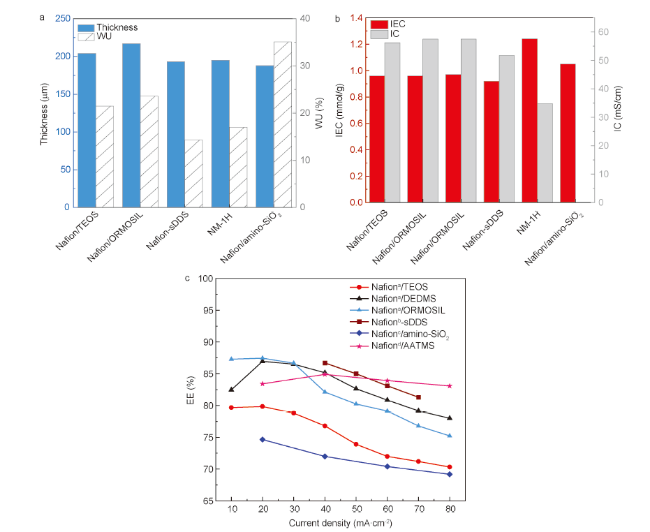
图5 (a)原位溶胶-凝胶法改性后Nafion膜的厚度及吸水率,(b) 原位溶胶-凝胶法改性后Nafion膜的离子交换能力及质子电导率,(c) 原位溶胶-凝胶法改性后Nafion膜在不同电流密度下的能量效率[43~51]Fig.5 (a) The thickness and water absorption of Nafion membrane modified by in-situ-gel method, (b) The ion exchange capacity and proton conductivity of Nafion membrane modified by in-situ-gel method, (c) The energy efficiency of Nafion membrane modified by in-situ-gel method at different current densities[43~51] |
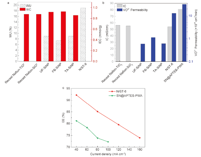
图6 (a) SiO2溶液浇铸法改性后Nafion膜的厚度及吸水率,(b) SiO2溶液浇铸法改性后Nafion膜的质子电导率及钒离子渗透率,(c) SiO2溶液浇铸法改性后Nafion膜在不同电流密度下的能量效率[52~56]Fig.6 (a) The thickness and water absorption of Nafion membrane modified by SiO2 solution casting, (b) The proton conductivity and vanadium ion permeability of Nafion membrane modified by SiO2 solution casting, (c) The energy efficiency of Nafion membrane modified by SiO2 solution casting at different current densities[52~56] |
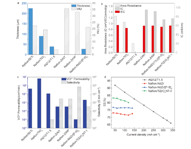
图7 (a) TiO2以及氧化锆溶液浇铸法改性后Nafion膜的厚度及吸水率,(b) TiO2以及氧化锆溶液浇铸法改性后Nafion膜的区域电阻、质子电导率及离子交换能力,(c) TiO2以及氧化锆溶液浇铸法改性后Nafion膜的钒离子渗透率及离子选择性,(d) TiO2以及氧化锆溶液浇铸法改性后Nafion膜在不同电流密度下的能量效率[59~64]Fig.7 ( a ) The thickness and water absorption of Nafion membranes modified by TiO2 and zirconia solution casting, ( b ) The area resistance, proton conductivity and ion exchange capacity of Nafion membranes modified by TiO2 and zirconia solution casting, ( c ) The vanadium ion permeability and ion selectivity of Nafion membranes modified by TiO2 and zirconia solution casting, ( d ) The energy efficiency of Nafion membranes modified by TiO2 and zirconia solution casting at different current densities[59~64] |
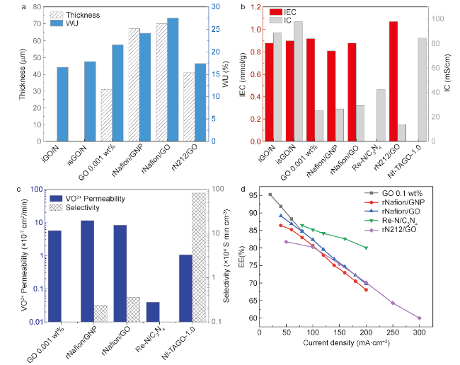
图8 (a) GO溶液浇铸法改性后Nafion膜的厚度及吸水率,(b) GO溶液浇铸法改性后Nafion膜的质子电导率及离子交换能力,(c) GO溶液浇铸法改性后Nafion膜的钒离子渗透率及离子选择性,(d) GO溶液浇铸法改性后Nafion膜在不同电流密度下的能量效率[65~71]Fig.8 (a) The thickness and water absorption of Nafion membrane modified by GO solution casting. (b) The proton conductivity and ion exchange capacity of Nafion membrane modified by GO solution casting. (c) The vanadium ion permeability and ion selectivity of Nafion membrane modified by GO solution casting. (d) The energy efficiency of Nafion membrane modified by GO solution casting at different current densities[65~71] |
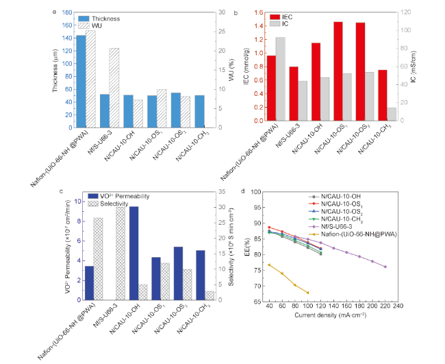
图9 (a) MOFs溶液浇铸法改性后Nafion膜的厚度及吸水率,(b) MOFs溶液浇铸法改性后Nafion膜的质子电导率及离子交换能力,(c) MOFs溶液浇铸法改性后Nafion膜的钒离子渗透率及离子选择性,(d) MOFs溶液浇铸法改性后Nafion膜在不同电流密度下的能量效率[72~74]Fig.9 (a) The thickness and water absorption of Nafion membrane modified by MOFs solution casting, (b) The proton conductivity and ion exchange capacity of Nafion membrane modified by MOFs solution casting, (c) The vanadium ion permeability and ion selectivity of Nafion membrane modified by MOFs solution casting, (d) The energy efficiency of Nafion membrane modified by MOFs solution casting at different current densities[72~74] |
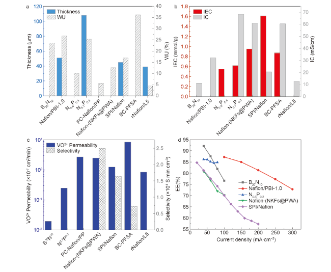
图10 (a) 聚合物溶液浇铸法改性后Nafion膜的厚度及吸水率,(b) 聚合物溶液浇铸法改性后Nafion膜的质子电导率及离子交换能力,(c) 聚合物溶液浇铸法改性后Nafion膜的钒离子渗透率及离子选择性,(d) 聚合物溶液浇铸法改性后Nafion膜在不同电流密度下的能量效率[75~88]Fig.10 (a) The thickness and water absorption of Nafion membrane modified by polymer solution casting, (b) The proton conductivity and ion exchange capacity of Nafion membrane modified by polymer solution casting, (c) The vanadium ion permeability and ion selectivity of Nafion membrane modified by polymer solution casting, (d) The energy efficiency of Nafion membrane modified by polymer solution casting at different current densities[75~88] |
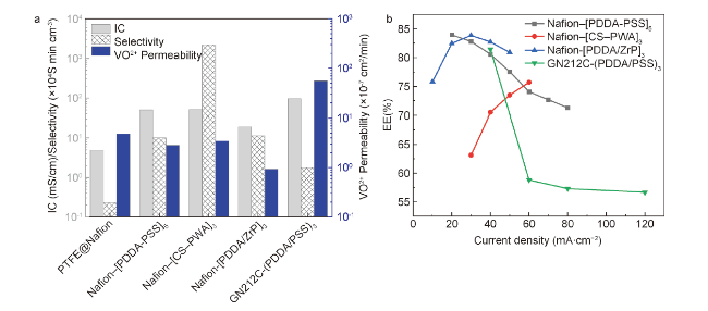
图11 (a)沉积法改性后Nafion膜的质子电导率、钒离子渗透率及离子选择性,(b) 沉积法改性后Nafion膜在不同电流密度下的能量效率[91~100]Fig.11 (a) Proton conductivity, vanadium ion permeability and ion selectivity of Nafion membrane modified by deposition method, (b) Energy efficiency of Nafion membrane modified by deposition method at different current densities[91~100] |
表3 层层自组装法制备膜研究现状汇总Table 3 Summary of research status of membrane preparation by layer-by-layer method |
| Membrane | Basis | Positive electricity | Negative electricity | layer | ref |
|---|---|---|---|---|---|
| Nafion-[PDDA-PSS]5 | Nafion117 | Poly(diallyldimethylammonium chloride) (PDDA) | Polyanion poly(sodium styrene sulfonate) (PSS) | 5 | 96 |
| Nafion-[CS-PWA]3 | Nafion212 | Polycation chitosan (CS) | PWA | 3 | 97 |
| N117-(PEI/Nafion)10 | Nafion117 | Polyethylenimine (PEI) | Nafion | 10 | 98 |
| Nafion-[PDDA/ZrP]3 | Nafion115 | PDDA | zirconium phosphate (ZrP) nanosheets | 3 | 99 |
| GN212C-[PDDA-PSS]3 | GN212C | PDDA | PSS | 3 | 100 |
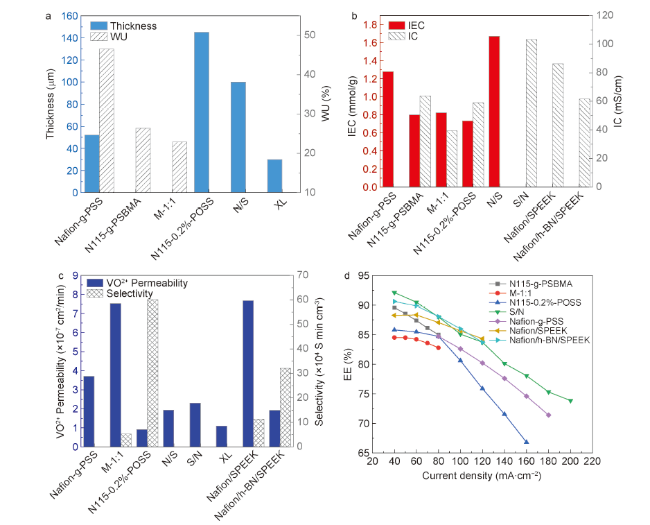
图12 (a) 聚合物接枝法以及构建夹层结构改性后的Nafion膜的厚度及吸水率,(b) 聚合物接枝法以及构建夹层结构改性后的Nafion膜的质子电导率及离子交换能力,(c) 聚合物接枝法以及构建夹层结构改性后的Nafion膜的钒离子渗透率及离子选择性,(d) 聚合物接枝法以及构建夹层结构改性后的Nafion膜在不同电流密度下的能量效率[101~112]Fig.12 (a) Thickness and water absorption of Nafion membranes modified by polymer grafting and construction of sandwich structure ; (b) Proton conductivity and ion exchange capacity of Nafion membranes modified by polymer grafting and construction of sandwich structure ; (c) Vanadium ion permeability and ion selectivity of Nafion membranes modified by polymer grafting and construction of sandwich structure ; (d) Energy efficiency of Nafion membranes modified by polymer grafting and construction of sandwich structure at different current densities[101~112] |
| [1] |
|
| [2] |
|
| [3] |
|
| [4] |
|
| [5] |
|
| [6] |
|
| [7] |
|
| [8] |
|
| [9] |
|
| [10] |
|
| [11] |
|
| [12] |
|
| [13] |
|
| [14] |
|
| [15] |
|
| [16] |
|
| [17] |
|
| [18] |
|
| [19] |
|
| [20] |
|
| [21] |
|
| [22] |
|
| [23] |
|
| [24] |
|
| [25] |
|
| [26] |
|
| [27] |
|
| [28] |
|
| [29] |
|
| [30] |
|
| [31] |
|
| [32] |
|
| [33] |
|
| [34] |
|
| [35] |
|
| [36] |
|
| [37] |
|
| [38] |
|
| [39] |
|
| [40] |
|
| [41] |
|
| [42] |
|
| [43] |
|
| [44] |
|
| [45] |
|
| [46] |
|
| [47] |
|
| [48] |
|
| [49] |
|
| [50] |
|
| [51] |
|
| [52] |
|
| [53] |
|
| [54] |
|
| [55] |
|
| [56] |
|
| [57] |
|
| [58] |
|
| [59] |
|
| [60] |
|
| [61] |
|
| [62] |
|
| [63] |
|
| [64] |
|
| [65] |
|
| [66] |
|
| [67] |
|
| [68] |
|
| [69] |
|
| [70] |
|
| [71] |
|
| [72] |
|
| [73] |
|
| [74] |
|
| [75] |
|
| [76] |
|
| [77] |
|
| [78] |
|
| [79] |
|
| [80] |
|
| [81] |
|
| [82] |
|
| [83] |
|
| [84] |
|
| [85] |
|
| [86] |
|
| [87] |
|
| [88] |
|
| [89] |
|
| [90] |
|
| [91] |
|
| [92] |
|
| [93] |
|
| [94] |
|
| [95] |
|
| [96] |
|
| [97] |
|
| [98] |
|
| [99] |
|
| [100] |
|
| [101] |
|
| [102] |
|
| [103] |
|
| [104] |
|
| [105] |
|
| [106] |
|
| [107] |
|
| [108] |
|
| [109] |
|
| [110] |
|
| [111] |
|
| [112] |
|
/
| 〈 |
|
〉 |