
Enhanced Mechanism of Supercapacitance by Regulating the Surface Interface of Transition Metal Compounds
Received date: 2023-10-30
Revised date: 2024-04-01
Online published: 2024-07-01
Supported by
National Natural Science Foundation of China(61774033)
Science and Technology Research Program of Chongqing Municipal Education Commission(KJZD-K202201206)
Science and Technology Research Program of Chongqing Municipal Education Commission(KJQN202101238)
Natural Science Foundation of Chongqing(cstc2021jcyj-msxmX1016)
Science and Technology Innovation Program of Wanzhou(wzstc20220302)
National Undergraduate Training Program of Innovation and Entrepreneurship(202310643004)
National Undergraduate Training Program of Innovation and Entrepreneurship(202310643009)
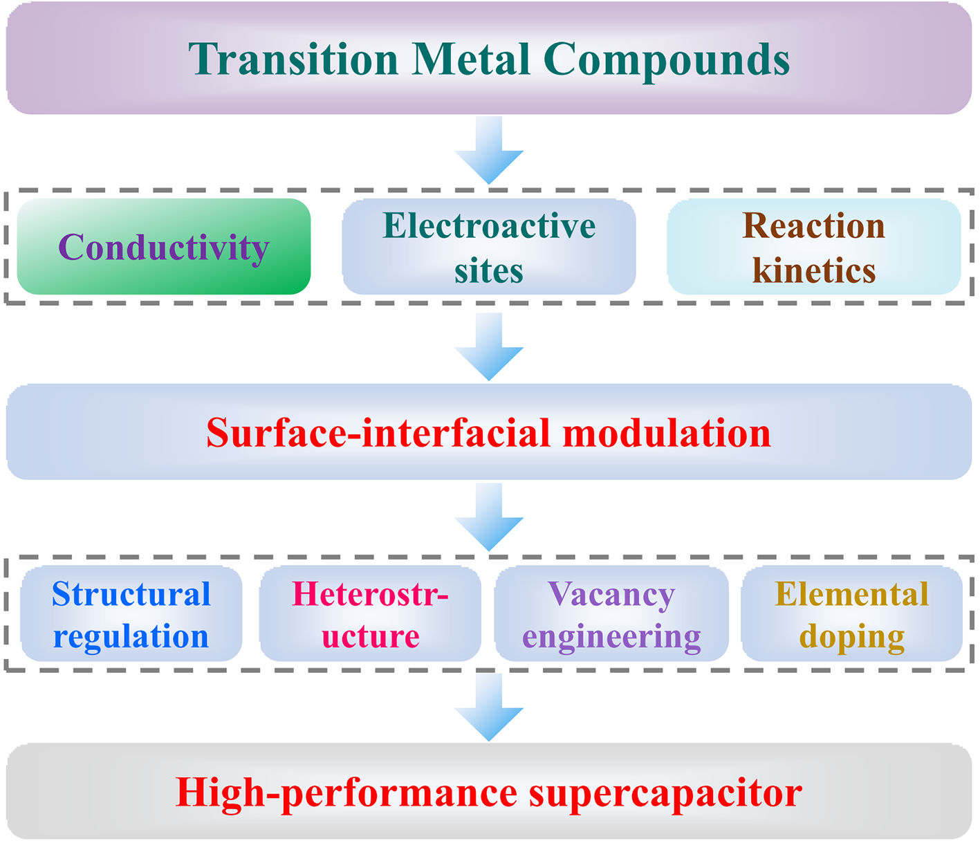
the development of supercapacitors with high efficiency and good stability is of great significance in alleviating the energy crisis and environmental pollution issues.transition metal compounds store charge through Faraday redox reactions,leading to higher specific capacities.However,transition metal compounds suffer from poor electrical conductivity,slow reaction kinetics,and few exposed electroactive sites,thus leading to a definite difficulty in practical applications.in This paper,We have summarized the research progress of surface-interface modulation strategies in enhancing the electrochemical performance of supercapacitors to address the problems of transition metal compounds,such as morphology modulation,heterojunction,elemental doping,and vacancy engineering.this paper focuses on the mechanism of the above-mentioned methods from the perspective of morphological and electronic structure modulation on the physical and chemical properties of active materials.we aim to clarify the performance enhancement mechanism of supercapacitors and provide an important theoretical basis for developing high-performance and high-stability supercapacitors.Finally,the reasons for structural design and electronic modulation to improve the performance of supercapacitors are summarized,and the challenges faced by structural design and electronic modulation in constructing high-performance supercapacitors are outlined。
1 Introduction
2 Surface-interface modulation strategies for transition metal compound electrode materials
2.1 Structural regulation
2.2 Heterostructure
2.3 Elemental doping
2.4 Vacancy engineering
3 Conclusion and outlook
Key words: surface interface; supercapacitance; electronic structure; morphology; mechanism
Xing Chen , Demin Jiang , Kun Xie , Lijun Liu , Yin Wang , Yuqiao Wang . Enhanced Mechanism of Supercapacitance by Regulating the Surface Interface of Transition Metal Compounds[J]. Progress in Chemistry, 2024 , 36(7) : 961 -974 . DOI: 10.7536/PC231016
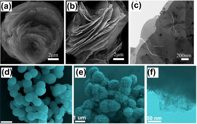
图3 多孔NiCo2O4纳米花的(a, b)SEM和(c)TEM表征图[18];Ni/Co-层状双氢氧化物微球的(d, e)SEM和(f)TEM表征图[19]Fig. 3 (a, b) SEM and (c) TEM images of porous NiCo2O4 nanoflowers[18]. Copyright 2014, Elsevier. (d, e) SEM and (f) TEM images of Ni/Co-layered double hydroxide microspheres[19]. Copyright 2019, American Chemical Society |
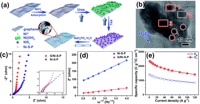
图4 G/Ni-S-P复合物:(a)制备示意图;(b)透射电镜图;(c)电化学阻抗图;(d)低频区Z′和ω−1/2关系图;(e)不同电流密度下材料的质量和体积比电容[25]Fig. 4 G/Ni-S-P composite: (a) Schematic diagram of the preparation, (b) HRTEM image, (c) Nyquist plots, (d) linear relationship between Z′ and ω−1/2 in the low-frequency region, (e) gravimetric and volumetric specific capacities at different current densities[25]. Copyright 2019, Royal Society of Chemistry |
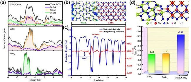
图5 (a)NiSe2、CoSe2和NiSe2/CoSe2异质结的总态密度和分波态密度;(b)NiSe2和CoSe2异质结界面差分电荷密度;(c)平面和宏观平均静电势;(d)NiSe2、CoSe2和NiSe2/CoSe2异质结对OH-的吸附能[31]Fig. 5 (a) Total DOS and PDOS of NiSe2, CoSe2 and heterostructured NiSe2/CoSe2. (b) The computed differential charge density between NiSe2 and CoSe2 in heterogeneous phase interfaces. (c) Planar and macroscopic averaged electrostatic potential. (d) Calculations of the OH− ions adsorption energy of NiSe2, CoSe2 and heterostructured NiSe2/CoSe2[31]. Copyright 2021, Elsevier |
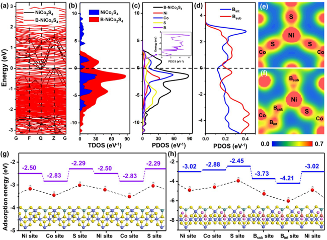
图9 (a)能带结构图;(b)NiCo2S4和B-NiCo2S4的总态密度图;(c)B-NiCo2S4的分波态密度图;(d)Bint和Bsub掺杂的态密度图;(e, f)NiCo2S4和B-NiCo2S4的电荷密度分布;(g)NiCo2S4和(h) B-NiCo2S4对OH−的吸附能[38]Fig. 9 (a) Band structures and (b) TDOS of NiCo2S4 and B-NiCo2S4. (c) PDOS of B-NiCo2S4. (d) DOS of Bint and Bsub. Charge density distributions of (e) NiCo2S4 and (f) B-NiCo2S4. Calculated OH− adsorption energies of (g) NiCo2S4 and (h) B-NiCo2S4[38]. Copyright 2022, American Chemical Society |
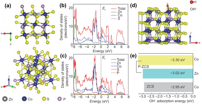
图10 (a)两个视角下的P-doped ZCS晶体结构;(b)ZCS和(c)P-doped ZCS的态密度图;(d)OH-在P-doped ZCS(200)面Co位点上的吸附示意图;(e)OH-在ZCS和P-doped ZCS不同位点上的吸附能[50]Fig. 10 (a) Crystalline structure of P-doped ZCS from two perspectives. DOS of (b) ZCS and (c) P-doped ZCS. (d) Diagrammatic sketch of the OH− adsorption on Co sites of the (200) facet of P-doped ZCS. (e) OH− adsorption energies of different sites in ZCS and P-doped ZCS[50]. Copyright 2021, Springer |
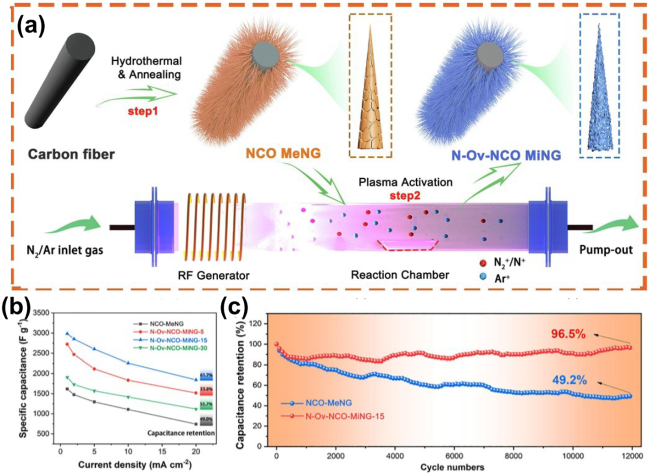
图13 (a)N-Ov-NCO MiNG-x电极的制备示意图;(b)不同电极材料在不同电流密度下的比电容;(c)样品在20 mA·cm−2下的循环性能[60]Fig. 13 (a) Schematic illustration for fabrication of the N-Ov-NCO MiNG-x. (b) Specific capacitances of the various electrodes at different current densities. (c) Cycling performance at the current density of 20 mA·cm−2 [60]. Copyright 2022, Elsevier |
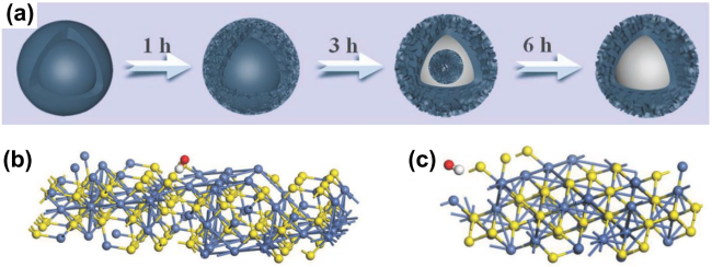
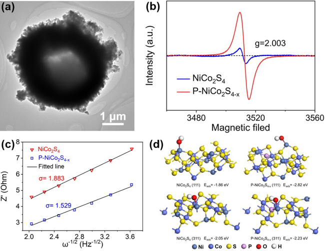
图14 (a)P-NiCo2S4−x HMSs的TEM图;(b)电子顺磁共振谱图;(c)低频区Z´对ω−1/2的线性拟合关系图;(d)密度泛函理论计算OH-在P-NiCo2S4−x和NiCo2S4的(311)和(111)面上的吸附能[61]Fig. 14 (a) The TEM image of P-NiCo2S4−x HMSs. (b) Electron paramagnetic resonance spectra. (c) Linear relationship between Z′ and ω−1/2 in the low-frequency region. (d) The adsorption energy of OH- in (311) and (111) planes for P-NiCo2S4−x and NiCo2S4 from density functional theory calculation[61]. Copyright 2023, Elsevier |
表1 Comparison of Electrochemical Performance Parameters of Electrode Materials Prepared by Different Control StrategiesTable 1 Comparison of electrochemical performance of electrode materials prepared by different modulation strategies |
| Materials | Capacity (F·g-1, 1 A·g-1) | Rate capability | Cyclic stability | Supercapacitor | Power denstity (Wh·kg-1) | Energy density (W·kg-1) | Ref |
|---|---|---|---|---|---|---|---|
| NiCo2O4 nanowire | 1283 F·g-1 at 1 A·g-1 | 79.0% at 20·A g-1 | 72. 7% after 2100 cycles at 1 A·g-1 | - | - | - | 15 |
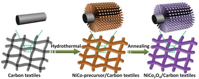
| NiCo2O4@Ni3S2 nanowire | 3.0 F·cm-2 at 5 mA·cm-2 | - | 93.3% after 10000 cycles at 1 A·g-1 | NiCo2O4@Ni3S2//AC | 5.81 W·cm-3 | 1.89 mWh·cm-3 | 16 |
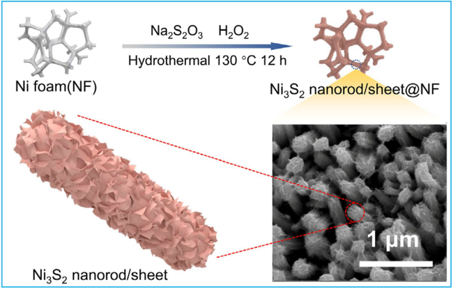
| Ni3S2 nanorod/sheet | 6.24 F·cm-2 at 5 mA·cm-2 | 85.7% at 20 A·g-1 | 85.7% after 3000 cycles at 15 mA·cm-1 | Ni3S2 RS//AC | 15.00 W·cm-3 | 1.16 mWh·cm-3 | 17 |
| NiCo2O4 nanoflower | 658 F·g-1 at 1 A g-1 | 78.0% at 20 A·g-1 | 93.5% after 10000 cycles at 5 A·g-1 | NiCo2O4//RGO | 650 | 23.9 | 18 |
| Ni/Co-LDH microspheres | 1652 F·g-1 at 1 A·g-1 | 87% at 25 A·g-1 | 100% after 2000 cycles at 5 A·g-1 | Ni/Co-LDH//AC | 74.3 | 32.9 | 19 |
| NiCo2O4 microtubes | 1387.9 F·g-1 at 1 A·g-1 | 62.2% at 30 A·g-1 | 89.4% after 12000 cycles at 10 A·g-1 | - | - | - | 20 |
| G/Ni-S-P | 1406 C·g-1 at 1 A·g-1 | 60.2% at 120 A·g-1 | 89.4% after 12000 cycles at 10 A·g-1 | G/Ni-S-P//graphene/FeOOH | 4.7 kW·kg-1 | 58.1 | 25 |
| NiSe2/CoSe2 | 171.5 mAh·g-1 at 1 A·g-1 | 60.8% at 50 A·g-1 | 109.8% after 5000 cycles at 10 A·g-1 | NiSe2/CoSe2//N,S-rGO HSC | 26.1 kW·kg-1 | 53.7 | 31 |
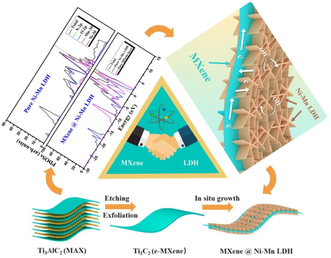
| LDH-MXene-LDH | 179 mAh·g-1 at 1 A·g-1 | 62.6% at 10 A·g-1 | 79.1% after 5000 cycles at 6 A·g-1 | MXene@Ni-Mn LDH//AC | 800 W·kg-1 | 44.7 | 32 |
| Ni2Co-LDHs@AL-Ti3C2 MXene | 227 mAh·g-1 at 1 A·g-1 | 55.5% at 150 A·g-1 | 90.0% after 10000 cycles at 10 A·g-1 | Ni2Co-LDHs@AL-Ti3C2 MXene//GO | 388 | 68.0 | 33 |
| Cu-Ni3S2 | 847 F·g-1 at 1 A·g-1 | 66.3% at 10 A·g-1 | 94.0% after 5000 cycles at 5 A·g-1 | Cu-Ni3S2//AC | 850 | 33.7 | 36 |
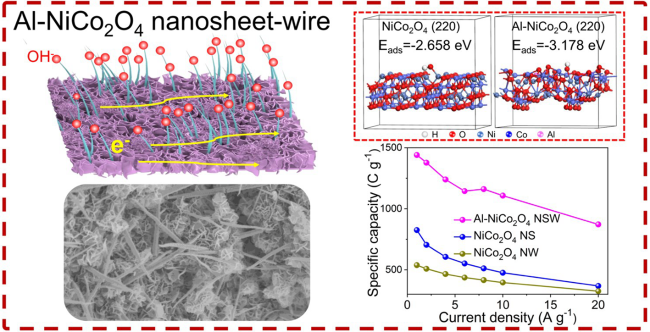
| Al-NiCo2O4 NSW | 1441 C·g-1 at 1 A·g-1 | 60.5% at 20 A·g-1 | 87.6% after 5000 cycles at 10 A·g-1 | Al-NiCo2O4 NSW//AC | 800 | 46.2 | 37 |
| B-NiCo2S4 | 738.0 C·g-1 at 1 A·g-1 | 72.9% at 10 A·g-1 | 98.5% after 5000 cycles at 5 A·g-1 | B-NiCo2S4//AC | 804 | 32.9 | 38 |
| S-NiFe2O4 | 284.0 F·g-1 at 1 A·g-1 | 82.0% at 10 A·g-1 | - | NFO-S//AC | 375 | 21.1 | 40 |
| P-NiCo2O4 | 2747.8 F·g-1 at 1 A·g-1 | 50% at 100 A·g-1 | 94.6% after 5000 cycles at 15 A·g-1 | P-NCO NWs/NF//RGO | 7750 | 28.2 | 48 |
| P-NiWO4@CoWO4 | 1683.4 F·g-1 at 1 A·g-1 | 88% at 10 A·g-1 | 84.0% after 1000 cycles at 1 mA cm-2 | P-NiWO4@CoWO4//AC | 825 | 26.8 | 49 |
| P-ZCS/HC | 1080 C·g-1 at 1 A·g-1 | 63.3% at 20 A·g-1 | 93.8% after 10000 cycles at 15 A·g-1 | P-ZCS/HC//RGO | 16 kW·kg-1 | 62.9 | 50 |
| Ov-Co3O4 /graphene | 978.1 F·g−1 at 1 A·g−1 | 93.7% at 10 A·g-1 | 99.3%% after 20000 cycles at 10 A·g-1 | - | - | - | 54 |
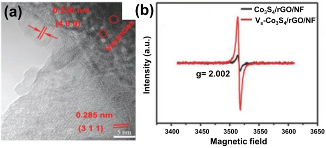
| VS-Co3S4/rGO/NF | 2615 F·g−1 at 1 A·g−1 | 51.8% at 20 A·g-1 | 70.2%% after 5000 cycles at 30 A·g-1 | VS-Co3S4/rGO/NF//AC | 850 | 43.8 | 55 |
| Ni3S4−x HMs | 1884 F·g-1 at 2 A·g-1 | 85.6% at 10 A·g-1 | 97.9% after 10000 cycles at 10 A·g-1 | Ni3S4−x HMs//AC | 1.68 kW·kg-1 | 33.1 | 56 |
| Fe-CoNi2S4−x | 2779.6 F·g-1 at 1 A·g-1 | 58.5% at 10 A·g-1 | 78.0% after 5000 cycles at 10 A·g-1 | Fe-NiCo-S//GO | 847 | 56.0 | 58 |
| N-Ov-NCO MiNG | 2986.3 F·g-1 at 1 mA·cm-2 | 53% at 10 A·g-1 | 96.5% after 12000 cycles at 1 mA·cm-2 | N-Ov-NCO MiNG-15//AC | 748 | 103.2 | 60 |
| P-NiCo2S4−x | 1146.0 C·g-1 at 1 A·g-1 | 61.8% at 30 A·g-1 | 79.5% after 20000 cycles at 10 A·g-1 | P-NiCo2S4−x //AC | 867 | 62.7 | 61 |
| [1] |
|
| [2] |
|
| [3] |
|
| [4] |
|
| [5] |
|
| [6] |
|
| [7] |
|
| [8] |
|
| [9] |
|
| [10] |
|
| [11] |
|
| [12] |
|
| [13] |
|
| [14] |
|
| [15] |
|
| [16] |
|
| [17] |
|
| [18] |
|
| [19] |
|
| [20] |
|
| [21] |
|
| [22] |
|
| [23] |
|
| [24] |
|
| [25] |
|
| [26] |
|
| [27] |
|
| [28] |
|
| [29] |
|
| [30] |
|
| [31] |
|
| [32] |
|
| [33] |
|
| [34] |
|
| [35] |
|
| [36] |
|
| [37] |
|
| [38] |
|
| [39] |
|
| [40] |
|
| [41] |
|
| [42] |
|
| [43] |
|
| [44] |
|
| [45] |
|
| [46] |
|
| [47] |
|
| [48] |
|
| [49] |
|
| [50] |
|
| [51] |
|
| [52] |
|
| [53] |
|
| [54] |
|
| [55] |
|
| [56] |
|
| [57] |
|
| [58] |
|
| [59] |
|
| [60] |
|
| [61] |
|
/
| 〈 |
|
〉 |