Home Journals Progress in Chemistry
Progress in Chemistry

Abbreviation (ISO4): Prog Chem      Editor in chief: Jincai ZHAO

About  /  Aim & scope  /  Editorial board  /  Indexed  /  Contact  / 
综述

Single Crystallization of Layered Nickel-Rich Cathode Materials

  • Luqi Hao 1, 2 ,
  • Xinyu Zhu 1, 2 ,
  • Yongjian Li 1, 2 ,
  • Qing Huang 1, 2 ,
  • Ning Li , 1, 2, * ,
  • Yuefeng Su 1, 2
Expand
  • 1 School of Material Science and Engineering, Beijing Institute of Technology, Beijing 100081, China
  • 2 Chongqing Innovation Center, Beijing Institute of Technology, Chongqing 401120, China

Received date: 2024-03-01

  Revised date: 2024-05-22

  Online published: 2024-07-01

Abstract

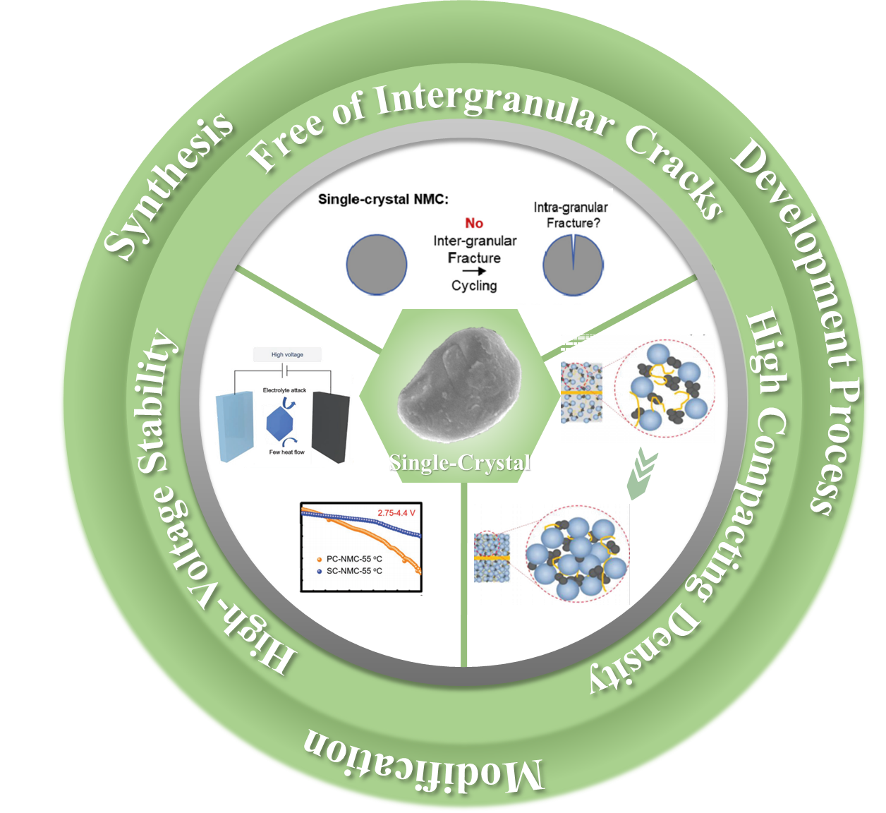
Nickel-rich-manganese-cobalt oxide (NMC) ternary cathode materials are considered to be one of the most promising cathode materials for lithium-ion batteries due to their high specific capacity and high power. However, most of the current nickel-rich ternary layered materials are polycrystalline particles, and their volumetric energy density and cyclic stability are not satisfactory. Therefore, independent and well-dispersed single-crystal nickel-rich ternary layered materials (SC-NMCs) can be used as the best candidates to replace polycrystalline nickel-rich ternary cathodes. In this paper, we systematically review how to synthesize SC-NMCs and their corresponding relationship with the properties of single-crystal from the perspectives of precursor preparation, material sintering and lithium salt supplementation. Secondly, the performance advantages of SC-NMCs compared with polycrystalline materials are comprehensively summarized, especially the morphology without cracks between particles, which shows good cycling performance. Thirdly, in view of the disadvantages and challenges of the current SC-NMCs, the modification strategies of SC-NMCs, such as element doping, surface modification and double modification, are comprehensively introduced. This review puts forward innovative views on the synthesis and modification of SC-NMCs and provides directional guidance for the application and development of single-crystal nickel-rich ternary layered cathode materials for next-generation lithium-ion batteries.

Contents

1 Introduction

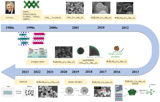
2 The development process of SC-NMCs

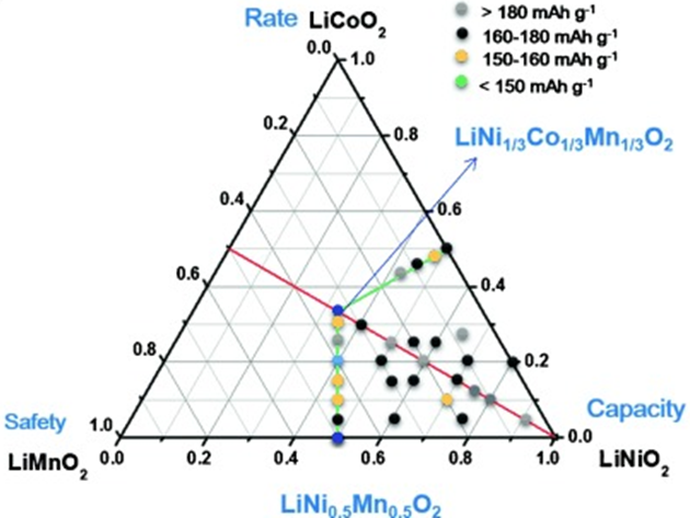
2.1 From low to high nickel

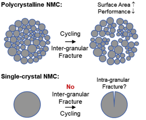
2.2 From PC-NMCs to SC-NMCs

3 Basic properties and advantages of SC-NMCs

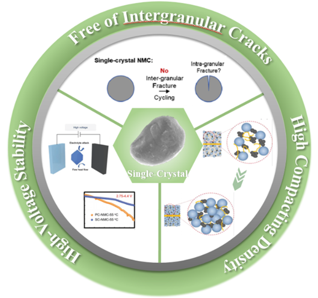
3.1 Free of intergranular cracks

3.2 High compacting density

3.3 High-voltage stability

4 The synthesis of SC-NMCs

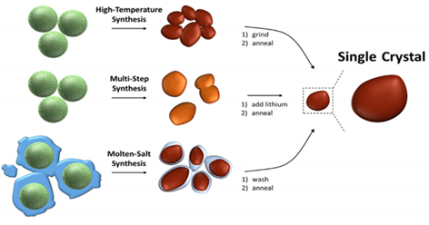
4.1 Solid-phase reaction high-temperature calcination

4.2 Multi-step calcination

4.3 Molten-salt method

5 The modification of SC-NMCs

5.1 Elemental doping

5.2 Coating

5.3 Double modification

6 Conclusion and outlook

Cite this article

Luqi Hao , Xinyu Zhu , Yongjian Li , Qing Huang , Ning Li , Yuefeng Su . Single Crystallization of Layered Nickel-Rich Cathode Materials[J]. Progress in Chemistry, 2024 , 36(10) : 1581 -1593 . DOI: 10.7536/PC240301

1 Introduction

Lithium-ion batteries, with their advantages of high capacity, light weight, environmental friendliness, and safety, are widely used in electronic devices and electric vehicles, especially the cathode materials play a crucial role in lithium-ion batteries[1,2]. However, using only LiFePO4, LiMn2O4, LiCoO2, etc., as cathode materials to achieve the goal of high energy density remains a challenge. High-nickel lithium nickel manganese cobalt oxide (NMC) ternary cathode active materials, combining the advantages of LiNiO2, LiCoO2, and LiMnO2, have features such as high specific capacity, high power, and long cycle life, and are becoming the preferred cathode material for the next generation of lithium-ion batteries[3~5].
Most of the high-nickel ternary cathode material products on the market are polycrystalline secondary particles aggregated from anisotropic primary particles. Although polycrystalline high-nickel ternary layered material particles exhibit good capacity and rate performance, during the charging and discharging process, the polycrystalline particle structure can fracture (i.e., intergranular cracks occur). The breakage between particles disrupts the electronic and ionic conduction pathways, also increases the particle surface area, exacerbating side reactions with the electrolyte. As a result, their volumetric energy density and cycle stability are not satisfactory[6~10]. Therefore, independent and well-dispersed single-crystal high-nickel ternary layered materials can serve as a solution for the further development of batteries with high energy density and excellent cycle stability.
This paper is mainly based on the development process of single-crystal high-nickel ternary layered materials, detailing the performance advantages, synthesis methods, and existing challenges of single-crystal high-nickel ternary layered materials. It innovatively explores the difficulties in synthesizing single-crystal high-nickel ternary layered materials from the perspective of precursor particle size. Regarding the modification methods and mechanisms to improve the performance of single-crystal high-nickel ternary layered materials, it reviews the characteristics and research progress of different modification strategies, including element doping, surface modification, and multiple modifications. The aim is to highlight the advantages brought by the unique morphology of single-crystal high-nickel ternary layered materials, providing a reference for their applications.

2 Development Progress of Single-Crystal High-Nickel Ternary Layered Cathode Materials

2.1 From Low Nickel to High Nickel

In 1980, Goodenough et al.[11] proposed the layered oxide LiCoO2, making the first attempt to use lithium cobalt oxide as a cathode for batteries, after which lithium-ion batteries were introduced. Subsequently, a series of layered oxide materials (LiCoO2, LNO, Li2MnO3), spinel-structured materials (LiM2O4, M=Mn, Ni, Co), and olivine materials (LiMPO4, M=Fe, Co, Ni, Mn) have been extensively researched and developed[12~15]. However, single-layered oxide materials, along with spinel and olivine-structured materials, suffer from issues such as low capacity and poor stability, making it difficult for them to be widely used commercially. In contrast, ternary layered oxide cathode materials (LiNi1−xyCoxMnyO2) possess higher capacities, especially high-nickel ternary layered oxide cathode materials (where 1−xy>0.6 is referred to as high nickel), which have attracted attention due to their high reversible capacity, low cost, and environmental friendliness, and have found applications in the portable electronics and electric vehicle industries (Figure 1).
图1 单晶高镍三元层状正极材料发展时间轴示意图[11,12,17,29,33,34,36 ~45]

Fig. 1 Timeline of development of single crystal nickel-rich ternary layered cathode materials[11,12,17,29,33,34,36 ~45]

In early lithium-ion batteries, LiNiO2was not commercialized for several reasons, such as the very stringent preparation conditions required for synthesis and the volatility of lithium in the reaction mixture leading to poor reproducibility of material performance. On the other hand, LiCoO2became the primary cathode material due to its high theoretical capacity; however, the low lithium ion utilization rate and the actual specific capacity of around 160 mAh·g−1of LiCoO2limited its further development, as its overall performance did not meet the ideal requirements people had for batteries. After 2000, with the surge in global electric vehicles, new opportunities for nickel-based cathode materials in lithium-ion batteries emerged: the demand for low-cost, high-energy rechargeable lithium-ion batteries could be met by nickel-containing cathode materials. Based on partially substituting nickel with other cations to maintain high energy density, researchers systematically studied the ternary system of LiNi1− x yCo xMn yO2, synthesizing new oxides where cobalt and manganese act as substituents (or dopants), reducing the total fraction of nickel. The resulting solid solution is known as nickel-manganese-cobalt oxide (NMC). These three transition metals play different roles in the crystal structure and electrochemical properties of the material. Generally, Ni ions provide most of the reversible capacity; Co ions reduce cationic mixing, strengthening the layered structure; on the other hand, although Mn ions do not participate in the redox process, they stabilize the local structure of the material[16~20].
In 2001, Ohzuku and Makimura[17]proposed the LiNi1/3 Co1/3Mn1/3O2compound as a highly promising cathode material for lithium-ion batteries, characterized by high capacity, structural stability, and good cycling performance. As the nickel content in ternary layered oxide cathodes increases, so does the specific capacity of the material. With the market's increasing demand for higher capacities, the development trend of ternary cathode materials has gradually shifted towards high-nickel and low-cobalt compositions. Researchers have already developed several promising next-generation, high-energy-density ternary cathode materials for lithium-ion batteries, such as LiNi0.5Co0.2Mn0.3O2, LiNi0.6Co0.2Mn0.2O2, LiNi0.7 Co0.15Mn0.15O2, LiNi0.8Co0.1Mn0.1O2, and high-nickel NCM9 series materials currently under development (Figure2)[21~29]. However, most of these ternary layered oxide cathode materials with varying nickel contents are in polycrystalline form, and polycrystalline high-nickel materials still face certain issues.
图2 不同化学计量比的LiNixCoyMnzO2的性能三相图[29]

Fig. 2 Three phase diagram of performance of LiNixCoyMnzO2 with different stoichiometric ratios[29]. Copyright 2015, Elsevier

2.1 From Polycrystalline to Single Crystal

Under ideal battery charge-discharge cycle conditions, Li+transports between the positive and negative electrodes without any irreversible losses. However, in practical situations, during repeated Li+deintercalation, due to anisotropic volume changes and internal stresses between primary particles, traditional polycrystalline NMC will develop intergranular microcracks that gradually expand from the surface to the interior, leading to more material area contacting the electrolyte, causing side reactions, capacity decay, and ultimately leading to the failure of polycrystalline NMC. A promising approach to alleviate these issues is the synthesis of single-crystal NMC materials (SC-NMCs). Single-crystal NMC has independent micron-sized particles rather than being composed of many nanoscale particles aggregated into micron-sized particles as in conventional polycrystalline cathode materials. Additionally, the single-crystal morphology reduces the generation of intergranular cracks, effectively limiting surface side reactions and continuous particle cracking, thereby greatly improving the cycling life of lithium-ion batteries. At the same time, the non-porous and high-strength nature of single crystals also allows for higher compaction density, significantly increasing the energy density of the battery[30~35]. Single-crystal cathode materials were introduced at the end of the 1990s and the beginning of the 21st century, and in recent years, the number of reports on the single-crystal morphology of layered ternary cathode materials has rapidly increased (Figure 1). Fu et al.[36]synthesized single-crystal LiNi1/3Co1/3Mn1/3O2hexagonal nanobricks using hexagonal nanoplates of LiNi1/3Co1/3Mn1/3O2as templates and precursors, which exhibited excellent cycling performance, providing guidance for the synthesis of layered NMC cathode materials with high discharge capacity and excellent rate performance (Figure 3a). Li et al.[37]synthesized single-crystal LiNi0.5Mn0.3Co0.2O2with grain sizes of 2-3 μm, which showed better capacity retention than polycrystalline materials at 40 and 55 ℃, 3-4.4 V, and the single-crystal material had a strong ability to suppress oxygen loss below 100 ℃ (Figure 3b). Wang et al.[38]successfully prepared single-crystal LiNi0.6Co0.2Mn0.2O2material through a hydrothermal-high-temperature solid-state method. This sample not only had uniform, well-crystallized particle morphology (850 ℃), but it also showed a first-week discharge specific capacity of 165.2 mAh·g−1at 0.2 C, 2.8-4.3 V, and after 100 cycles, the discharge specific capacity was 153.6 mAh·g−1, maintaining good capacity. It also had high capacity retention at high operating voltages (4.6 V) (Figure 3c)[39]. Xu et al.[40]prepared micrometer-sized secondary particles composed of single-crystal primary particles of LiNi0.8Co0.1Mn0.1O2through a co-precipitation-high-temperature solid-state method. This material exhibited excellent reversible capacity, with a first-week discharge specific capacity of 203.4 mAh·g−1at 3.0-4.3 V, and almost no capacity decay after 300 cycles, showing good cycling stability. Consistent crystal orientation can alleviate volume changes during charge-discharge cycles, thus significantly reducing the intergranular stress caused by volume changes (Figure 3d). The comprehensive performance of single-crystal high-nickel ternary layered cathode materials is excellent, attracting increasing attention from researchers[41~45].
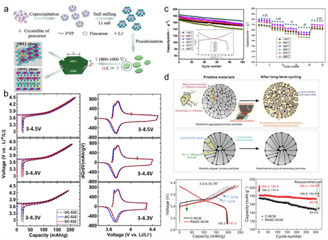
图3 (a) 单晶LNMC111纳米砖制备示意图[36];(b) 不同电压下单晶NMC532与多晶电化学性能示意图[37];(c) 单晶NMC622电化学性能示意图[38];(d) RASC-NMC材料的结构特性和电化学性能示意图[40]

Fig. 3 (a) Schematic diagram of preparing single-crystal LNMC111 nanobricks[36]. Copyright 2013, Elsevier. (b) Schematic diagram of electrochemical performance of single crystal NMC532 and polycrystal at different voltages[37]. Copyright 2017, Elsevier. (c) Schematic diagram of electrochemical performance of single crystal NMC622[38]. Copyright 2016, Elsevier. (d) Schematic diagram of structural properties and electrochemical properties of RASC-NMC materials[40]. Copyright 2019, Elsevier

3 Fundamental Properties and Advantages of Single-Crystal High-Nickel Ternary Layered Cathode Materials

Thanks to their unique morphology, SC-NMCs exhibit significant advantages over polycrystalline NMCs (PC-NMCs) with the same composition. (1) In terms of long-term cycling stability, individual SC-NMC particles show no intergranular cracks. (2) Regarding high-voltage performance, SC-NMCs also demonstrate excellent crack resistance under high voltage, leading to fewer side reactions and better capacity retention. (3) In terms of high energy, the non-porous and high-strength SC-NMCs exhibit a competitive higher compaction density and volumetric energy density in practical applications (Figure 4)[46~48].
图4 单晶高镍三元层状正极材料优势图[31,33,64]

Fig. 4 Schematic diagram of advantages of single crystal nickel-rich ternary layered cathode materials[31,33,64]

3.1 Inhibition of Microcracks

Microcracks are divided into two types: intragranular cracks and intergranular cracks. The reasons for the formation of intergranular cracks are as follows: during charging, Li+ is extracted from the lattice, the supporting effect of the Li layer disappears, leading to contraction along the c axis direction, while the opposite occurs during discharging. In this process, the lattice structure is prone to collapse along the c axis direction[49~52]. As shown in Figure 5, in polycrystalline materials, each primary particle is oriented randomly, and when the volume of the lattice changes, the direction of the anisotropic deformation produced by the primary particles is random. Some primary particles will push against each other, generating significant stress, while others will separate and lose contact. These phenomena lead to cracking both intergranularly and intragranularly. However, in micron-sized single-crystal materials, the particles are separated from each other, fundamentally avoiding the generation of intergranular microcracks and further preventing the formation of interconnected crack channels.
图5 多晶和单晶颗粒微裂纹产生示意图[31]

Fig. 5 Schematic diagram of microcrack generation in polycrystalline and single-crystal particles[31]. Copyright 2020, Elsevier

Inter-particle cracking may be a more severe factor in failure issues. Once microcracks form, the electrolyte can enter the interior of secondary particles through these microcrack channels, generating more active sites for side reactions. Moreover, the damage to the internal structure of the particles by the electrolyte is irreversible; once damage occurs, the cracks will only become more severe, eventually leading to the disintegration and degradation of particles from the surface to the bulk, thereby reducing the cycle stability of the battery. At the same time, the reaction between the electrolyte and the cathode material produces a NiO-like rock-salt phase, increasing the impedance of the cathode material. The diffusion of Li+ between the electrolyte and the cathode material is impeded, affecting the uniformity of the state of charge, leading to the generation of more cracks, and ultimately impacting the electrochemical performance[53~56].
In summary, unlike conventional PC-NMCs, SC-NMCs effectively suppress the damage caused by intergranular microcracks due to their unique morphology and inherent structural stability. In addition, the independent particle surface reduces side reactions and phase transitions at the electrolyte-cathode material interface, which helps to optimize the battery's cycling performance.

3.2 High Compaction Density

Compaction is a low-cost process that can increase the volumetric energy density of batteries by reducing porosity from 50% to 70% down to 20% to 40%, and it also enhances the bonding strength between active materials, conductive carbon, binder, and current collector[33]. Furthermore, batteries for different applications such as 3C electronic products, electric vehicles, and hybrid vehicles require varying levels of volumetric energy density, thus necessitating different compaction densities. Within a moderate range, the higher the compaction density of the material, the greater the capacity of the battery. In commercial cathode materials, LiCoO2 dominates in portable electronic devices due to its high compaction density and high volumetric energy density. The compaction density of LiCoO2 can reach up to 3.9 g·cm−3, whereas the compaction density of PC-NMCs, which consist of tiny spherical secondary particles, is only close to 3.4 g·cm−3. Therefore, increasing compaction density is a highly promising direction for the development of new materials to broaden their application fields[57~59].
The size of polycrystalline particles is generally about 10~20 μm, and due to the squeezing between adjacent larger particles, they cannot withstand high compaction pressures. Monocrystalline particles range from 2~8 μm, and an appropriate particle size distribution and excellent structural strength help the material withstand stress during compaction and avoid structural collapse[60~62]. Compared with PC-NMCs, non-porous SC-NMCs have micron-sized primary particles, consistent lattice orientation, and high density, which allows them to withstand greater forces without breaking during compaction, thereby achieving higher structural stability and compaction density, further improving their volumetric energy density. Therefore, appropriately sized SC-NMC particles contribute to obtaining relatively high compaction density and volumetric energy density.

3.3 High Voltage and Thermal Stability

To address the issue of relatively low capacity in high-nickel ternary cathode materials, researchers have proposed two strategies to enhance their energy density: one is to increase the Ni content (x>0.8), and the other is to broaden the potential window (>4.4 V). However, raising the upper cutoff voltage poses a severe challenge to the structural and thermal stability of PC-NMCs cathode materials. This is because increasing the upper cutoff voltage not only elevates the average valence state of transition metals, accelerating the interfacial reactions between active Ni3+/Ni4+on the particle surface and the electrolyte, leading to the formation of the cathode electrolyte interface (CEI) film; but also promotes cation mixing and the phase transformation from layered structure to rock-salt structure[63,64]. Meanwhile, PC-NMCs with high nickel content experience structural changes and crack formation in the high-voltage region, further resulting in rapid capacity and voltage decay during cycling, as well as irreversible structural damage.
For SC-NMCs, the issues caused by the H2→H3 phase transition are effectively reduced, resulting in limited volume changes of the material during Li+ deintercalation. Additionally, SC-NMCs effectively suppress the formation of the spinel phase, thereby limiting voltage decay and maintaining stability during cycling. Therefore, SC-NMCs materials achieve superior high-voltage stability and high capacity[65~67].

4 Synthesis of Single-Crystal High-Nickel Ternary Layered Cathode Materials

Although single-crystal materials have many advantages, their current synthesis conditions are harsh and the process is unstable, making them more complex to synthesize than polycrystalline materials. Additionally, it is necessary to control the morphology, size, and uniform distribution through synthesis conditions to achieve superior performance. The preparation of single-crystal materials typically requires the prior preparation of precursors. Methods for preparing single-crystal precursors include co-precipitation, sol-gel, and hydrothermal methods. The larger the precursor particle size, the easier it is to sinter into a single crystal; however, excessively large precursor particles are difficult to fully fuse into a single crystal during the sintering process. Therefore, during the precursor preparation stage, it is necessary to control the pH, reaction temperature, stirring speed, feeding rate, and raw material concentration to synthesize precursor particles with suitable sizes, which will facilitate the formation of single-crystal materials with appropriate grain sizes after calcination. Moreover, increasing the calcination temperature is the most effective method for controlling the morphology of single crystals, as shown in Figure 6. After drying, the precursors are sintered, generally using high-temperature solid-state or molten salt-assisted sintering methods. The essence of both methods is to break, dissolve, recrystallize, and grow secondary particles through a melting-recrystallization process[31,68,69].
图6 单晶合成方式示意图[70]

Fig. 6 Schematic diagram of single crystal synthesis[70]. Copyright 2021, Elsevier

4.1 High-Temperature Solid-State Reaction Method

Solid-phase reactions involve thoroughly mixing solid-state precursors with a certain proportion of lithium salts, followed by uniform grinding, and then high-temperature calcination. A calcination temperature that is too low is insufficient to produce oxides with appropriate phase purity and crystallinity. After increasing the calcination temperature, larger single-crystal particles begin to appear at high temperatures. At the same time, during heating or calcination, additional grinding can break up agglomerates and expose a large number of new surfaces, thereby enhancing grain boundary diffusion capabilities[64,70]. In summary, changing the state of the solid precursor materials and increasing the calcination temperature can alleviate agglomeration, improve crystallinity, and facilitate the synthesis of single-crystal particles. Additionally, when the temperature rises, it is necessary to increase the excess amount of lithium to offset the volatilization of lithium at high temperatures.
In the preparation of single-crystal samples, the preparation of precursors and the high-temperature solid-state process are similar to those for polycrystals. Su et al.[53] first calcined at 900 ℃ for 10 h to obtain polycrystalline Li1.2Mn0.54Ni0.13Co0.13O2. Subsequently, after ball milling for 1 h, heating at 500 ℃ for 5 h yielded single-crystal particles of Li1.2Mn0.54Ni0.13Co0.13O2.

4.2 Multi-step Calcination Method

Calcination at high temperatures and long holding times usually causes the primary particles formed after pre-decomposition to fuse, thus forming larger and smoother particle surfaces. The primary particles grow larger at higher calcination temperatures; therefore, materials calcined at too low a temperature are insufficient to form larger single-crystal particles. At the same time, the smaller particles obtained from low-temperature calcination can better accommodate internal stresses during the charge-discharge process, exhibiting higher discharge capacity and better rate performance, and demonstrating superior cycle stability. Therefore, multi-step calcination can optimize grain growth and crystal structure, thereby obtaining single-crystal particles with suitable particle size and low cation mixing degree[71~75].
Wang et al.[38] synthesized single-crystal LiNi0.6Co0.2Mn0.2O2 material using a multi-step calcination method, calcining for 3 h at 550, 700, and 750 ℃ in an oxygen atmosphere, followed by heating to 900 ℃ for 12 h of calcination, and then annealing at different temperatures. The results showed that as the annealing temperature increased, the size of the single-crystal particles gradually increased. When the annealing temperature rose to 850 ℃, the single-crystal particle size increased, and the crystallization effect was better, resulting in uniform single-crystal particles with a diameter of 800 nm. Subsequently, it underwent electrochemical testing, with the initial discharge capacity reaching 183.7 mAh·g−1, a coulombic efficiency >90.0%, and after 100 cycles, a capacity retention rate of up to 89.9%. Moreover, the single-crystal LiNi0.6Co0.2Mn0.2O2 also exhibited excellent performance at high operating voltages (4.6 V).

4.3 Molten Salt Method

One of the potential benefits of molten salt synthesis is that it can influence the particles after calcination by altering the amount and composition of the salt. In this method, a large amount of salt, often several times the amount of the precursor, is added to the precursor during the calcination process. Therefore, the selected salt must be stable and have a sufficiently low melting point, which is typically achieved by using eutectic mixtures of multiple salts. Additionally, the molten salt must have appropriate solution properties. In the molten salt, atoms may dissolve and diffuse, providing additional pathways for crystal growth, which usually reduces the calcination temperature required to achieve a given particle size, thereby decreasing cation disorder and particle agglomeration. However, this method requires washing after calcination to remove excess salt[31,70].

5 Modification of Single-Crystal High-Nickel Ternary Layered Cathode Materials

Single-crystal high-nickel ternary cathode materials have three significant advantages over polycrystalline materials, but currently, their synthesis conditions are harsh, and there are issues such as restricted Li+ diffusion kinetics and intragranular microcracks. In addition, similar to polycrystalline high-nickel materials, single-crystal high-nickel ternary cathode materials also face problems of severe cation mixing and increased electrolyte side reactions under high nickel or high voltage states.
Single-crystal high-nickel ternary cathode materials, although free from the intergranular microcrack issues seen in polycrystalline high-nickel materials, encounter another problem under high-voltage applications, namely the appearance of intragranular microcracks. Due to the robust structure of single-crystal materials, generally, microcracks in single-crystal materials are more likely to occur under overcharging or at high temperatures[76]. Additionally, during the battery cycling phase, a large number of vacancies are generated as Li+ is deintercalated during charging, which reduces the migration energy barrier for transition metal ions. Some Ni2+ will spontaneously migrate to the Li layer, occupying the positions of Li+. This site defect leads to cation mixing, hindering the insertion of Li+ and causing capacity decay. As the degree of cation mixing increases, the surface structure undergoes a transformation from a layered structure to a spinel structure, ultimately forming a rock-salt phase. The rock-salt phase further impedes the diffusion of Li+, reducing the rate performance of single-crystal high-nickel materials. Furthermore, side reactions that occur during the charge-discharge process gradually affect battery performance. These include the reaction of high-nickel materials with H2O and CO2 in the air when exposed, leading to the formation of LiOH, LiHCO3, and Li2CO3 coatings on the particle surfaces[76~78]. To alleviate these issues, researchers have proposed some modification methods (Table 1) to improve the performance of lithium-ion batteries, such as bulk doping and surface coating, to enhance the overall performance of single-crystal high-nickel ternary cathode materials.
表1 不同改性方式改进单晶高镍正极材料电化学性能总结

Table 1 Summary of electrochemical properties of monocrystalline high nickel cathode materials improved by different modification methods

modification method Initial discharge specific capacity(mAh·g-1) Xth discharge specific capacity(mAh·g-1) Xth capacity retention rate
Nb doping[86] 204.0 174.4 85.5%(150)
Al/Zr doping [87] ∼192.0 ∼176.8 92.1%(100)
Al/Ti doping [88] 197.7 185.4 93.8%(100)
TiO2 coating[94] ∼187.0 176.2 94.2%(200)
Li3PO4 coating [95] 250.0 187.0 74.8%(100)
LiF coating [96] ∼170.0 ∼139.7 82.2%(200)
Li2TiO3 coating
+Ti doping[100]
175.9 155.7 88.5%(100)
B2O3/Li3BO3 coating
+B3+doping[85]
208.8 182.5 87.4%(150)
Al/Zr co-doping
(Li2ZrO3+Al doping)[101]
221.6 163.0 73.6%(150)

5.1 Element Doping

The migration of transition metal ions into the lithium layer is a common issue, which can lead to the gradual transformation of the material from a layered structure to a spinel phase or even a rock salt phase, thereby causing capacity decay and reduced cycling stability. Ion doping can suppress Li+/Ni2+ mixing, reduce the formation and migration of Ni2+, thereby strengthening the lattice structure, alleviating the H2→H3 phase transition, and maintaining the stability of the crystal structure.
The synthesis of metal ion-doped materials is simple, and their application range is wide, such as Al3+, Mg2+, Ti4+, Nb5+, Zr4+, etc., which have received extensive attention in single-crystal high-nickel ternary cathode materials[79~85]. Zhang et al.[86] determined the effects of Nb5+, Sr2+, and Y3+ cation doping on single-crystal LiNi0.7Co0.1Mn0.2O2 through a rapid screening method, and focused on the impact of Nb5+ doping on structural stability. The Nb5+-doped single-crystal LiNi0.7Co0.1Mn0.2O2 (Nb-NMC) enhanced structural stability and improved electrochemical performance. After 150 cycles, the capacity retention rate was 85.5% (1 C, 3.0~4.5 V). Even at high temperatures (45 ℃), the structure of Nb-NMC remained stable, with a capacity of 149.8 mAh·g−1 after 100 cycles (Figure 7a).
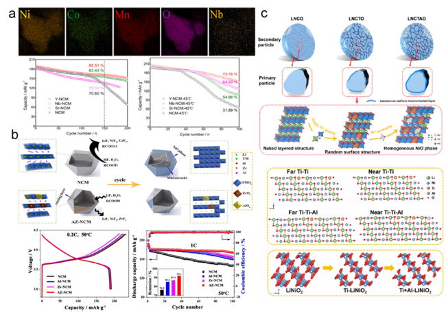
图7 (a)Nb5+掺杂样品的EDS以及Nb5+、Sr2+、Y3+掺杂样品不同温度下的循环性能示意图[86];(b)Al/Zr共掺杂的协同效应示意图[87];(c)Ti/Al共掺杂构型示意图[88]

Fig. 7 (a) Schematic diagram of cyclic performance before and after Nb ion doping[86]. Copyright 2021, Elsevier. (b) Schematic diagram of the synergistic effect of Al/Zr co-doping[87]. Copyright 2021, Elsevier. (c) Schematic diagram of Ti/Al co-doping[88]. Copyright 2020, Elsevier

A single dopant ion at a single site may disrupt the structural balance of the bulk material, while selecting different dopant ions can exert a synergistic effect. Feng et al.[87] prepared Al and Zr co-doped single crystal LiNi0.6Co0.2Mn0.2O2, with the optimized cathode material also exhibiting good structural stability and cycling performance at high temperatures. At 50 ℃, after 100 cycles, the capacity retention rate of the Al/Zr co-doped sample reached 92.1% (1 C, 3.0~4.4 V), significantly higher than that of the singly doped Al sample (85.4%), singly doped Zr sample (87.1%), and undoped sample (76.3%) (Figure 7b). Wu et al.[88] utilized the synergistic effect of Ti and Al co-substitution to optimize the surface structural distribution of high-nickel cathode materials. Compared to single Ti doping, the addition of a small amount of Al effectively dispersed the distribution of Ti4+, regulated the ordered distribution of Ni2+, thereby alleviating the randomness of the surface structure composition and forming a thinner surface rock-salt phase reconstruction layer. This uniform rock-salt phase, combined with strong Ti—O and Al—O bonds, generated a reversible H2→H3 phase transition, further eliminating irreversible phase transitions (Figure 7c).

5.2 Coating

The surface stability of single-crystal high-nickel ternary cathode materials has always been considered a key factor in their electrochemical performance. Coating modification is one of the most commonly used methods for single-crystal high-nickel ternary cathode materials, and the principle typically involves forming a physical protective film on the surface of the cathode material using electrochemically inactive or active substances to prevent direct contact between the material and the electrolyte, thereby inhibiting side reactions at the interface between the cathode material and the electrolyte[89].
Commonly used surface coating materials for single-crystal high-nickel ternary cathode materials include oxides such as Al2O3, TiO2, ZrO2, Co3O4; phosphates such as Li3PO4, LaPO4, FePO4; fluorides such as LiF, AlF3; and carbon[89~93]. These coating materials are mainly electrochemically or chemically inactive inorganic coatings, such as metal oxides, which can effectively prevent the electrode surface from coming into contact with organic electrolytes, thereby mitigating electrolyte decomposition and reducing the formation of byproducts. Additionally, carbon material coatings can improve the cycle life and fast charging capability of single-crystal high-nickel ternary cathode materials by inhibiting side reactions and enhancing the electronic conductivity of the materials.
You et al.[94] synthesized single-crystal LiNi0.65Co0.15Mn0.2O2 (S-NMC65) with a diameter of 3~5 μm and modified its surface with nano-TiO2 (5TS-NMC65), which improved the surface stability and further enhanced the cycling performance during charge and discharge processes. After 200 cycles at 25 ℃, S-NMC65 had a capacity retention rate of only 86.0%, while 5TS-NMC65 showed a capacity retention rate as high as 94.2% (1 C, 3.0~4.5 V). Under the same conditions, when the temperature was raised to 55 ℃, S-NMC65 had a capacity retention rate of only 87.6% after 125 cycles, whereas 5TS-NMC65 maintained a capacity retention rate of 93.3% (Figure 8a). Karan et al.[95] coated a thin layer of Li3PO4 on the surfaces of LiNi1/3Mn1/3Co1/3O2 (NMC333) and LiNi0.5Mn0.3Co0.2O2 (NMC532). The Li3PO4 coating was very effective in improving the initial discharge specific capacity and the rate performance in subsequent charge-discharge cycles for NMC333 and NMC532. The discharge specific capacity of the modified NMC532 increased to 250.0 mAh·g−1, 90.0 mAh·g−1 higher than that of the bulk material. Meanwhile, the Li3PO4-coated NMC532 exhibited a specific capacity of 187.0 mAh·g−1 after 100 cycles at 1 C, while the bulk material had only 50.0 mAh·g−1 (Figure 8b). Additionally, some coating materials reduce the acidity of the electrolyte by reacting with HF to produce H2O, thereby decreasing the side reactions between high-nickel cathode materials and excess HF. Xiong et al.[96] reported that LiF-modified LiNi0.8Co0.1Mn0.1O2 experienced a capacity loss of only 17.8% after 200 cycles, about 10.0% lower than that of the bulk material, and the improvement in cycling performance was even more pronounced at 60 ℃. LiF acted as an HF inhibitor during the cycling process, so compared to the bulk material, LiF-modified LiNi0.8Co0.1Mn0.1O2 demonstrated superior rate and cycling performance (Figure 8c).
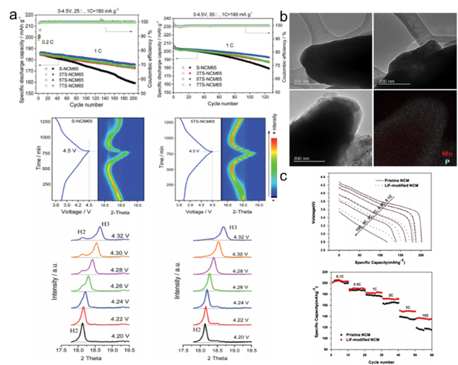
图8 (a)纳米TiO2包覆循环性能以及原位XRD示意图[94];(b)Li3PO4包覆TEM示意图[95];(c)LiF改性电化学性能示意图[96]

Fig. 8 (a) Schematic diagram of cycling performance of nano TiO2 before and after coating[94]. Copyright 2022, Elsevier. (b) Schematic diagram of Li3PO4 coating TEM[95]. Copyright 2019, Elsevier. (c) Schematic diagram of electrochemical performance of LiF modification[96]. Copyright 2013, Elsevier

5.3 Dual Modification

Surface modification can only prevent the further expansion of cracks and the destruction of surface structures, but it cannot solve issues such as lattice body phase transition and cation mixing. Therefore, dual modification has gradually become the most effective method for people to study in inhibiting the generation of micro-cracks[97~99].
Yang et al.[100]adopted a dual modification strategy of surface Li2TiO3coating and bulk Ti doping to synthesize high-rate single-crystal LiNi0.83Co0.12Mn0.05O2cathode materials. The Li2TiO3coating promoted Li+diffusion and inhibited electrolyte erosion. Meanwhile, the Ti—O bond stabilized the layered structure of the material and reduced the degree of Li/Ni cation mixing. This synergistic effect improved the cycling stability of the single-crystal LiNi0.83Co0.12Mn0.05O2cathode material. It could also achieve a high discharge specific capacity of 128.0 mAh·g−1at 10 C and have a longer cycle life (Figure 9a). Li et al.[85]modified single-crystal LiNi0.7Co0.2Mn0.1O2(NMC) cathode materials using H3BO3. H3BO3optimized the electrochemical performance of NMC in different aspects by generating a B2O3/Li3BO3coating layer and incorporating B3+into the bulk. The B2O3/Li3BO3coating served as a protective layer and a surface Li+conductor, inhibiting Ni dissolution and accelerating Li+migration. The results showed that the electrochemical performance of the modified NMC material was improved, with a capacity retention rate of 87.4% after 150 cycles at 1 C, 3~4.5 V. At 10 C, the discharge specific capacity could reach up to 162.7 mAh·g−1. This multifunctional effect provides a reference for the development and modification of future lithium-ion cathode materials (Figure 9b). Ou et al.[101]prepared trace Al/Zr in-situ co-doped single-crystal LiNi0.88Co0.09Mn0.03O2cathode materials using a combination of co-precipitation and high-temperature solid-state methods. The soluble Al ions were fully distributed in the lattice, while the less soluble Zr ions tended to accumulate on the surface of the material. The synergistic effect of Al/Zr co-doping enhanced Li+mobility, alleviated internal strain, and inhibited cation mixing during high cut-off voltage cycling, thereby improving the electrochemical performance. To demonstrate the practical application of Al/Zr co-doping, the researchers assembled a 10.8 Ah pouch cell for testing, which showed an initial specific capacity of 504.5 Wh·kg−1at 0.1 C and 25 ℃ (Figure 9c).
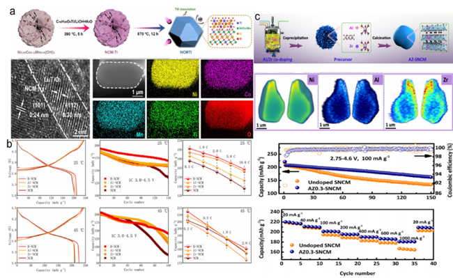
图9 (a)表面Li2TiO3包覆和体相Ti掺杂的双重改性策略示意图以及相应TEM、EDS图[100];(b)H3BO3改性电化学性能示意图[85];(c)Al/Zr原位共掺杂协同效应示意图[101]

Fig. 9 (a) Schematic diagram of the dual modification strategy of surface Li2TiO3 coating and bulk Ti doping[100]. Copyright 2022, Elsevier. (b) Schematic diagram of electrochemical performance of H3BO3 modification[85]. Copyright 2022, Elsevier. (c) Schematic diagram of Al/Zr in situ co-doping synergies[101]. Copyright 2022, Elsevier

6 Conclusions and Prospects

This review summarizes the research progress and existing challenges of single-crystal high-nickel ternary layered cathode materials in recent years, and discusses the performance advantages, synthesis methods, and modification methods of single-crystal high-nickel ternary materials. Single-crystal material particles exist independently, fundamentally avoiding the generation of intergranular microcracks, preventing the electrolyte from penetrating along the grain boundaries, and exhibiting excellent crack resistance under high pressure. Therefore, failure mechanisms occurring on the surface, such as CEI formation, transition metal dissolution, and surface reconstruction, are all alleviated.
From the perspective of synthesis, the multi-step calcination method is adopted, and increasing the calcination temperature accelerates the grain growth rate, which is more conducive to synthesizing the target single crystal. However, excessively high temperatures can also lead to agglomeration and cation mixing. At the same time, high temperatures will also increase the volatilization of lithium salts, so it is necessary to add an appropriate amount of additional lithium salt to offset this volatilization. In addition, the precursor before calcination of the single crystal material is also one of the important factors affecting the synthesis of single crystals. The preparation of the precursor requires controlling the relevant reaction conditions to synthesize precursor particles with a suitable particle size, making it easier to obtain single crystal materials with a suitable particle size after subsequent calcination.
From the perspective of modification, element doping enhances structural stability and improves cycling performance; surface coating effectively prevents the material surface from contacting the electrolyte, thereby reducing the occurrence of side reactions. However, a single modification strategy cannot simultaneously improve battery cycling stability, energy density, and rate performance. The synergistic effects of dual or even multiple modification strategies should attract increasing attention from researchers.
Overall, single-crystal high-nickel ternary layered cathode materials have prominent advantages in terms of electrochemistry and safety, with broad commercial application prospects, but there are still some issues to be addressed, such as poor lithium-ion diffusion kinetics, which requires more research to elucidate the mechanism and corresponding solutions. In the future, the characteristics of various modification strategies should be combined to maximize the advantages of single-crystal high-nickel ternary layered cathode materials.
On the other hand, all-solid-state lithium-ion batteries (ASSLB) represent a new direction for the future development of lithium-ion batteries. However, the current issue of polycrystalline cathode material particle fracture significantly restricts the progress of ASSLB. At present, the key to ASSLB development lies in enhancing the ionic conductivity and interfacial stability of solid electrolytes (SEs). Cathode materials in single-crystal form can reduce the tendency to develop intergranular microcracks during cycling, allowing the cathode materials and SEs to maintain proper contact, thereby improving the diffusion rate of lithium ions and interfacial stability, and thus enhancing electrochemical performance. Therefore, the development of single-crystal high-nickel ternary layered cathode materials brings great hope for the practical application of ASSLB.
[1]
Myung S T, Maglia F, Park K J, Yoon C S, Lamp P, Kim S J, Sun Y K. ACS Energy Lett., 2017, 2(1): 196.

[2]
Dai L Q, Li N, Chen L, Su Y F, Chen C M, Su F Y, Bao L Y, Chen S, Wu F. Chin. J. Chem., 2021, 39(2): 345.

[3]
Li N, Sallis S, Papp J K, McCloskey B D, Yang W L, Tong W. Nano Energy, 2020, 78: 105365.

[4]
Luo Y H, Wei H X, Tang L B, Huang Y D, Wang Z Y, He Z J, Yan C, Mao J, Dai K H, Zheng J C. Energy Storage Mater., 2022, 50: 274.

[5]
Mu L Q, Kan W H, Kuai C G, Yang Z J, Li L X, Sun C J, Sainio S, Avdeev M, Nordlund D, Lin F. ACS Appl. Mater. Interfaces, 2020, 12(11): 12874.

[6]
Tan X R, Zhang M L, Li J, Zhang D Y, Yan Y X, Li Z M. Ceram. Int., 2020, 46(14): 21888.

[7]
Wu F, Liu N, Chen L, Su Y F, Tan G Q, Bao L Y, Zhang Q Y, Lu Y, Wang J, Chen S, Tan J. Nano Energy, 2019, 59: 50.

[8]
Fan X M, Hu G R, Zhang B, Ou X, Zhang J F, Zhao W G, Jia H P, Zou L F, Li P, Yang Y. Nano Energy, 2020, 70: 104450.

[9]
Peng F, Chu Y Q, Li Y, Pan Q C, Yang G C, Zhang L X, Hu S J, Zheng F H, Wang H Q, Li Q Y. J. Energy Chem., 2022, 71: 434.

[10]
Ran A H, Chen S X, Cheng M, Liang Z, Li B H, Zhou G M, Kang F Y, Zhang X, Wei G D. J. Mater. Chem. A, 2022, 10(37): 19680.

[11]
Mizushima K, Jones P C, Wiseman P J, Goodenough J B. Mater. Res. Bull., 1980, 15(6): 783.

[12]
Manthiram A, Song B H, Li W D. Energy Storage Mater., 2017, 6: 125.

[13]
De Biasi L, Schiele A, Roca-Ayats M, Garcia G, Brezesinski T, Hartmann P, Janek J. ChemSusChem, 2019, 12(10): 2240.

[14]
Li Y J, Zhu X Y, Su Y F, Xu L F, Chen L, Cao D Y, Li N, Wu F. Small, 2024, 20(23): 2307292.

[15]
Xu L F, Chen S, Su Y F, Shen X, He J Z, Avdeev M, Kan W H, Zhang B, Fan W F, Chen L, Cao D Y, Lu Y, Wang L, Wang M, Bao L Y, Zhang L, Li N, Wu F. ACS Appl. Mater. Interfaces, 2023, 15(47): 54559.

[16]
Whittingham M S. Chem. Rev., 2004, 104(10): 4271.

[17]
Ohzuku T, Makimura Y. Chem. Lett., 2001, 30(7): 642.

[18]
Hou P Y, Gong M S, Tian Y H, Li F. J. Colloid Interface Sci., 2024, 653: 129.

[19]
Yin S Y, Deng W T, Chen J, Gao X, Zou G Q, Hou H S, Ji X B. Nano Energy, 2021, 83: 105854.

[20]
Wang L M, Su Q M, Shi W H, Wang C B, Li H, Wang Y T, Du G H, Zhang M, Zhao W Q, Ding S K, Xu B S. Electrochim. Acta, 2022, 435: 141411.

[21]
Bianchini M, Roca-Ayats M, Hartmann P, Brezesinski T, Janek J. Angew. Chem., 2019, 131(31): 10542.

[22]
Li J, Zhong W T, Deng Q, Zhang Q M, Yang C H. Int. J. Extrem. Manuf., 2022, 4(4): 042004.

[23]
Wu F, Li Q, Chen L, Wang Z R, Chen G, Bao L Y, Lu Y, Chen S, Su Y F. Acta Phys. Chim. Sin., 2020, 38(5): 2007017.

[24]
Niu S J, Xu J M, Wu K, Liang C D, Zhu G B, Qu Q T, Zheng H H. Mater. Chem. Phys., 2021, 260: 124046.

[25]
Kim W S, Kim S B, Jang I C, Lim H H, Lee Y S. J. Alloys Compd., 2010, 492(1-2): L87.

[26]
Luo D, Cui J X, Zhang B K, Fan J M, Liu P Z, Ding X K, Xie H X, Zhang Z H, Guo J J, Pan F, Lin Z. Adv. Funct. Mater., 2021, 31(14): 2009310.

[27]
Liu W, Wang M, Gao X L, Zhang W D, Chen J T, Zhou H H, Zhang X X. J. Alloys Compd., 2012, 543: 181.

[28]
Xie Q, Li W D, Manthiram A. Chem. Mater., 2019, 31(3): 938.

[29]
Liu W, Oh P, Liu X E, Lee M J, Cho W, Chae S, Kim Y, Cho J. Angew. Chem. Int. Ed., 2015, 54(15): 4440.

[30]
Ni L S, Guo R T, Deng W T, Wang B W, Chen J, Mei Y, Gao J Q, Gao X, Yin S Y, Liu H Q, Zhang S, Zou G Q, Hou H S, Ji X B. Chem. Eng. J., 2022, 431: 133731.

[31]
Qian G N, Zhang Y T, Li L S, Zhang R X, Xu J M, Cheng Z J, Xie S J, Wang H, Rao Q L, He Y S, Shen Y B, Chen L W, Tang M, Ma Z F. Energy Storage Mater., 2020, 27: 140.

[32]
Deng X M, Zhang R, Zhou K, Gao Z Y, He W, Zhang L H, Han C P, Kang F Y, Li B H. Energy Environ. Mater., 2023, 6(3): e12331.

[33]
Abdollahifar M, Cavers H, Scheffler S, Diener A, Lippke M, Kwade A. Adv. Energy Mater., 2023, 13(40): 2300973.

[34]
Han X Y, Meng Q F, Sun T L, Sun J T. J. Power Sources. 2010, 195(10): 3047.

[35]
Kim Y. ACS Appl. Mater. Interfaces, 2012, 4(5): 2329.

[36]
Fu F, Xu G L, Wang Q, Deng Y P, Li X, Li J T, Huang L, Sun S G. J. Mater. Chem. A, 2013, 1(12): 3860.

[37]
Li J, Cameron A R, Li H Y, Glazier S, Xiong D J, Chatzidakis M, Allen J, Botton G A, Dahn J R. J. Electrochem. Soc., 2017, 164(7): A1534.

[38]
Wang L, Wu B R, Mu D B, Liu X J, Peng Y Y, Xu H L, Liu Q, Gai L, Wu F. J. Alloys Compd., 2016, 674: 360.

[39]
Cho W, Lim Y J, Lee S M, Kim J H, Song J H, Yu J S, Kim Y J, Park M S. ACS Appl. Mater. Interfaces, 2018, 10(45): 38915.

[40]
Xu X, Huo H, Jian J Y, Wang L G, Zhu H, Xu S, He X S, Yin G P, Du C Y, Sun X L. Adv. Energy Mater., 2019, 9(15): 1970051.

[41]
Bi Y J, Tao J H, Wu Y Q, Li L Z, Xu Y B, Hu E Y, Wu B B, Hu J T, Wang C M, Zhang J G, Qi Y, Xiao J. Science, 2020, 370(6522): 1313.

[42]
Wang J P, Lu X B, Zhang Y C, Zhou J H, Wang J X, Xu S M. J. Energy Chem., 2022, 65: 681.

[43]
Zhang Z, Hong B, Yi M Y, Fan X M, Zhang Z A, Huang X B, Lai Y Q. Chem. Eng. J., 2022, 445: 136825.

[44]
Nam G, Hwang J, Kang D H, Oh S, Chae S, Yoon M, Ko M. J. Energy Chem., 2023, 79: 562.

[45]
Croy J R, Balasubramanian M, Gallagher K G, Burrell A K. Acc. Chem. Res., 2015, 48(11): 2813.

[46]
Wu F, Liu N, Chen L, Li N, Dong J Y, Lu Y, Tan G Q, Xu M Z, Cao D Y, Liu Y F, Chen Y B, Su Y F. J. Energy Chem., 2021, 62: 351.

[47]
Liu Y L, Harlow J, Dahn J. J. Electrochem. Soc., 2020, 167(2): 020512.

[48]
Logan E R, Hebecker H, Ma X W, Quinn J, HyeJeong Y, Kumakura S, Paulsen J, Dahn J R. J. Electrochem. Soc., 2020, 167(6): 060530.

[49]
Duan J G, Wu C, Cao Y B, Huang D H, Du K, Peng Z D, Hu G R. J. Alloys Compd., 2017, 695: 91.

[50]
Yang X R, Chen J W, Zheng Q F, Tu W Q, Xing L D, Liao Y H, Xu M Q, Huang Q M, Cao G Z, Li W S. J. Mater. Chem. A. 2018, 6(33): 16149.

[51]
Li N, Sallis S, Papp J K, Wei J, McCloskey B D, Yang W L, Tong W. ACS Energy Lett., 2019, 4(12): 2836.

[52]
Su Y F, Zhang Q Y, Chen L, Bao L Y, Lu Y, Chen S, Wu F. J. Energy Chem., 2022, 65: 236.

[53]
Su Y F, Wang M, Zhang M X, Chen L, Li N, Chen L, Chen Y B, Liu J Y, Li Y L. J. Alloys Compd., 2022, 905: 164204.

[54]
Wei W F, Ding Z P, Chen C, Yang C, Han B, Xiao L, Liang C P, Gao P, Cho K. Acta Mater., 2021, 212: 116914.

[55]
Kong X B, Zhang Y G, Peng S Y, Zeng J, Zhao J B. ACS Sustainable Chem. Eng., 2020, 8(39): 14938.

[56]
Tan Z L, Li Y J, Xi X M, Jiang S J, Li X H, Shen X J, He Z J. ACS Appl. Mater. Interfaces, 2023, 15(6): 8555.

[57]
Sun J M, Cao D X, Yang D H, He P P, Dato M A, Cabana P J, Zhou P H. Angew. Chem. Int. Ed., 2022, 61(40): e202207225.

[58]
Li F, Kong L L, Sun Y Y, Jin Y C, Hou P Y. J. Mater. Chem. A. 2018, 6(26): 12344.

[59]
Wu N T, Wu H, Kim J K, Liu X M, Zhang Y. ChemElectroChem, 2018, 5(1): 78.

[60]
Hu D Z, Su Y F, Chen L, Li N, Bao L Y, Lu Y, Zhang Q Y, Wang J, Chen S, Wu F. J. Energy Chem., 2021, 58: 1.

[61]
Zhu H, Tang Y, Wiaderek K M, Borkiewicz O J, Ren Y, Zhang J, Ren J C, Fan L L, Li C C, Li D F, Wang X L, Liu Q. Nano Lett., 2021, 21(23): 9997.

[62]
Liao Q T, Guo S J, Qi M Y, Zhang S D, Ma P Z, Li J Y, Cao A M, Wan L J. Sustain. Energy Fuels, 2023, 7(19): 4805.

[63]
Luo B, Li H, Qi H Y, Liu Y, Zheng C B, Du W T, Zhang J F, Chen L. J. Energy Chem., 2024, 88: 327.

[64]
You B Z, Wang Z X, Shen F, Chang Y J, Peng W J, Li X H, Guo H J, Hu Q Y, Deng C W, Yang S, Yan G C, Wang J X. Small Meth., 2021, 5(8): 2100234.

[65]
Su Y F, Li L W, Chen G, Chen L, Li N, Lu Y, Bao L Y, Chen S, Wu F. Chin. J. Chem., 2021, 39(1): 189.

[66]
Hu D Z, Zhang Q Y, Tian J, Chen L, Li N, Su Y F, Bao L Y, Lu Y, Cao D Y, Yan K, Chen S, Wu F. ACS Appl. Mater. Interfaces, 2021, 13(5): 6286.

[67]
Jiang W, Fan X M, Zhu X X, Wu Z Z, Li Z H, Huang R Z, Zhao S, Zeng X M, Hu G R, Zhang B, Zhang S Q, Zhu L Y, Yan L J, Ling M, Wang L G, Liang C D. J. Power Sources. 2021, 508: 230335.

[68]
Lu H Q, Wu F, Su Y F, Li N, Chen S, Bao L Y. Acta Phys. Chim. Sin., 2010, 26(1): 51.

[69]
Liu X S, Shi J W, Zheng B Z, Chen Z R, Su Y, Zhang M J, Xie C P, Su M T, Yang Y. ACS Appl. Mater. Interfaces, 2021, 13(35): 41669.

[70]
Langdon J, Manthiram A. Energy Storage Mater., 2021, 37: 143.

[71]
Li J, Li H Y, Stone W, Weber R, Hy S, Dahn J R. J. Electrochem. Soc., 2017, 164(14): A3529.

[72]
Zhu Y Z, Wang K, Zheng S S, Wang H J, Dong J C, Li J F. Acta Phys. Chim. Sin., 2023: 2304040.

[73]
Zhang X, Hu G R, Peng Z D, Cao Y B, Li L Y, Tan C P, Wang Y Z, Wang W G, Du K. Ceram. Int., 2021, 47(18): 25680.

[74]
Guo F Y, Xie Y F, Zhang Y X. Nano Res., 2022, 15(3): 2052.

[75]
Li H Y, Li J, Zaker N, Zhang N, Botton G A, Dahn J R. J. Electrochem. Soc., 2019, 166(10): A1956.

[76]
Ryu H H, Namkoong B, Kim J H, Belharouak I, Yoon C S, Sun Y K. ACS Energy Lett., 2021, 6(8): 2726.

[77]
Yang J C, Xu S Y, Yu J, Li Y J, He Z J, Wu F X, Zhang T, Hao S P, Jiang S J, Pan J W, Xi X M, Liu S W. Chem. Commun., 2023, 59(66): 9980.

[78]
Meng X H, Lin T, Mao H C, Shi J L, Sheng H, Zou Y G, Fan M, Jiang K C, Xiao R J, Xiao D D, Gu L, Wan L J, Guo Y G. J. Am. Chem. Soc., 2022, 144(25): 11338.

[79]
Yan P F, Zheng J M, Gu M, Xiao J, Zhang J G, Wang C M. Nat. Commun., 2017, 8: 14101.

[80]
Liu Y, Fan X M, Luo B, Zhao Z W, Shen J X, Liu Z H, Xiao Z M, Zhang B, Zhang J F, Ming L, Ou X. J. Colloid Interface Sci., 2021, 604: 776.

[81]
Zhang Y D, Liu J D, Xu W C, Lu Y, Ma H, Cheng F Y, Chen J. J. Power Sources. 2022, 535: 231445.

[82]
Zou Y G, Mao H C, Meng X H, Du Y H, Sheng H, Yu X Q, Shi J L, Guo Y G. Angew. Chem., 2021, 133(51): 26739.

[83]
Zhang D K, Liu Y, Feng L W, Qin W C. J. Solid State Chem., 2022, 306: 122796.

[84]
Kong X B, Yang H Y, Zhang Y G, Dai P P, Tang Y L, Zeng J, Zhao J B. Chem. Eng. J., 2023, 452: 139431.

[85]
Li M H, Cheng L, Zhang B, Deng P, Xiao Z M, Ming L, Zhao Y, Xu B H, Ou X. J. Alloys Compd., 2022, 907: 164489.

[86]
Zhang B, Cheng L, Deng P, Xiao Z M, Ming L, Zhao Y, Xu B H, Zhang J F, Wu B, Ou X. J. Alloys Compd., 2021, 872: 159619.

[87]
Feng Z, Zhang S, Rajagopalan R, Huang X B, Ren Y R, Sun D, Wang H Y, Tang Y G. ACS Appl. Mater. Interfaces, 2021, 13(36): 43039.

[88]
Wu F, Liu N, Chen L, Li N, Lu Y, Cao D Y, Xu M Z, Wang Z R, Su Y F. ACS Appl. Mater. Interfaces, 2021, 13(21): 24925.

[89]
Wu F, Wang M, Su Y F, Chen S, Xu B. J. Power Sources. 2009, 191(2): 628.

[90]
Su Y F, Chen G, Chen L, Li Q, Lu Y, Bao L Y, Li N, Chen S, Wu F. Chin. J. Chem., 2020, 38(12): 1817.

[91]
Su Y F, Zhang Q Y, Chen L, Bao L Y, Lu Y, Chen S, Wu F. Acta Phys. Chim. Sin., 2021, 31(3): 2005062.

[92]
Ando K, Yamada Y, Nishikawa K, Matsuda T, Imamura D, Kanamura K. ACS Appl. Energy Mater., 2018, 1(9): 4536.

[93]
Peng F, Zhang L X, Yang G C, Li Y H, Pan Q C, Li Y, Hu S J, Zheng F H, Wang H Q, Li Q Y. Chem. Eng. J., 2023, 451: 138911.

[94]
You L Z, Wen Y, Li G X, Chu B B, Wu J H, Huang T, Yu A S. J. Mater. Chem. A. 2022, 10(10): 5631.

[95]
Sahni K, Ashuri M, He Q R, Sahore R, Bloom I D, Liu Y Z, Kaduk J A, Shaw L L. Electrochim. Acta, 2019, 301: 8.

[96]
Xiong X H, Wang Z X, Yin X, Guo H J, Li X H. Mater. Lett., 2013, 110: 4.

[97]
Su Y F, Chen G, Chen L, Shi Q, Lv Z, Lu Y, Bao L Y, Li N, Chen S, Wu F. ChemSusChem, 2021, 14(8): 1955.

[98]
Li J, Zhong W T, Deng Q, Zhang Q M, Lin Z, Yang C H. Adv. Funct. Mater., 2023, 33(24): 2300127.

[99]
Tang L B, Liu Y, Wei H X, Yan C, He Z J, Li Y J, Zheng J C. J. Energy Chem., 2021, 55: 114.

[100]
Yang Z F, Chen L, Zhu H W, Zhu Y H, Jiang H, Li C Z. J. Mater. Sci. Technol., 2022, 125: 192.

[101]
Ou X, Liu T C, Zhong W T, Fan X M, Guo X Y, Huang X J, Cao L, Hu J H, Zhang B, Chu Y S, Hu G R, Lin Z, Dahbi M, Alami J, Amine K, Yang C H, Lu J. Nat. Commun., 2022, 13: 2319.

Outlines

/