
Progress in the Applications of Polymer-Decorated Black Phosphorus and Black Phosphorus Analog Nanomaterials in Biomedicine
Received date: 2024-05-08
Revised date: 2024-09-09
Online published: 2025-02-07
Supported by
National Natural Science Foundation of China(22072127)
National Natural Science Foundation of China(22372143)
Hebei Natural Science Foundation(C2018203374)
Hebei Natural Science Foundation(B2021203016)
Hebei Natural Science Foundation(B2023203018)
In the realm of two-dimensional nanomaterials, black phosphorus (BP) is considered a promising candidate to address the shortcomings of graphene and transition metal dichalcogenides (TMDs). Low- dimensional black phosphorus (BP) refers to a class of nanomaterials derived from the layered semiconductor BP. These materials exhibit high structural anisotropy, tunable bandgap widths, and high hole and electron mobility, endowing BP with unique properties such as conductivity, photothermal, photodynamic, and mechanical behaviors. BP's near-infrared light response significantly enhances its effectiveness in photothermal and photodynamic antibacterial applications. Additionally, due to its unique layered structure, BP nanosheets (BPNS) possess a high surface-to-volume ratio, making them excellent carriers for loading and delivering other antimicrobial nanomaterials or drugs. First, this article discusses the physical properties of low-dimensional BP and introduces various preparation methods. Furthermore, it systematically reviews exciting therapeutic applications of polymer-modified black phosphorus nanomaterials in various fields, such as cancer treatment (phototherapy, drug delivery, and synergistic immunotherapy), bone regeneration, and neurogenesis. Finally, the paper discusses some challenges facing future clinical trials and potential directions for further research.
1 Introduction
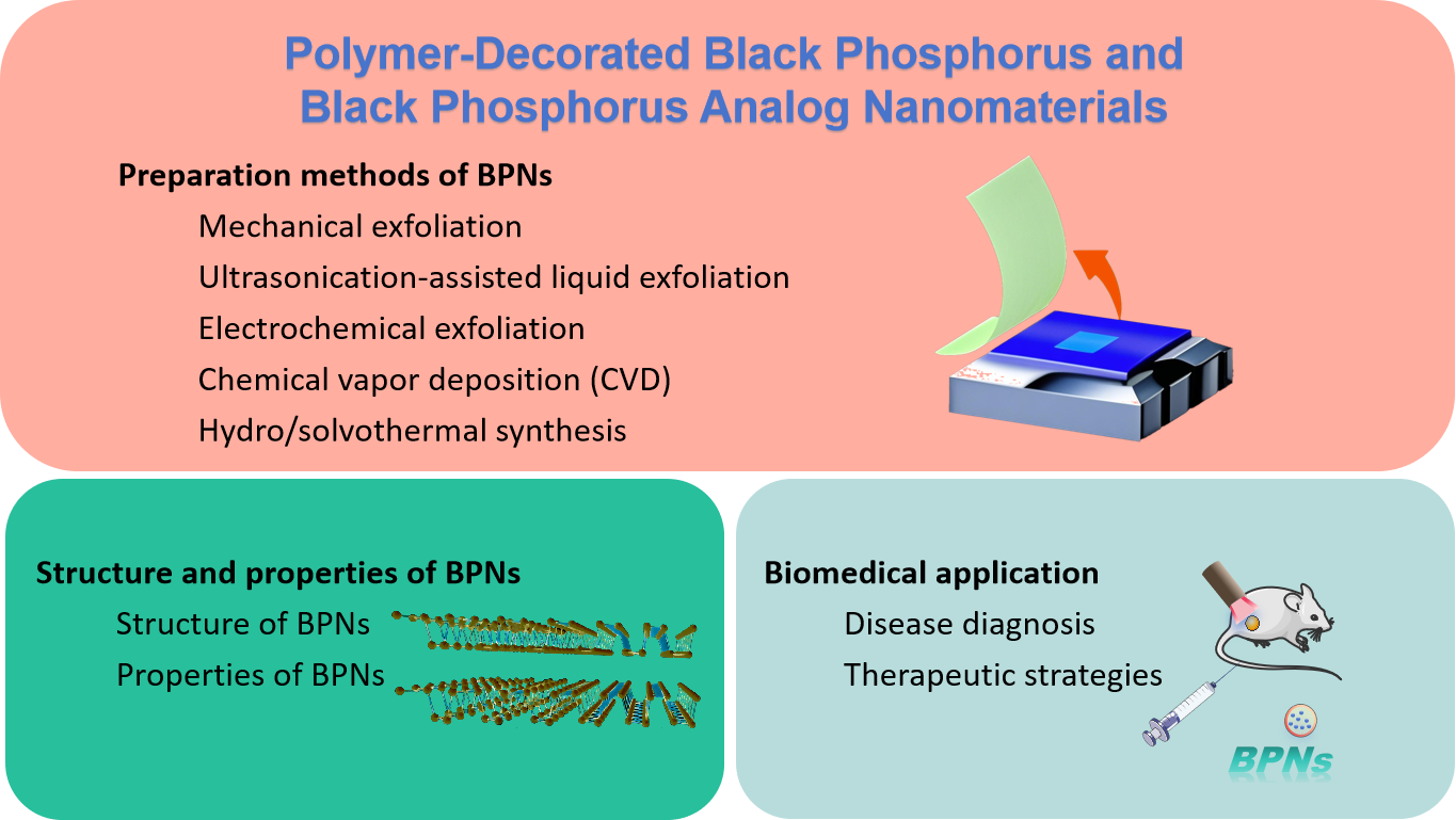
2 Preparation methods of BPNs
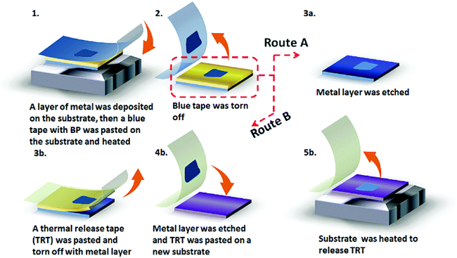
2.1 Mechanical exfoliation
2.2 Ultrasonication-assisted liquid exfoliation
2.3 Electrochemical exfoliation
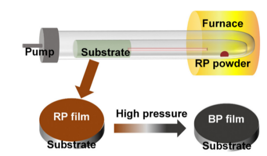
2.4 Chemical vapor deposition (CVD)
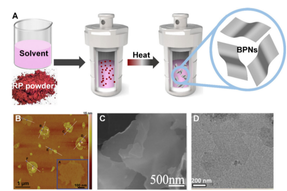
2.5 Hydro/solvothermal synthesis
3 Structure and properties of BPNs
3.1 Structure of BPNs
3.2 Properties of BPNs
4 Biomedical application
4.1 Disease diagnosis
4.2 Therapeutic strategies
5 Conclusion and outlook
Aoqi Su , Xinyu Li , Ran Wang , Lili Gao , Tifeng Jiao . Progress in the Applications of Polymer-Decorated Black Phosphorus and Black Phosphorus Analog Nanomaterials in Biomedicine[J]. Progress in Chemistry, 2025 , 37(2) : 133 -156 . DOI: 10.7536/PC240417
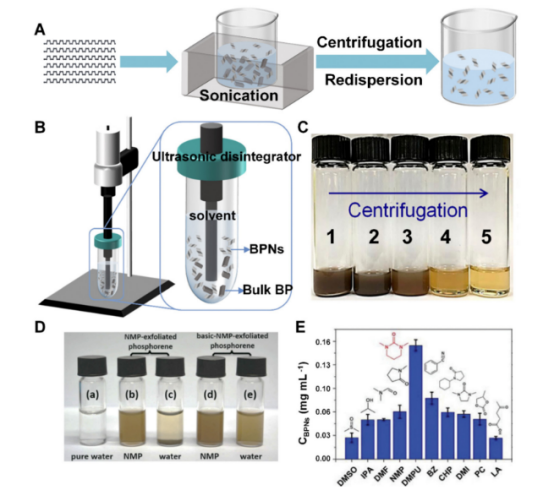
图2 超声波辅助液相剥离BPNs的研究:(A)常规超声波清洗槽的BPNs的剥离过程[7];(B)超声波粉碎机的BPNs的剥离过程[7]; (C) 以不同速度离心后获得的NMP中BPNs混悬液的照片[7] (1)制备时;(2)500 r/min;(3)5000 r/min;(4)10 000 r/min;(5)15 000 r/min);(D)不同溶液中剥离的BPNs的照片;(E)在不同溶剂中超声处理BP(1 mg/mL)3 h,然后以3000 r/min离心30 min后,剥离的BPNs的 浓度[11]Fig. 2 Ultrasonication-assisted liquid exfoliation of BPNs:(A) Exfoliation process of BPNs using conventional ultrasonic cleaning bath[7], (B) Exfoliation process of BPNs using ultrasonic disintegrator[7], (C) Photograph of the BPN suspension in NMP obtained after centrifugation at different speeds ((1) As prepared; (2) 500 r/min; (3) 5000 r/min; (4) 10 000 r/min; (5) 15 000 r/min)[7], (D) Photos of stripped BPNs in different solutions, (E) Concentration of exfoliated BPNs after ultrasonication of BP (1 mg/mL) in different solvents for 3 h followed by centrifugation at 3000 r/min for 30 min[11] |
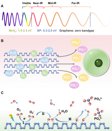
图6 (A)典型二维材料的电磁波谱和带隙范围[34]; (B)BPNs在降解过程中释放出对细胞无毒的PO43-和PO33-[43];(C) BPNs的光诱导环境降解过程[46]Fig. 6 (A) Electromagnetic wave spectrum and bandgap ranges of typical 2D materials[34];(B) BPNs release PO43-and PO33-during degradation, which are non-toxic toward cells[43];(C) The light-induced ambient degradation process of BPNs[46] |
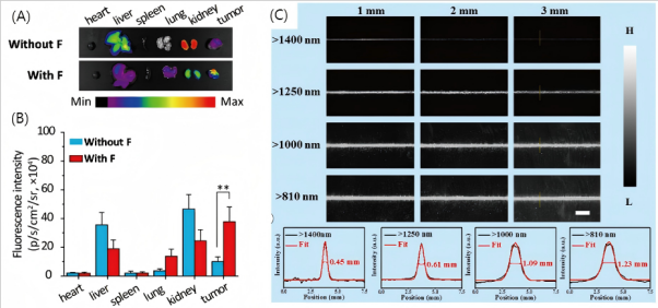
图7 (A)Cy5.5-标记的BP在没有FA和具有FA的情况下在心脏、肝脏、脾脏、肺和肾脏中的离体生物分布;(B)相应的荧光强度;(C)填充有BP@lipid-PEG纳米球水溶液并覆盖有不同厚度的鸡胸切片的毛细管的光致发光图像,由不同波长的光学滤波器捕获。沿沿着黄色虚线的横截面荧光信号强度曲线显示在顶部。比例尺:5 mm[75]Fig. 7 (A) Ex vivo biodistributions of Cy5.5-labeled BP without FA and with FA in heart, liver, spleen, lung, and kidney; (B) corresponding fluorescence intensities; (C) Photoluminescence images of a capillary filled with BP@lipid-PEG nanosphere aqueous solution and covered with the chicken breast slice with different thicknesses, captured by different wavelength optical filters. Cross-sectional fluorescence signal intensity profiles along yellow dotted lines are shown at the top. Scale bar: 5 mm[75] |
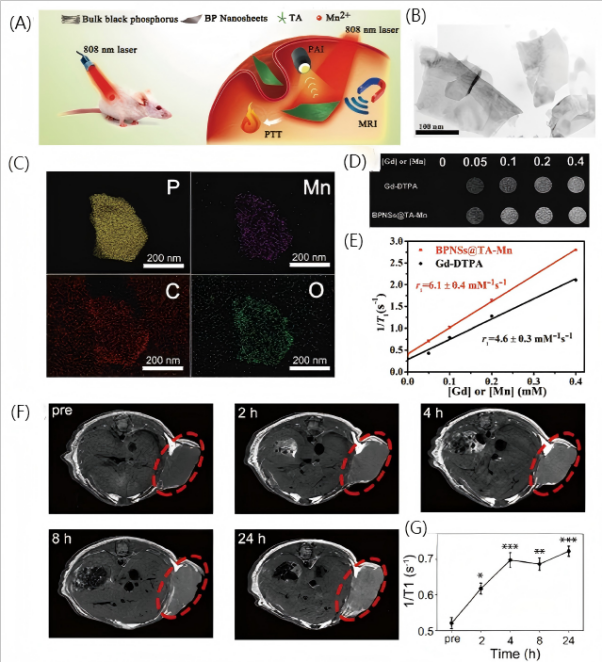
图8 (A)使用BPNS@TA-Mn的MRI/PA双模式成像引导PTT的应用示意图;(B)TEM图像;(C)EDX映射图像;(D)BPNS@TA-Mn与不同金属浓度的Gd-DTPA的T1加权体模图像比较;(E)纵向弛豫率的线性拟合;(F)BPN/MnO2/ DOX注射后荷瘤小鼠体内MRI;(G)相应的时间依赖性T1值变化[96]Fig. 8 (A) Schematic for the application of MRI/PA dual-modal imaging-guided PTT using BPNS@TA-Mn; (B) TEM image; (C) EDX mapping image; (D) T1-Weighted phantom images of BPNS@TA-Mn compared to Gd-DTPA with different metal concentrations; (E) The linear fitting of longitudinal relaxation rates; (F) In vivo MRI of mice bearing HeLa tumor after the injection ofBPN/MnO2/DOX; (G) corresponding time-dependent T1 value changes[96] |
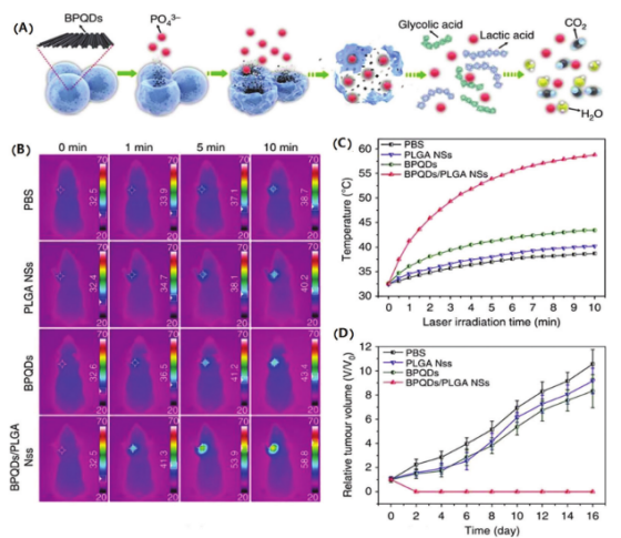
图9 (A)BPQDs/PLGA NSs的制备和降解过程;(B)荷瘤小鼠近红外线照射后的红外热像图;(C)温度变化曲线;(D)BPQDs/PLGA NSs + NIR治疗后的肿瘤体积变化[109]Fig. 9 (A) Preparation and degradation processes of BPQDs/PLGA NSs; (B) Infrared thermographic image; (C) temperature variation curve in tumorbearing mice after NIR irradiation; (D) Tumor volume changes after BPQDs/PLGA NSs + NIR treatment[109] |
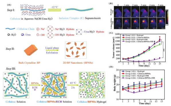
图10 (A) 纤维素/BPNSs水凝胶的合成;(B)不同给药组的体温变化;(C)不同组别治疗后肿瘤体积随时间的变化;(D)四组小鼠体重的变化[110]Fig. 10 (A) Synthesis of cellulose/BPNSs hydrogels; (B) Temperature changes in different treatment groups; (C) Time-dependent tumor volume changes after treatment with different groups; (D) Changes in mouse weights for the four groups[110] |
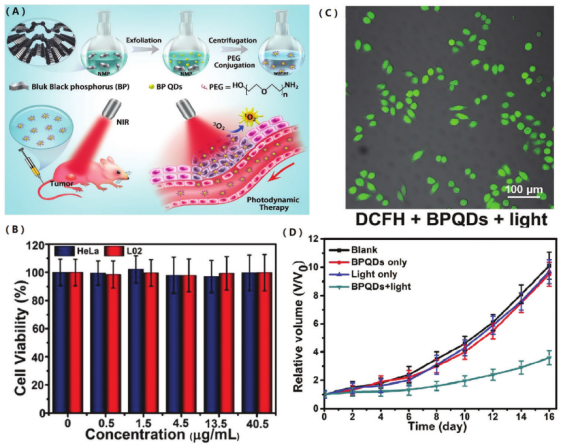
图11 (A)PEG化BPQDs在PDT中的潜在应用的介绍[112];(B)用PEG化BPQDs孵育后HeLa和L02细胞的浓度和细胞活力依赖性;(C)用DCFH-DA + PEG化BPQDs+光照射孵育的HeLa细胞的荧光显微镜图像;(D)不同处理后的肿瘤生长曲线Fig. 11 (A) Introduction of potential applications of PEGylated BPQDs in PDT[112]; (B) Concentrations and cell viability dependence of HeLa and L02 cells after incubation with PEGylated BPQDs; (C) Fluorescence microscope images of HeLa cells incubated with DCFH-DA + PEGylated BPQDs + light irradiation; (D) Tumor growth curves after different treatments |
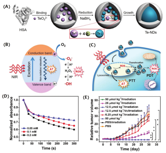
图12 (A)双功能Te NDs的制备;(B)近红外诱导Te NDs产生ROS的机制;(C)细胞内协同处理的示意图;(D)Te NDs的曲线可以产生活性氧;(E)不同治疗组小鼠的肿瘤体积变化[115]Fig. 12 (A) Preparation of bifunctional Te NDs; (B) NIR-induced mechanism of Te NDs for ROS generation; (C) Schematic of intracellular synergistic treatments; (D) Curve of Te NDs can generate ROS; (E) Tumor volume changes in mice for different treatment groups[115] |
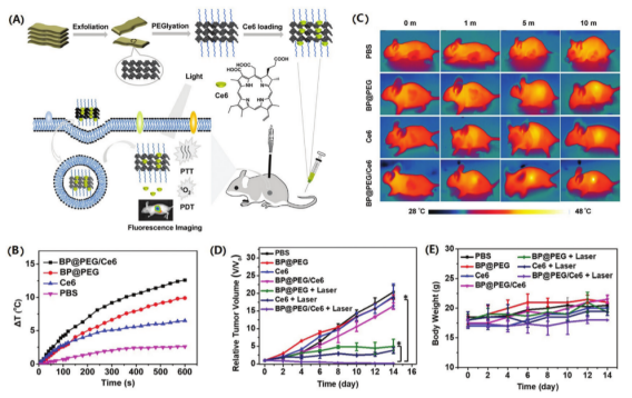
图13 (A)用于癌症治疗的BPNSs@PEG/Ce6 NS制备和PDT/PTT的总结;(B)不同溶液组的温度变化;(C)不同组的体内光热效应;(D)不同组的体内抗肿瘤作用;(E)不同处理组的小鼠体重变化[116]Fig. 13 (A) Summary of BPNSs@PEG/Ce6 NS preparation and PDT/PTT for cancer therapy; (B) Changes in the temperature for the different solution groups; (C) In vivo photothermal effect for the different groups; (D) In vivo antitumor effect for the different groups; (E) Changes in mice weights for the different treatment groups[116] |
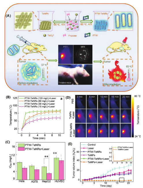
图14 (A)Te NPs和PTW-Te NRs的制备和协同癌症治疗过程;(B)NIR照射下PTW-Te NPs溶液的温度;(C)不同细胞的IC50值;(D)不同治疗组肿瘤内注射的肿瘤部位的IR图;(E)不同治疗组的肿瘤体积[119]Fig. 14 (A) Preparation and synergistic cancer therapy process of Te NPs and PTW-Te NRs; (B) Temperature of PTW-Te NPs solution under NIR irradiation; (C) IC50 values of different cells; (D) IR maps of tumor sites with intratumoral injections for different treatment groups; (E) Tumor volumes for the different treatment groups[119] |
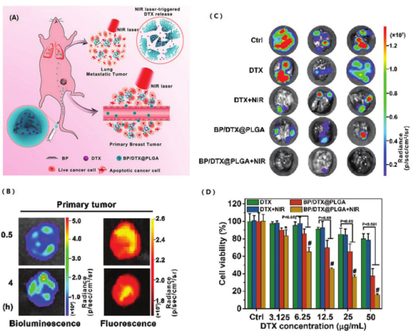
图17 (A)BP/DTX@PLGA NSs的制备和治疗过程的示意图;(B)和(C)注射BP/DTX@PLGA NSs后原发性肿瘤和肺转移性肿瘤的检测;(D)不同处理组的4T1-LG12细胞的细胞活力[131]Fig. 17 (A) Schematic of the preparation and therapeutic processes of BP/DTX@PLGA NSs; (B) and (C) Detection of primary tumors and lung metastatic tumors after BP/DTX@PLGA NSs injection; (D) Cell viabilities of 4T1-LG12 cells for the different treatment groups[131] |
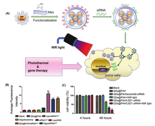
图18 (A)制备新的功能性BPQDs@基于PAH的siRNA递送系统的示意图;(B)不同处理组PA-1细胞转染效率的流式细胞术评价;(C)不同处理组的PA-1细胞的相对细胞活力[133]Fig. 18 (A) Schematic of the preparation of novel, functional BPQDs@PAH-based siRNA delivery systems; (B) Flow cytometry evaluations regarding the transfection efficiencies of PA-1 cells for the different treatment groups; (C) Relative cell viabilities of PA-1 cells for the different treatment groups[133] |
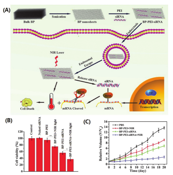
图19 (A)BPNSs-PEI-siRNA和协同PTT和基因疗法的制备过程的示意图;(B)用不同组处理后的细胞活力测定;(C)不同处理组的肿瘤生长曲线[134]Fig. 19 (A) Schematic of the preparation process of BPNSs-PEI-siRNA and synergistic PTT and gene therapy; (B) Cell viability assay after treating with different groups; (C) Curves of tumor growth for the different treatment groups[134] |
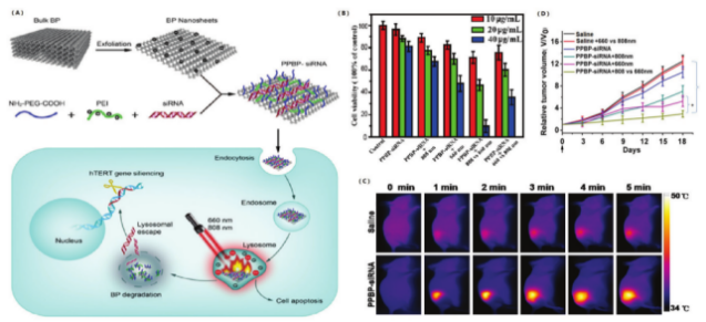
图20 (A)基于PPBP的平台的制备和siRNA递送的示意图;(B)不同处理组的HeLa细胞活力;(C)具有HeLa肿瘤的异种移植小鼠的热图像;(D)不同处理组的皮下HeLa异种移植物的肿瘤生长曲线[135]Fig. 20 (A) Schematic of the preparation and siRNA delivery of a PPBP-based platform; (B) HeLa cell viabilities for the different treatment groups; (C) Thermal images of xenograft mice with HeLa tumor; (D) Tumor growth curves of subcutaneous HeLa xenograft for the different treatment groups[135] |
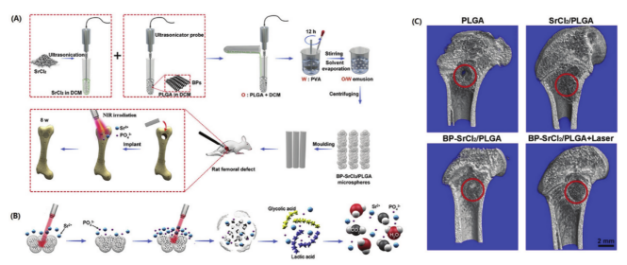
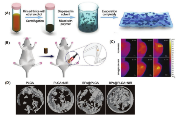
图22 (A)BP-SrCl2/PLGA制备和NIR光触发的骨再生的示意图;(B)BP-SrCl2/ PLGA的释放和降解过程;(C)BP-SrCl2/PLGA植入8周后骨再生的显微CT分析[140]Fig. 22 (A) Schematic of BP-SrCl2/PLGA preparation and NIR-light-triggered bone regeneration; (B) Release and degradation processes of BP-SrCl2/ PLGA; (C) Micro-CT analysis of bone regeneration following BP-SrCl2/PLGA implantation after 8 weeks[140] |
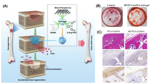
图23 (A)捕获Ca2+以加速生物矿化和骨再生的BPNSs/水凝胶的构建;(B)用BP/PEA/GelMA水凝胶培养的hDPSCs的体外成骨分化的茜素红S染色图像;(C)颅骨模型中骨缺损的修复,植入12周后进行组织切片的H&E染色、碱性磷酸酶染色和免疫组织化学分析(BMP-2)[141]Fig. 23 (A) Construction of BPNSs/hydrogels capturing Ca2+ to accelerate biomineralization and bone regeneration; (B) Alizarin Red S staining images of the in vitro osteogenic differentiation of hDPSCs cultured with a BP/PEA/GelMA hydrogel; (C) Bone defect repair in the calvarial model. H&E staining, alkaline phosphatase staining and immunohistochemical analysis (BMP-2) of the histological sections were performed 12 weeks after implantation[141] |
图24 (A)BPNSs/PLGA膜的制备过程;(B)用BPNSs/PLGA植入的大鼠胫骨的NIR刺激,示出注入和随后的NIR照射的进展的示意图;(C)近红外线照射下大鼠胫骨不同弯曲度的热像;(D)不同治疗组骨再生的MicroCT 3D重建[142]Fig. 24 (A) Preparation process of BPNSs/PLGA membranes; (B) NIR stimulation of rat tibia with BPNSs/PLGA implantation. Schematic diagram showing the progress of implantation and subsequent NIR irradiation; (C) Thermal images of rat tibia with different implantations under NIR irradiation; (D) MicroCT 3D reconstruction of bone regeneration for the different treatment groups[142] |
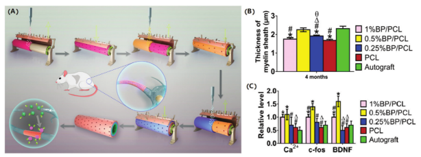
图25 (A)用于神经发生的BP/PCL纳米支架的示意图;(B)基于BP的纳米支架的特性促进坐骨神经的体内再生;(C)BP/PCL纳米支架钙信号通路的研究[154]Fig. 25 (A) Schematics of BP/PCL nanoscaffold for neurogenesis; (B) Properties of BP-based nanoscaffolds promote the in vivo regeneration of sciatic nerves; (C) Investigation of the calcium signaling pathway of BP/PCL-based nanoscaffolds[154] |
| [1] |
|
| [2] |
|
| [3] |
|
| [4] |
|
| [5] |
|
| [6] |
|
| [7] |
|
| [8] |
|
| [9] |
|
| [10] |
|
| [11] |
|
| [12] |
|
| [13] |
|
| [14] |
|
| [15] |
|
| [16] |
|
| [17] |
|
| [18] |
|
| [19] |
|
| [20] |
|
| [21] |
|
| [22] |
|
| [23] |
|
| [24] |
|
| [25] |
|
| [26] |
|
| [27] |
|
| [28] |
|
| [29] |
|
| [30] |
|
| [31] |
|
| [32] |
|
| [33] |
|
| [34] |
|
| [35] |
|
| [36] |
|
| [37] |
|
| [38] |
|
| [39] |
|
| [40] |
|
| [41] |
|
| [42] |
|
| [43] |
|
| [44] |
|
| [45] |
|
| [46] |
|
| [47] |
|
| [48] |
|
| [49] |
|
| [50] |
|
| [51] |
|
| [52] |
|
| [53] |
|
| [54] |
|
| [55] |
|
| [56] |
|
| [57] |
|
| [58] |
|
| [59] |
|
| [60] |
|
| [61] |
|
| [62] |
|
| [63] |
|
| [64] |
|
| [65] |
|
| [66] |
|
| [67] |
|
| [68] |
|
| [69] |
|
| [70] |
|
| [71] |
|
| [72] |
|
| [73] |
|
| [74] |
|
| [75] |
|
| [76] |
|
| [77] |
|
| [78] |
|
| [79] |
|
| [80] |
|
| [81] |
|
| [82] |
|
| [83] |
|
| [84] |
|
| [85] |
|
| [86] |
|
| [87] |
|
| [88] |
|
| [89] |
|
| [90] |
|
| [91] |
|
| [92] |
|
| [93] |
|
| [94] |
|
| [95] |
|
| [96] |
|
| [97] |
|
| [98] |
|
| [99] |
|
| [100] |
|
| [101] |
|
| [102] |
|
| [103] |
|
| [104] |
|
| [105] |
|
| [106] |
|
| [107] |
|
| [108] |
|
| [109] |
|
| [110] |
|
| [111] |
|
| [112] |
|
| [113] |
|
| [114] |
|
| [115] |
|
| [116] |
|
| [117] |
|
| [118] |
|
| [119] |
|
| [120] |
|
| [121] |
|
| [122] |
|
| [123] |
|
| [124] |
|
| [125] |
|
| [126] |
|
| [127] |
|
| [128] |
|
| [129] |
|
| [130] |
|
| [131] |
|
| [132] |
|
| [133] |
|
| [134] |
|
| [135] |
|
| [136] |
|
| [137] |
|
| [138] |
|
| [139] |
|
| [140] |
|
| [141] |
|
| [142] |
|
| [143] |
|
| [144] |
|
| [145] |
|
| [146] |
|
| [147] |
|
| [148] |
|
| [149] |
|
| [150] |
|
| [151] |
|
| [152] |
|
| [153] |
|
| [154] |
|
| [155] |
|
| [156] |
|
/
| 〈 |
|
〉 |