Home Journals Progress in Chemistry
Progress in Chemistry

Abbreviation (ISO4): Prog Chem      Editor in chief: Jincai ZHAO

About  /  Aim & scope  /  Editorial board  /  Indexed  /  Contact  / 
Review

Flexible Pressure Sensor Based on Polydimethylsiloxane

  • Guang Yang ,
  • Demei Yu , *
Expand
  • School of Chemistry,Xi'an Jiaotong University,Xi'an 710115,China

Received date: 2024-10-08

  Revised date: 2024-11-19

  Online published: 2025-03-20

Supported by

Shaanxi Provincial Department of Science and Technology,General Project-Youth Project(2022JQ-485)

Abstract

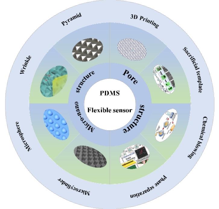
With the advancement of technology,flexible pressure sensors have been widely utilized in wearable device fields such as medical monitoring and motion monitoring,primarily due to their thinness,lightness,flexibility,good ductility,as well as their faster response speed and higher sensitivity compared to traditional rigid sensors. When subjected to external forces,the elastic elements within these sensors undergo deformation,converting mechanical signals into electrical signals. Consequently,the choice of elastic elements significantly impacts the overall performance of flexible pressure sensors. Polydimethylsiloxane (PDMS) is extensively used as a flexible substrate in sensors because of its stable chemical properties,good thermal stability,low preparation cost,and excellent biocompatibility. By collecting relevant information,this paper reviews the sensing mechanisms of PDMS-based flexible pressure sensors,introduces preparation techniques to improve the properties of PDMS materials,including the recently popular methods of introducing porous structures and constructing surface architectures,and discusses the applications of PDMS-based flexible pressure sensors in medical monitoring,electronic skin,and other fields. Finally,the challenges faced by PDMS-based flexible sensors and their future opportunities are prospected.

Contents

1 Introduction

2 Flexible pressure sensor

3 Fabrication technology of flexible sensor with improved performance

3.1 Pore structure

3.2 Surface micro-nano structures

4 Application of flexible pressure sensor based on PDMS

4.1 Health monitoring

4.2 Electronic skin

5 Conclusion and outlook

Cite this article

Guang Yang , Demei Yu . Flexible Pressure Sensor Based on Polydimethylsiloxane[J]. Progress in Chemistry, 2025 , 37(4) : 536 -550 . DOI: 10.7536/PC241001
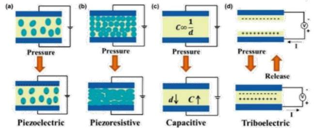
1 Introduction

In the 21st century, significant progress has been made in the research of flexible pressure sensors. Flexible pressure sensors mainly achieve pressure monitoring through the sensing characteristics of elastic materials. According to different sensing mechanisms, they can be categorized into four types: triboelectric, piezoelectric, capacitive, and resistive[1-4]. Their emergence has resolved the mechanical mismatch between traditional rigid components and soft curved systems[5], making wearable applications of real-time monitoring devices possible.
Elastic materials are the most important components in flexible pressure sensors. Selecting appropriate elastic materials as the flexible substrate for pressure sensors not only enables the sensor to undergo wider range of deformation and response when subjected to external forces, but also allows the sensor to better withstand issues such as fatigue wear and aging after experiencing deformations like stretching, compression, and bending[6-7]. Therefore, over the past few decades, extensive research has been conducted on various elastic materials that can serve as flexible substrates for preparing sensors with higher performance[8-9].
The elastic materials currently used include polytetrafluoroethylene[10], modified silicone rubber[11], flexible phenyl silicone[12], polyurethane[13-14], polydimethylsiloxane[15-16], and polyacrylamide[17]. Among them, polydimethylsiloxane (PDMS) is an elastic polymer containing silicon groups, whose molecular backbone structure mainly consists of repeating units [Si(CH3)2O]. Due to its stable chemical properties[18], good thermal stability[19], excellent biocompatibility[20], high flexibility[21], and capability for repeated stretching[22], it has been widely applied in the fabrication of flexible sensors for health monitoring, electronic skins, human-machine interaction, wireless signal transmission, and motion monitoring[23-30].
This paper summarizes the current development status of flexible pressure sensors based on PDMS. Firstly, a comprehensive introduction to currently common flexible pressure sensors and their sensing mechanisms is presented; then, specific methods for improving the sensitivity and expanding the detection range of flexible pressure sensors are described; finally, applications of PDMS-based flexible pressure sensors are listed, and their future development prospects are discussed.

2 Flexible Pressure Sensors

Flexible pressure sensors are typically composed of a flexible substrate, sensing elements, electrodes, and an encapsulation layer. When subjected to external force, the flexible substrate deforms, converting the mechanical signal into an electrical signal, thereby detecting the applied force.
As shown in Fig. 1, according to different sensing principles, flexible pressure sensors can be mainly divided into resistive, capacitive, piezoelectric, and triboelectric types[31]. Among them, resistive and capacitive sensors have already been applied in various fields due to their simple fabrication, while piezoelectric and triboelectric sensors are receiving significant attention because of their certain self-recovery capabilities. Table 1 compares the four different types of flexible sensors, highlighting their respective characteristics in sensing mechanisms, advantages and disadvantages, as well as application scenarios.
图1 柔性压力传感器工作机理示意图(a)压电型;(b)电阻型;(c)电容型;(d)摩擦电型[31]

Fig.1 Schematic diagram of working mechanism of flexible pressure sensor (a) Piezoelectric type;(b) Resistive type;(c) Capacitive type;(d) Triboelectric type[31]

表1 四种不同类型柔性压力传感器的工作原理及其优缺点

Table 1 The working principle,advantages and disadvantages of four different types of flexible pressure sensors

Type Operating principle Conventional materials Advantage Disadvantage
Resistive pressure sensor Changes in resistance caused by changes in external forces (resistance effect) Piezoresistive materials and conductive polymer composites Simple structure
Single signal
Low power consumption
Easy affected by temperature and environment
Capacitive pressure sensor The pressure input is converted to the capacitance change of the parallel plate capacitor Dielectric material Fast response speed
Good stability
High precision
Susceptible to outside interference
Piezoelectric pressure sensor Piezoelectric effect Piezoelectric materials Self-electric
High sensitivity
Easy to generate charge leakage problem
Low output signal
Triboelectric pressure sensor Triboelectric effect and principle of electrostatic induction Flexible polymer materials such as PETPI and PMMA No external power
Easy to integrate
High sensitivity
Limited measuring range
Gong et al.[32] prepared a wearable resistive pressure sensor based on ultra-thin nanowires, with the entire fabrication process shown in Fig. 2. First, nanowires were immersed into thin paper to synthesize AuNW paper, which was then fabricated into a sandwich structure with PDMS. When external force is applied, AuNWs come into contact with the interdigital electrode array, generating more conductive pathways and thus increasing the conducted current. Conversely, the number of AuNWs bridging the finger electrodes decreases, resulting in reduced current. This sensor features low power consumption (<30 μW), fast response time (<17 ms), and high sensitivity (>1.14 kPa-1).
图2 (a)基于AuNWs涂层薄纸的压力传感器的制造示意图;(b)金纳米线涂层组织纤维形态的扫描电子显微镜图像[32]

Fig.2 (a) Schematic diagram for the manufacture of a pressure sensor based on AuNWs coated tissue paper;(b) Scanning electron microscopy (SEM) images of the morphology of tissue fibers coated with gold nanowires [32]

Capacitive flexible sensors more commonly utilize dielectric materials such as PDMS material[33], stretchable silicon nanoribbons[34], and graphene materials[35]. Sarwar et al.[36] developed a capacitive pressure sensor capable of monitoring finger movements based on ionically conductive hydrogel electrodes. The fabrication process and sensing mechanism are illustrated in Fig. 3(a). Initially, PDMS was cured in a grooved mold; subsequently, wire patterns were printed on the PDMS surface. Finally, microchannels were formed on the PDMS surface through plasma bonding. This unique architecture effectively reduced the power consumption of the sensor, resulting in an average power consumption of less than 1 mW, thus significantly conserving public resources. Additionally, to improve the response speed of the sensor, Kim et al.[37] coated a layer of SiO2 nanoparticles onto the PDMS/PEDOT material, fabricating a highly transparent and sensitive capacitive flexible pressure sensor, as shown in Fig. 3(b). The SiO2 nanoparticles dispersed within the PDMS/PEDOT formed a thin film layer and created a capacitive sensor through a stacked configuration. Therefore, adjusting the size of the SiO2 particles can enhance the sensitivity and transparency of the sensor, facilitating additional functionalities for capacitive pressure sensors.
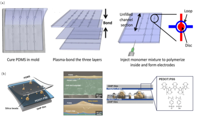
图3 (a)在模具中固化的PDMS以及其在电介质的顶部和底部形成的垂直通道和离子导电电极图像[36];(b)透明电容式压力传感器和传感器层的横截面SEM图像[37]

Fig.3 (a) Images of PDMS solidified in the mold and the vertical channels and ionic conductive electrodes it forms on the top and bottom of the dielectric [36];(b) SEM image of transparent capacitive pressure sensor and cross section of sensor layer image [37]

Compared to the first two types of conventional flexible pressure sensors, piezoelectric sensors have the major advantage of not requiring an external power source during sensing. When subjected to force, a potential difference is generated within the material, enabling self-power generation. This characteristic presents unique advantages in the current era of energy shortages[38]. Due to the tendency of piezoelectric materials to polarize under force, which can lead to uneven electric fields, researchers have increasingly opted for matrix materials to address this issue. Among them, PDMS has become the primary research focus due to its low cost and ease of preparation. Sultana et al.[39] incorporated ZnS-NRs and PANI into PDMS to fabricate a composite film, significantly improving the dielectric properties of the composite material through structural optimization, thereby considerably reducing the breakdown strength, offering new insights into the selection of materials for piezoelectric sensors.
Most of the existing triboelectric pressure sensors utilize the triboelectric nanogenerator (TENG), proposed by Fan et al. in 2012 [40], as an energy source. By leveraging the characteristics of flexible pressure sensors, these devices convert mechanical force signals into electrical signals for measurement and characterization. As an emerging energy harvesting device, TENG can generate a potential difference within the sensor when subjected to external forces, enabling low-power consumption or even self-powered systems, which holds great promise for expanding the application prospects of flexible pressure sensors.

3 Performance Improvement Preparation Process of Flexible Sensors

In the development of flexible pressure sensors based on PDMS materials, various methods have been proposed to improve their overall performance. Currently, two mainstream approaches involve introducing porous structures into PDMS[9] and constructing micro/nanostructures on the surface of PDMS[41].

3.1 Pore Structure

As a type of porous polymer material, porous PDMS has been extensively studied by researchers in terms of its physical structure, preparation processes, and practical applications[42-43]. Introducing a porous structure not only enhances the sensing performance of flexible sensors but also improves their hydrophobic properties, mechanical strength, and thermal stability[44-46], thereby enhancing the overall performance of porous PDMS materials. The existing preparation techniques for porous structures have become relatively mature, and Table 2 lists commonly used methods along with their respective advantages and disadvantages, including 3D printing technology, phase separation technology, template leaching method, and chemical foaming method.
表2 PDMS材料引入孔隙结构的制造技术和其优缺点

Table 2 Manufacturing technology,advantages and disadvantages of PDMS materials introduced into pore structure

Manufacturing method Aperture Advantage Disadvantage
3D Printing Submicron scale Complex structure preparation
Precise control of aperture
High cost
Low efficiency
Phase separation technique Ten-micron scale Easy to prepare
Easy to control aperture
Organic solvents can be harmful
Chemical foaming process Micrometer scale Simple process
Low cost
Aperture control is difficult
Template removal method Hundred-micron scale The aperture size is adjustable
Porosity control
Easy to prepare
The template limits the preparation of the aperture
Aperture distribution is not easy to control

3.1.1 3D Printing Technology

3D printing technology converts digital designs into physical models by layer-by-layer printing, accumulating materials into solid objects. Due to its low material consumption and ability to fabricate complex structures, it has been increasingly applied in the preparation of porous PDMS materials[47]. As shown in Fig. 4(a), Woo et al.[48] determined a method for preparing pore structures on PDMS material surfaces through direct ink printing by investigating the functional relationships between the mechanical properties of porous PDMS materials and the printing and filling processes. This approach eliminates the need for separate etching processes and additional mold fabrication, significantly reducing production costs while achieving highly tunable mechanical properties in the resulting porous PDMS materials. As illustrated in Fig. 4(b) and 4(c), Duan et al.[49] fabricated porous PDMS materials using 3D printing technology and further developed stretchable conductors (OPCG) by integrating them with carbon nanotubes and graphene. They also conducted modeling analyses using finite element methods to study changes in electrical conductivity during stretching, demonstrating its higher conductivity and excellent retention capability. The porous structure fabricated via 3D printing endows S-OPCG with exceptional overall performance, making it highly promising for applications in flexible stretchable sensors.
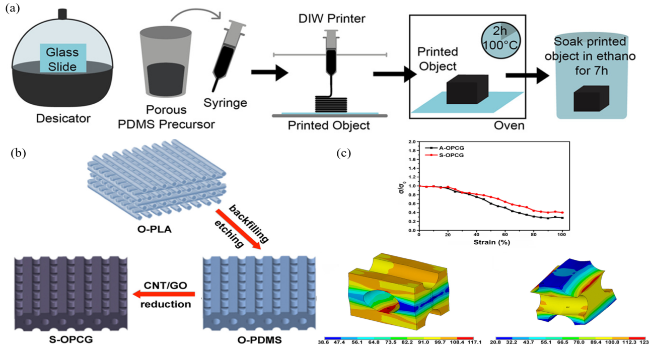
图4 (a)多孔PDMS前驱体的制备和印刷的分步过程[48];(b)S-OPCG制备示意图;(c)S-OPCG和A-OPCG的归一化电导率随拉伸应变的变化,以及100%拉伸下对齐O-PDMS分层O-PDMS模型的应变分布[49]

Fig.4 (a) The step-by-step process of preparation and printing of porous PDMS precursors[48];(b) Schematic diagram of S-OPCG preparation;(c) The change of normalized conductivity of S-OPCG and A-OPCG with tensile strain,and the strain distribution of aligned O-PDMS stratified O-PDMS models at 100% tensile[49]

Although many porous PDMS materials with complex structures have been fabricated using 3D printing technology, there are still challenges in the practical fabrication of pore structures due to the low elastic modulus of PDMS prepolymers. Additionally, the equipment used for 3D printing is expensive, and the overall fabrication process is time-consuming, which has limited its widespread application. Further research and improvements by the broader academic community are still required[50].

3.1.2 Phase Separation Techniques

Phase separation technique involves mixing two or more immiscible liquids and inducing phase separation under specific conditions, which can form a porous structure within the material. Researchers can control the shape, size, and distribution of pores in polymers by adjusting factors such as solvents and additives[51]. Compared to other preparation methods, its greatest advantage is that the pore size is not affected by templates[52]. There are various types of phase separation techniques, among which solvent evaporation-induced phase separation stands out for constructing porous structures in PDMS materials[53]. As shown in Figure 5(a), Jung et al.[54] developed a method for producing porous rubber. In this method, an emulsifier and organic solvent were first uniformly mixed through stirring to form a well-dispersed reverse micellar solution. Then, the micellar solution was added into a PDMS prepolymer containing multi-walled carbon nanotubes (MWNTs), and stirred to produce a gel-like solution. Subsequently, it was poured into a mold to form a thin film, while a nozzle was used to create patterns. Finally, during heating and curing, the micelles coalesced and were simultaneously evaporated and removed, resulting in a porous structure within the film. The pore sizes generated through this process ranged from tens of micrometers to several millimeters, with the exact size being influenced comprehensively by the type of organic solvent, the volume of the emulsion added to the PDMS prepolymer, and the temperature.
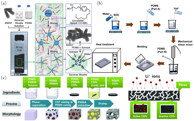
图5 (a)将MWNT、RMS和PDMS混合,在超声下分散并搅拌混合过程的示意图[54];(b)PDMS和四氢呋喃溶液的制备和成型[55];(c)多孔PDMS-CNT纳米复合材料的制备过程与PDMS-CNT纳米复合材料的示意图[56]

Fig.5 (a) Schematic diagram of mixing MWNT,RMS and PDMS,dispersing under ultrasound and stirring [54];(b) Preparation and molding of PDMS and tetrahydrofuran solution [55];(c) Preparation process of porous PDMS-CNT nanocomposites and schematic diagram of PDMS-CNT nanocomposites [56]

Abshirini et al.[55] investigated the effects of PDMS concentration and water/THF content on pore size distribution, mechanical behavior, and porosity of samples by preparing a ternary system solution of water/tetrahydrofuran/PDMS at different concentrations and subsequently creating pore structures through solvent removal during stepwise thermal treatment. Porous PDMS with a wide range of pore size distributions and mechanical properties was prepared by adjusting the non-solvent/solvent ratio in the developed method (Fig. 5(b)). Lee et al.[56] also proposed a novel phase separation method for producing porous CNT/PDMS by introducing and inducing the removal of polymethyl methacrylate (PMMA) from PDMS; the pore structure size and distribution were optimized by adjusting the ratio between added PMMA and PDMS. The prepared porous nanocomposite CNT/PDMS exhibited excellent mechanical and electrochemical properties (Fig. 5(c)).

3.1.3 Template Removal Method

As a simple, non-harmful, and commonly used method for manufacturing porous PDMS materials, the template removal method employs various solid templates. Typically, after selectively dissolving and removing the template, pore structures can be left within the PDMS material[57].
At present, various solid templates are widely used in research, including zinc oxide, sugar particles, salt micro-particles, and nickel foam[58-61]. As shown in Fig. 6(a) and 6(b)[62-63], the preparation process when using this type of solid template involves adding the template into a container, followed by mixing PDMS prepolymer and curing agent at a mass ratio of 10:1 uniformly, then thoroughly mixing this mixture with the template. Subsequently, bubbles are removed under vacuum to facilitate the infiltration of the prepolymer into the template. After PDMS has cured for a certain period, it is immersed in a solvent to remove the template, thereby forming porous PDMS material. In this technique, the pore size, pore distribution, and porosity of the PDMS material can be controlled by adjusting the mixing ratio between the PDMS prepolymer solution and the template. As illustrated in Fig. 6(c), Wu et al.[64] prepared a porous PDMS/AgNWs film by removing NaCl particles, and based on this film, they ultimately fabricated a self-powered sensor and an energy harvester. In their experiments, they adjusted the mechanical and electrical properties of the FS-TENG by varying the mixing ratio of the PDMS precursor and NaCl particles. Additionally, multiple characterization techniques confirmed the feasibility of this method.
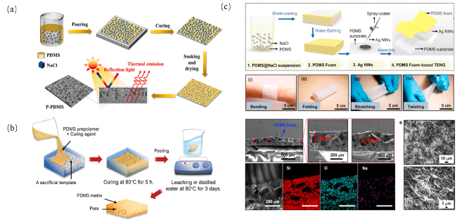
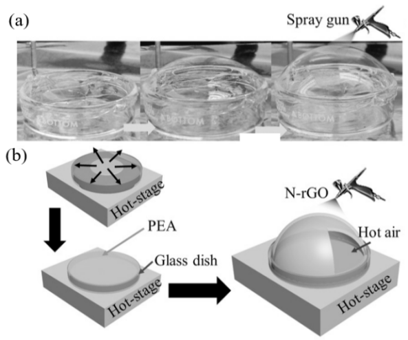
图6 (a)以NaCl为去除模板的多孔PDMS制备示意图;(b)多孔PDMS海绵制备示意图[62-63];(c)PDMS泡沫和柔性和可拉伸的摩擦电纳米发电机的制造过程示意图、薄PDMS泡沫在不同机械变形下的光学图像、PDMS泡沫的横截面SEM图像和用200 μm的比例尺对PDMS泡沫的Si、O和Na元素进行能量色散谱图[64]

Fig.6 (a) Schematic diagram of preparing porous PDMS with NaCl as the removal template;(b) Preparation diagram of porous PDMS sponge[62-63];(c) Manufacturing process diagram of PDMS foam and flexible and stretchable triboelectric nanogenerators,optical images of thin PDMS foam under different mechanical deformation,SEM images of cross section of PDMS foam and energy dispersion spectra of Si,O and Na elements of PDMS foam with a scale of 200 μm[64]

Other sacrificial templates have also emerged, for example colloidal crystal templates with specific structures have recently been used to create fine porous structures. Colloidal crystal templates can produce a wide range of ordered, periodically repeated pore structures and offer unique advantages in preparing hierarchical pore structures by not only introducing voids from assembled colloids but also generating additional pores, significantly increasing the porosity of the material. Stein et al.[59] prepared hierarchical pore structures by combining CCT with other templating techniques, and synthesized porous nanoparticles via the CCT method as templates, subsequently fabricating pore structures through precursor infiltration and template removal (see Fig. 7(a)). Kang et al.[65] fabricated PDMS sponges with different pore sizes using multilayer polystyrene (PS) microbeads. The main process involved first stacking polymer beads on a silicon substrate, then coating a PDMS film onto the stacked beads on the substrate, followed by dissolving the polymer beads and transferring the porous PDMS film to an electrode. Finally, multilayer PS beads were stacked on a substrate via drop-casting to prepare a PDMS porous sponge with an ordered face-centered cubic structure. The resulting porous PDMS sponge was then coated onto indium tin oxide (ITO)/polyethylene terephthalate (PET) films to serve as electrodes for constructing highly sensitive porous structured flexible pressure sensors (see Fig. 7(b)). This sensor achieves high sensitivity while maintaining a low detection limit and enables real-time sensing, demonstrating potential for applications in flexible wearable devices.
图7 (a)胶体晶体模板制备周期性大孔结构的3种方法[59];(b)以PS微珠为模板制备PDMS多孔结构的示意图[65]

Fig.7 (a) Three methods for preparing periodic macroporous structures from colloidal crystal templates[59];(b) Schematic diagram of PDMS porous structure prepared using PS microbeads as template[65]

3.1.4 Chemical Foaming Method

The chemical foaming method involves adding chemical foaming agents into PDMS materials, utilizing the characteristic of the foaming agents to decompose and generate gas under specific conditions to form a porous structure, which has advantages of low cost and simple procedure[66-68]. As shown in Fig. 8(a), Long et al.[68] employed ammonium bicarbonate powder as a foaming agent with PDMS as the matrix material and graphene as the conductive filler, using the chemical foaming method to produce porous structures by decomposing NH4HCO3 powder into ammonia and carbon dioxide gases at high temperatures. Additionally, based on the prepared porous graphene/PDMS composite materials, strain sensors were assembled, demonstrating excellent mechanical and sensing properties. Cao et al.[69] prepared porous pure PDMS, (GO)-PDMS, and (GONR)-PDMS by employing aqueous solutions of GONR or GO at different concentrations as foaming agents. The pore sizes produced via the chemical foaming method varied between 200~500 μm depending on the proportion of the foaming agent used (see Fig. 8(b) and 8(c)).
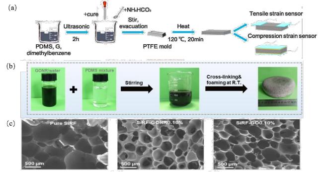
图8 (a)多孔石墨烯/PDMS复合材料的制备方法和两种传感器的组装示意图[68];(b)硅橡胶泡沫(SiRF)纳米复合材料的制备工艺和示意图;(c)纯SiRF、SiRF-GONR0.10%和SiRF-GO0.10%的SEM图像[69]

Fig.8 (a) The preparation method of the porous graphene /PDMS composite and the assembly diagram of the two sensors[68];(b) Preparation process and schematic diagram of silicone rubber foam (SiRF) nanocomposites;(c) SEM images of pure SiRF,SIRF-GONR0.10% and SIRF-GO0.10% [69]

In addition to the aforementioned methods, there are several other auxiliary shaping techniques for introducing porous structures into PDMS materials, such as ice-template freeze-drying, biomimetic templating, and pressure steam-assisted pore formation[70-71]. However, each method has its own unique advantages, disadvantages, and applicable scenarios. When selecting a specific method, it is necessary to comprehensively consider factors such as actual requirements, cost budget, and technical conditions in order to achieve an optimal solution.

3.2 Surface Micro- and Nanostructures

In addition to introducing porous structures into PDMS materials, another feasible approach to enhance the performance of flexible pressure sensors is to construct micro/nanostructures on the PDMS material surface[72]. After constructing micro/nanostructures on the PDMS surface, when the sensor is subjected to external pressure, the presence of the micro/nanostructures causes localized geometric deformation within the material, thereby increasing the change in contact area between surface conductive elements and making the variation in electrical signals more pronounced, thus enabling real-time monitoring of external pressure.
So far, researchers have developed various micro/nanostructures to enhance the sensitivity of sensors, including pyramids, wrinkles, cylinders, and spheres[73-77]. Studies have shown that micro/nanostructuring of PDMS is an effective approach to improve sensing performance such as the sensitivity of flexible pressure sensors[78].

3.2.1 Micro-pyramid Structure

Flexible pressure sensors based on micro-pyramid structures mainly detect pressure through the deformation of micro-pyramid arrays, and such sensors typically exhibit high sensitivity and a wide pressure range[79]. Tee et al.[80] used potassium hydroxide to etch silicon molds and fabricated templates with micro-pyramid structures using photolithography technology. By leveraging the elastic properties of PDMS to replicate the micro-pyramid structure, they prepared a soft mold and ultimately produced a dielectric layer with a uniform distribution of micro-pyramids on its surface. They further discussed the relationship between the shape, size, and distribution of the micro/nanostructures and the sensor's sensitivity, and applied the resulting material in a capacitive flexible sensor, performing corresponding characterizations (see Figure 9(a)).
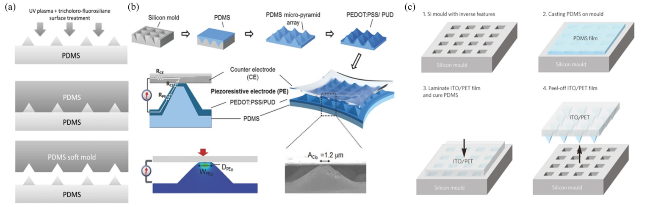
图9 (a)软PDMS模具的工艺示意图[80];(b)在金字塔表面涂覆PEDOT:PSS/PUD薄膜以及对传感器传感原理进行有限元分析示意图[81];(c)微纳结构PDMS薄膜的制备示意图[79]

Fig.9 (a) Process diagram of the soft PDMS mold [80];(b) Coating the pyramid surface with PEDOT: PSS/PUD film and finite element analysis of the sensor sensing principle [81];(c) Schematic diagram of preparation of micro-nano PDMS films [79]

To improve sensitivity while expanding the detection range of flexible sensors, Park et al.[81] fabricated a stretchable resistive flexible pressure sensor with a micro-pyramid structure. The fabrication process involved mixing PDMS prepolymer and curing agent at a mass ratio of 10:1, followed by pouring the mixture onto a substrate with a micro-pyramid structure. After curing for a certain period, the micro-pyramid structured PDMS was obtained. Subsequently, the PDMS was treated with UV ozone and then immersed in PUD solution. Finally, the resistive pressure sensor was obtained after annealing at 70 °C for 30 min. Due to the presence of the micro/nano-structured substrate, the sensor exhibited higher sensitivity and stretchability, achieving a sensitivity of up to 10.3 kPa-1 when deformed by 40%, and capable of detecting external forces as low as 23 Pa (Fig. 9(b)). To mimic the tactile properties of skin, Mannsfeld et al.[79] introduced micro-pyramid structures on the surface of PDMS films using a topological model (Fig. 9(c)). Their study revealed that the pressure sensitivity of the micro/nano-structured film significantly exceeded that of unstructured elastic films of similar thickness. Additionally, they fabricated a capacitive pressure sensor with high sensitivity and ultra-fast response time by laminating an indium tin oxide (ITO)-coated conductive flexible polyethylene terephthalate (PET) sheet onto the surface of the PDMS film.

3.2.2 Microfold Structure

Inspired by various natural phenomena such as human skin, nacre layers in shells, and ripples in dunes, researchers have gradually begun to study the formation of wrinkles, an unstable pattern, on thin film surfaces[82].
Mu et al.[83] proposed a method for fabricating hierarchical wrinkled transparent conductors based on the "balloon blowing" approach. As shown in Figure 10, this method initially prepared a dispersed rGO solution, followed by biaxial stretching of a circular glass dish coated with a polyacrylate substrate to form a film. During this process, a closed space was formed. Subsequently, the glass dish was heated, causing further expansion of the polymer film. Finally, after maintaining a constant hemispherical volume, N-rGO nanosheets were sprayed onto the expanded PEA substrate surface, resulting in a highly elastic reduced graphene oxide (rGO)/polyacrylate hierarchical wrinkled elastic transparent conductor (HWETC). The periodic hierarchical N-rGO layer wrinkles enable the HWETC to exhibit high electrical conductivity (100~457 Ω-1) and transmittance (67%~85%), allowing sensing capabilities under various deformations such as tensile bending.
图10 (a)分层皱纹弹性透明导体生产工艺;(b)HWETC制备的步骤和示意图[83]

Fig.10 (a) production process of layered corrugated elastic transparent conductor;(b) Steps and diagrams of HWETC preparation [83]

3.2.3 Microcylinder Structure

By introducing a micro-cylinder structure, a template with cylindrical structures is first prepared through certain methods, and then introduced by means of flexible materials such as PDMS. Subsequently, composites are fabricated by combining with other materials through specific bonding methods and applied to flexible sensors[84].
Chen et al.[85] prepared a flexible sensor based on a P(VDF-TrFE) microcylinder structured material for multi-touch and distributed force sensing applications. Using nanoimprint technology, a PDMS imprinting template with a uniformly distributed cylindrical array was fabricated (Fig. 11(a)), which was subsequently used to imprint the sensing film into a vertically aligned micropillar array, effectively enhancing the monitoring sensitivity.
图11 (a)软PDMS压印模板的照片;(b)纳米压印制备柔性传感器的过程[85]

Fig.11 (a) Photographs of the template imprinted by soft PDMS;(b) Process for preparing flexible sensors by nanocompression printing[85]

As shown in Fig. 11(b), a large-area flexible sensor array with 12×12 sensing array units was fabricated by sandwiching piezoelectric micro-pillar arrays between patterned electrode arrays and columnar electrode arrays. The cylindrical structured sensor arrays were proven to exhibit higher sensitivity compared to planar thin films. They also demonstrated robust stability and good inter-pixel uniformity during fatigue testing.

3.2.4 Microsphere Structure

To overcome the low sensitivity of traditional piezoresistive sensors and the response lag and hysteresis caused by the viscoelastic nature of PDMS material itself, Bae et al.[86] patterned copper sheets into an inverted dome shape using photolithography, and then grew graphene on their surfaces via chemical vapor deposition. Finally, after molding PDMS and etching the copper sheets, a hierarchical structured array fully covered with graphene was obtained (Fig. 12(a)). Using the prepared PDMS material coated with monolayer graphene, a high-performance piezoresistive pressure sensor was fabricated (Fig. 12(b)), which exhibited an excellent comprehensive sensing performance with a linear relationship between applied pressure and output, including a high sensitivity of 8.5 kPa-1, a wide monitoring range of 0-12 kPa, high durability over 10,000 cycles, a low detection limit of 1 Pa, and an operating voltage as low as 1 V, demonstrating great potential for electronic skin applications. As shown in Fig. 12(c), Park et al.[87] designed and fabricated an elastic composite film with microsphere structures. First, a dispersed MWNT solution was uniformly mixed with PDMS material, followed by heating to remove the chloroform solvent. Subsequently, hexane and curing agent were added, and the mixture was poured into a silicon mold with micro/nanostructures for curing and demolding, resulting in a flexible conductive PDMS/CNT material with microsphere structures. Through this method, the contact area of the sensor under force was increased, thereby exhibiting high sensitivity (15.1 kPa-1), low detection limit (0.2 Pa), and fast response time (0.04 s). It is evident that although regular structures such as cylinders, pyramids, and wrinkles have improved sensor performance to some extent, their templates with micro/nanostructures are mostly fabricated through Si template etching and printing. This fabrication approach not only involves complicated processes but also significantly increases production costs.
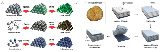
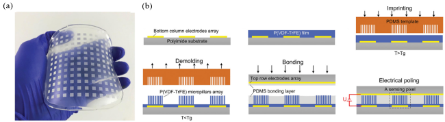
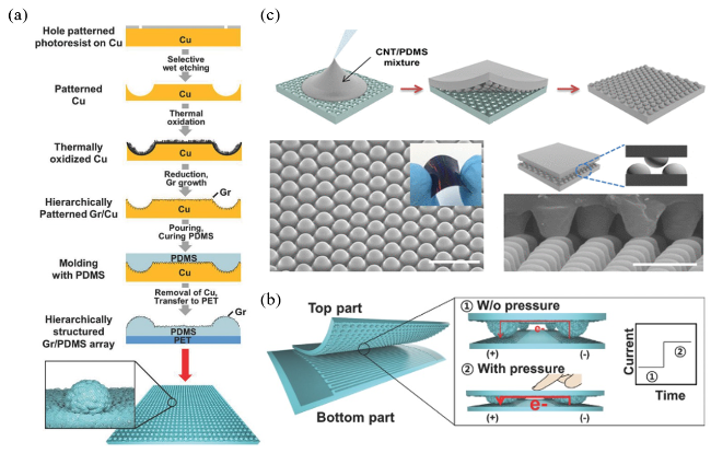
图12 (a)微球体弹性层整体制造过程示意图;(b)由分层石墨烯/PDMS阵列组成的压力传感器的传感器组装和工作原理示意图[86];(c)具有微球阵列的CNT复合弹性体的制造过程与复合弹性体的SEM图像[87]

Fig.12 (a) Schematic diagram of the overall manufacturing process of the microsphere elastic layer;(b) Schematic diagram of sensor assembly and working principle of a pressure sensor consisting of a layered graphene /PDMS array [86];(c) Fabrication process of CNT composite elastomer with microsphere array and SEM images of the composite elastomer [87]

At present, researchers have also proposed various naturally existing templates in society to improve the performance of sensors, such as biomimetic fish scales[88], sandpaper[89], lotus leaf surfaces[90], and spine-like structures[91]. Although different micro/nanostructures have certain differences in their impact on sensor performance, they all contribute to enhancing the overall sensing capabilities of the final fabricated flexible sensors. Additionally, depending on the sensing mechanism, constructing surface micro/nanostructures influences performance differently; diverse and complex micro/nanostructures continue emerging. However, their fundamental principle is expanding the electrical signals generated by mechanical forces through the introduction of micro/nanostructures, thereby enabling sensors to monitor changes under smaller external forces, thus improving sensitivity, broadening detection range, and lowering detection limits. Furthermore, introducing micro/nanostructures also enhances mechanical properties. PDMS materials with micro/nanostructuring demonstrate exceptional flexibility and stretchability, increasing their potential application in wearable electronics.
The above introduces two methods for improving the performance of PDMS-based flexible pressure sensors: incorporating pore structures and constructing surface micro/nanostructures. However, researchers are not satisfied with the current state of flexible sensor development, because performance improvements achieved through single means or preparation of individual structures can no longer meet their higher performance requirements. To enhance the performance of flexible sensors, various composite approaches have currently emerged, such as multiscale porous structures prepared via different methods, multiple combinations of micropores, mesopores, and macropores, bi-modal mesopores, and hierarchical porous structures[92], integrating porous structures with surface micro/nanostructures[93], and introducing hierarchical multiscale porous structures and hierarchical multiscale micro/nanostructures[94-95]. A comparison of fabrication processes and performance of PDMS flexible pressure sensors with different porous structures and microstructures is detailed in Table 3, which intuitively illustrates process conditions and performance differences among various structures during actual fabrication. In addition to basic structural design, surface modification and surface functionalization of PDMS materials also represent another strategy for improving sensor performance[96]. In practical applications, suitable methods should be explored based on actual needs, budget constraints, and other factors.
表3 不同结构的PDMS柔性压力传感器的性能

Table 3 Performance of PDMS flexible pressure sensors with different structures

Basal
material
Preparation technique Sensitivity/kPa-1 Detection range/kPa(Detection
limit/Pa)
Response time/ms Cycle stability/times Ref
Graphene/PDMS Pore structure (chemical foaming method) 68,770 / ~200 1000 64
MWCNT/PDMS Pore structure (direct sacrifice template method) 2.155 0~500(50) / 2500 68
Ag/PDMS Surface micro-nano structure (Micropyramid) 259.32 0~54(0.36) ~0.2 / 69
CNT/PDMS Surface micro-nano structure (micro-fold) 90,657 0~26 ~12 1000 70
Au/PDMS Surface micro-nano structure (microspheres) 196 0~100(0.5) ~26 10 000 71
Au/PDMS+PET/CPAn Surface micro-nano structure (microcylinder) 2.0 0~0.22(15) ~50 10 000 72
CNT/PDMS Surface micro-nano structure (microsphere) + pore structure (sacrificial template method) 15. 0~30(0.2) ~40 / 73
PEDOT/PDMS Surface micro-nano structure (Micropyramid) 10.3 0~8(23) / / 77
AgNWs/PDMS Surface micro-nano structure (microsphere) + pore structure (sacrificial template method) 3788.2 0~220(0.83) ~100 22 000 89
MWCNT/PDMS Surface micro-nano structure (micropyramid) + pore structure (sacrificial template method) 83.9 0~10(0.5) ~170 28 000 95

4 Application of PDMS-based Flexible Pressure Sensors

4.1 Health Monitoring

In the field of modern medical care and health management, precise and continuous monitoring of human physiological information is becoming increasingly critical. Traditional monitoring methods often have many limitations, such as poor comfort and the inability to provide real-time monitoring. The emergence of flexible pressure sensors has brought a ray of hope, illuminating a new path for health monitoring (Fig. 13(a)). With advantages including high sensitivity, fast response speed, low hysteresis, and wide monitoring range, flexible pressure sensors have revolutionized health monitoring practices. They can closely adhere to human skin, adapting to body movements and physiological changes like an invisible sensing network, and are capable of capturing subtle pressure variations during daily activities, body movements during sleep, and heartbeat signals. This highly sensitive characteristic enables more comprehensive and accurate monitoring of physiological behaviors and states, opening up a brand-new avenue for health monitoring. Guo et al. constructed the electrode layer and encapsulation layer of a flexible sensor by adhering conductive copper foil onto the surface of plain cotton fabric. They successfully prepared a porous PDMS sponge using the sodium chloride (NaCl) templating method. Subsequently, functionalization modification of the porous sponge was conducted with carbon nanotubes (CNTs) to form a high-performance piezoresistive layer, ultimately achieving fabrication of a porous PDMS/CNTs composite piezoresistive flexible pressure sensor. In performance evaluation tests, participants underwent monitoring during four consecutive swallowing actions. The results showed that the obtained pressure signal curves exhibited a high degree of similarity in waveform, demonstrating stable and repeatable response characteristics. This result indicates that the sensor can accurately identify throat swallowing motions and possesses excellent dynamic monitoring capabilities. Based on its favorable flexibility and high sensitivity, this sensor demonstrates broad application prospects in medical fields such as health monitoring, rehabilitation assessment, and dysphagia diagnosis. Pang et al. designed and fabricated a flexible sensor array featuring a stretchable matrix network structure. Each sensing unit is interconnected through specific structures, enabling simultaneous, non-interfering monitoring of various parameters including pressure, strain, temperature, humidity, proximity, thermal, magnetic, and optical changes (as shown in Fig. 13(b)). By introducing micro-pyramid structures into PDMS, the sensor's sensitivity was effectively improved while reducing the negative impact caused by PDMS hysteresis. Combining PEN substrates with PDMS not only enhances flexibility but also imparts biocompatibility when applied to the human body.
图13 (a)柔性传感器在健康监测方面的应用[97];(b)监测人体喉咙发声的示意图[100]

Fig.13 (a) The application of flexible sensors in health monitoring[97];(b) Schematic diagram of detecting vocalizations in the human throat[100]

In medical applications, this sensor can be used to monitor arterial tonometry, neck pulse, and assist in the treatment of cardiovascular diseases, demonstrating its unique advantages in intelligent healthcare and biomedical monitoring.

4.2 Electronic Skin

As a cutting-edge technological product, flexible sensors have demonstrated extraordinary value in the field of tactile sensing for electronic skin and have already gained widespread application[101]. Electronic skin represents a highly innovative concept that achieves remarkable functional expansion through the use of flexible sensors. Acting as the "nerve endings" of electronic skin, flexible sensors can be processed into various shapes after being attached to human body or robot surfaces, thereby mimicking human sensory functions, accurately monitoring physiological information, and endowing robots with tactile perception capabilities. Hua et al.[102] proposed a skin-inspired highly stretchable and conformal matrix network (SCMN) as a multifunctional electronic skin system capable of simultaneously detecting multiple external stimuli such as temperature, in-plane strain, relative humidity (RH), ultraviolet (UV) light, magnetic fields, pressure, and proximity, demonstrating excellent multimodal sensing performance. This electronic skin not only features adjustable sensing ranges but also enables large-area scalability, showing promise for applications in high-density three-dimensional (3D) integrated systems. Moreover, researchers have developed a personalized smart prosthetic hand for touch and temperature sensing that can monitor pressure distribution on fingers in real time while estimating the temperature of grasped objects (as shown in Figure 14(a)). This technology opens up new perspectives for the application of electronic skins in fields such as bionics, human augmentation, and intelligent prosthetics, revealing significant potential for future applications.
图14 (a)传感器用于人体手臂表面以及腹部皮肤[102];(b)电子皮肤与人体皮肤的基本结构 [103]

Fig.14 (a) The sensor is used on the surface of the human arm and on the skin of the abdomen[102];(b) The basic structure of electronic skin and human skin[103]

As shown in Fig. 14(b), Chen et al.[103] fabricated a double-helix CNT-PDMS electrode and substrate. Based on the triboelectric effect, when the double-helix CNT-PDMS electrode slides across surfaces with different roughness, it generates alternating current voltages with varying frequencies to monitor sliding movements, simulating fingerprints, while simultaneously incorporating slow-adaptation (SA) functionality and a dermal structure. Due to its capability to sense both pressure and sliding, robots equipped with this sensor can perform more complex tasks, such as roughness monitoring and gripping/releasing soft bottles. This biomimetic electronic skin structure provides a novel approach for integrating different sensing mechanisms, leveraging the unique characteristics of triboelectric and piezoresistive sensing to achieve multifunctionality and demonstrating application potential across various fields.

5 Conclusion and Prospect

This paper focuses on the research progress of flexible pressure sensors prepared based on PDMS materials, particularly discussing the advantages of PDMS as a flexible substrate in flexible pressure sensing, as well as methods for improving the sensitivity of pressure sensors and expanding the monitoring range.
At present, traditional fabrication techniques for flexible pressure sensors have matured, while emerging technologies continue to emerge, showing a trend of diversification. Although sensors featuring low cost, high sensitivity, fast response time, wide measurement range, and stability have been successfully developed, flexible pressure sensors still face many challenges in practical applications. These include the balance between high sensitivity and wide monitoring range, as well as insufficient measurement accuracy caused by structural limitations, making them yet unable to fully match the performance of traditional metal and semiconductor sensors. Therefore, future research on flexible pressure sensors based on PDMS materials will focus on the following aspects.
(1) Further improve sensor performance by focusing on the design of two key factors: material composites and internal structure. Regarding material composites, thoroughly investigate the composite methods of various types and sizes of nanomaterials such as graphene, carbon nanotubes, and conductive polymers with PDMS, and consider the introduction of novel fabrication processes. In terms of internal structure, expand the application of structures such as nanopillar arrays, precisely control parameters using micro/nanofabrication techniques, and combine simulations with experimental analyses to study the mechanical and electrical response mechanisms of these internal structures under pressure, thereby enabling precise regulation of sensor performance.
(2) Develop a multi-functional integrated sensor array by incorporating various types of sensors such as gas and chemical sensors to achieve multi-function monitoring. Investigate novel sensing mechanisms that enable the sensors to generate specific responses to multiple parameters. Furthermore, conduct in-depth research on the interference issues among different functional sensors and develop compensation algorithms or isolation techniques. Meanwhile, design flexible and adaptable layout schemes and employ relevant technologies to enhance wearing comfort and aesthetics.
(3) Enhance the long-term stability and durability of sensors by exploring novel self-healing material systems applicable to PDMS-based sensors, investigating their performance indicators, and improving healing properties through the addition of nanofillers. Utilize microstructural analysis to understand the healing mechanism, while improving protective coating technologies by developing multilayer composite coating systems, applying nanotechnology for coating modification to enhance oxidation resistance, ultraviolet resistance, self-cleaning, and anti-pollution capabilities.
(4) Promote the development of PDMS flexible sensors toward self-powered directions. Conduct in-depth studies on the microscopic mechanisms of triboelectric and piezoelectric effects, select suitable materials, and perform micro/nano-structured surface treatments. Design hybrid self-powered systems combined with other energy harvesting technologies to ensure continuous and stable power supply.
(5) The biocompatibility of PDMS-based flexible sensors can be improved through optimized design. Physical and chemical methods for PDMS surface treatment can promote cell attachment and growth. For example, oxygen plasma treatment and the introduction of functional groups can enhance cell adhesion and proliferation on its surface, reducing adverse effects on the organism, and creating conditions for the sensor to work for extended periods in a stable and safe manner within biomedical applications, thereby better performing monitoring functions.
[1]
Zhang J W, Zhang Y, Li Y Y, Ye X, Wang P, Xu Y K. ACS Appl. Electron. Mater., 2021, 3(7): 3177.

[2]
Hosseini E S, Manjakkal L, Shakthivel D, Dahiya R. ACS Appl. Mater. Interfaces, 2020, 12(8): 9008.

[3]
Ha K H, Zhang W Y, Jang H, Kang S, Wang L, Tan P, Hwang H, Lu N S. Adv. Mater., 2021, 33(48): 2103320.

[4]
Hu Y F, Zheng Z J. Nano Energy, 2019, 56: 16.

[5]
Liu Z Y, Wang H, Huang P G, Huang J P, Zhang Y, Wang Y Y, Yu M, Chen S X, Qi D P, Wang T, Jiang Y, Chen G, Hu G Y, Li W L, Yu J C, Luo Y F, Loh X J, Liedberg B, Li G L, Chen X D. Adv. Mater., 2019, 31(35): 1901360.

[6]
Bartlett M D, Dickey M D, Majidi C. NPG Asia Mater., 2019, 11: 21.

[7]
Kang J, Tok J B, Bao Z N. Nat. Electron., 2019, 2(4): 144.

[8]
Tang X, Wu C Y, Gan L, Zhang T, Zhou T T, Huang J, Wang H, Xie C S, Zeng D W. Small, 2019, 15(10): 1804559.

[9]
Dan L, Shi S, Chung H J, Elias A. ACS Appl. Nano Mater., 2019, 2(8): 4869.

[10]
Gao J, Zhao B, Chen X, Gu M, Zhang W, Wang L, Wei L, Yang C, Chen M. Small, 2024, 19: 5772.

[11]
Gu M X, Zhao B Z, Gao J X, Zhou X, Huang L C, Wang J H, Wei L, Yang C L, Chen M. Adv. Funct. Mater., 2024, 34(33): 2400494.

[12]
He C Y, Wu L, Gu G Q, Wei L, Yang C L, Chen M. Nano Lett., 2024, 24(23): 7040.

[13]
Hou Y X, Wang L, Sun R, Zhang Y A, Gu M X, Zhu Y H, Tong Y B, Liu X Y, Wang Z X, Xia J, Hu Y G, Wei L, Yang C L, Chen M. ACS Nano, 2022, 16(5): 8358.

[14]
Wang Z R, Wang S, Zeng J F, Ren X C, Chee A J Y, Yiu B Y S, Chung W C, Yang Y, Yu A C H, Roberts R C, Tsang A C O, Chow K W, Chan P K L. Small, 2016, 12(28): 3827.

[15]
Zhu Y S, Cai H B, Ding H Y, Pan N, Wang X P. ACS Appl. Mater. Interfaces, 2019, 11(6): 6195.

[16]
Li H W, Wu K J, Xu Z Y, Wang Z W, Meng Y C, Li L Q. ACS Appl. Mater. Interfaces, 2018, 10(24): 20826.

[17]
Ha M, Lim S, Cho S, Lee Y, Na S Y, Baig C, Ko H. ACS Nano, 2018, 12(4): 3964.

[18]
Dalla Monta A, Razan F, Le Cam J B, Chagnon G. Sens. Actuat. A Phys., 2018, 280: 107.

[19]
Giri R, Naskar K, Nando G B. Radiat. Phys. Chem., 2012, 81(12): 1930.

[20]
Montazerian H, Mohamed M G A, Montazeri M M, Kheiri S, Milani A S, Kim K, Hoorfar M. Acta Biomater., 2019, 96: 149.

[21]
Shi Y L, Hu M, Xing Y F, Li Y H. Mater. Des., 2020, 185: 108219.

[22]
Chen X D. Small Meth., 2017, 1(4): 1600029.

[23]
Xu S, Zhang Y H, Jia L, Mathewson K E, Jang K I, Kim J, Fu H R, Huang X, Chava P, Wang R H, Bhole S, Wang L Z, Na Y J, Guan Y, Flavin M, Han Z S, Huang Y G, Rogers J A. Science, 2014, 344(6179): 70.

[24]
Mishra S, Mohanty S, Ramadoss A. ACS Sens., 2022, 7(9): 2495.

[25]
Takei K, Takahashi T, Ho J C, Ko H, Gillies A G, Leu P W, Fearing R S, Javey A. Nat. Mater., 2010, 9(10): 821.

[26]
Shi M Y, Zhang J X, Chen H T, Han M D, Shankaregowda S A, Su Z M, Meng B, Cheng X L, Zhang H X. ACS Nano, 2016, 10(4): 4083.

[27]
Park S, Kim H, Vosgueritchian M, Cheon S, Kim H, Koo J H, Kim T R, Lee S, Schwartz G, Chang H, Bao Z N. Adv. Mater., 2014, 26(43): 7324.

[28]
Wang J L, Lu C H, Zhang K. Energy Environ. Mater., 2020, 3(1): 80.

[29]
Wang C, Hwang D, Yu Z B, Takei K, Park J, Chen T, Ma B W, Javey A. Nat. Mater., 2013, 12(10): 899.

[30]
Gao Q, Cheng T H, Wang Z L. Extreme Mech. Lett., 2021, 42: 101100.

[31]
Zhan J, Wang Z Y, Mo L X, Meng X Y, Li L H, Peng Z C. Prog. Chem., 2022, 34(10): 2202.

( (赵静, 王子娅, 莫黎昕, 孟祥有, 李路海, 彭争春. 化学进展, 2022, 34(10): 2202.)

[32]
Gong S, Schwalb W, Wang Y W, Chen Y, Tang Y, Si J, Shirinzadeh B, Cheng W L. Nat. Commun., 2014, 5: 3132.

[33]
Shuai X T, Zhu P L, Zeng W J, Hu Y G, Liang X W, Zhang Y, Sun R, Wong C P. ACS Appl. Mater. Interfaces, 2017, 9(31): 26314.

[34]
Kim J, Lee M, Shim H J, Ghaffari R, Cho H R, Son D, Jung Y H, Soh M, Choi C, Jung S, Chu K, Jeon D, Lee S T, Kim J H, Choi S H, Hyeon T, Kim D H. Nat. Commun., 2014, 5: 5747.

[35]
Wan S, Bi H C, Zhou Y L, Xie X, Su S, Yin K B, Sun L T. Carbon, 2017, 114: 209.

[36]
Sarwar M S, Dobashi Y, Preston C, Wyss J K M, Mirabbasi S, Madden J D W. Sci. Adv., 2017, 3(3): e1602200.

[37]
Kim H, Kim G, Kim T, Lee S, Kang D, Hwang M S, Chae Y, Kang S, Lee H, Park H G, Shim W. Small, 2018, 14(8): 1703432.

[38]
He Z Z, Gao B B, Li T, Liao J L, Liu B, Liu X J, Wang C Y, Feng Z Q, Gu Z Z. ACS Sustainable Chem. Eng., 2019, 7(1): 1745.

[39]
Sultana A, Alam M M, Garain S, Sinha T K, Middya T R, Mandal D. ACS Appl. Mater. Interfaces, 2015, 7(34): 19091.

[40]
Fan F R, Tian Z Q, Wang Z L. Nano Energy, 2012, 1(2): 328.

[41]
Viry L, Levi A, Totaro M, Mondini A, Mattoli V, Mazzolai B, Beccai L. Adv. Mater., 2014, 26(17): 2659.

[42]
Das S, Heasman P, Ben T, Qiu S L. Chem. Rev., 2017, 117(3): 1515.

[43]
Slater A G, Cooper A I. Science, 2015, 348(6238): aaa8075.

[44]
Ozkan E, Garren M, Manuel J, Douglass M, Devine R, Mondal A, Kumar A, Ashcraft M, Pandey R, Handa H. ACS Appl. Mater. Interfaces, 2023, 15(5): 7610.

[45]
Guo B F, Wang P H, Cao C F, Qu Z H, Lv L Y, Zhang G D, Gong L X, Song P G, Gao J F, Mai Y W, Tang L C. Compos. Part B Eng., 2022, 247: 110290.

[46]
Yu C L, Yu C M, Cui L Y, Song Z Y, Zhao X Y, Ma Y, Jiang L. Adv. Mater. Interfaces, 2017, 4(3): 1600862.

[47]
Hinton T J, Hudson A, Pusch K, Lee A, Feinberg A W. ACS Biomater. Sci. Eng., 2016, 2(10): 1781.

[48]
Woo R, Chen G, Zhao J Y, Bae J. ACS Appl. Polym. Mater., 2021, 3(7): 3496.

[49]
Duan S, Yang K, Wang Z, Chen M, Zhang L, Zhang H, Li C. ACS Appl. Mater. Interface, 2016, 8(3): 2187.

[50]
Oropallo W, Piegl L A. Eng. Comput., 2016, 32(1): 135.

[51]
Ishigami T, Nii Y, Ohmukai Y, Rajabzadeh S, Matsuyama H. Membranes, 2014, 4(1): 113.

[52]
Ulbricht M. Polymer, 2006, 47(7): 2217.

[53]
Kim J K, Taki K, Ohshima M. Langmuir, 2007, 23(24): 12397.

[54]
Jung S, Kim J H, Kim J, Choi S, Lee J, Park I, Hyeon T, Kim D H. Adv. Mater., 2014, 26(28): 4825.

[55]
Abshirini M, Saha M C, Altan M C, Liu Y T, Cummings L, Robison T. J. Appl. Polym. Sci., 2021, 138(29): 50688.

[56]
Lee H, Yoo J K, Park J H, Kim J H, Kang K, Jung Y S. Adv. Energy Mater., 2012, 2(8): 976.

[57]
Keller A, Zainulabdeen K, Warren H, in het Panhuis M. MRS Adv., 2022, 7(23/24): 495.

[58]
McCall W R, Kim K, Heath C, La Pierre G, Sirbuly D J. ACS Appl. Mater. Interfaces, 2014, 6(22): 19504.

[59]
Stein A, Li F, Denny N R. Chem. Mater., 2008, 20(3): 649.

[60]
Zhao X, Li L X, Li B C, Zhang J P, Wang A Q. J. Mater. Chem. A, 2014, 2(43): 18281.

[61]
Liu W, Chen Z, Zhou G M, Sun Y M, Lee H R, Liu C, Yao H B, Bao Z N, Cui Y. Adv. Mater., 2016, 28(18): 3578.

[62]
Pharino U, Sinsanong Y, Pongampai S, Charoonsuk T, Pakawanit P, Sriphan S, Vittayakorn N, Vittayakorn W. Radiat. Phys. Chem., 2021, 189: 109720.

[63]
Zhang J M, Yang X B, Xu R Z, Li S S, Qi G G, Tan X Y. Mater. Lett., 2024, 357: 135686.

[64]
Wu M, Gao Z, Yao K, Hou S, Liu Y, Li D, He J, Huang X, Song E, Yu J, Yu X. Mater. Today Energy, 2021, 20: 100657.

[65]
Kang S B, Lee J, Lee S, Kim S, Kim J K, Algadi H, Al-Sayari S, Kim D E, Kim D, Lee T. Adv. Electron. Mater., 2016, 2(12): 1600356.

[66]
Calabrese L, Bonaccorsi L, Freni A, Proverbio E. Sustain. Mater. Technol., 2017, 12: 27.

[67]
Chruściel J J, Leśniak E. J. Appl. Polym. Sci., 2011, 119(3): 1696.

[68]
Long Y, Zhao X L, Jiang X, Zhang L, Zhang H, Liu Y, Zhu H W. FlatChem, 2018, 10: 1.

[69]
Cao C F, Wang P H, Zhang J W, Guo K Y, Li Y, Xia Q Q, Zhang G D, Zhao L, Chen H, Wang L, Gao J F, Song P, Tang L C. Chem. Eng. J., 2020, 393: 124724.

[70]
Zhao D S, Li Y W, Zhang Z D, Xu T, Ye C, Shi T Q, Wang Y T. Mater. Horiz., 2023, 10(4): 1121.

[71]
Qian L, Zhang H F. J. Chem. Technol. Biotechnol., 2011, 86(2): 172.

[72]
Feng Z P, He Q, Wang X, Lin Y G, Qiu J, Wu Y F, Yang J. ACS Appl. Mater. Interfaces, 2023, 15(4): 6217.

[73]
Chen M, Li K, Cheng G M, He K, Li W W, Zhang D S, Li W M, Feng Y, Wei L, Li W J, Zhong G H, Yang C L. ACS Appl. Mater. Interfaces, 2019, 11(2): 2551.

[74]
Park J, Kim J, Hong J, Lee H, Lee Y, Cho S, Kim S W, Kim J J, Kim S Y, Ko H. NPG Asia Mater., 2018, 10(4): 163.

[75]
Wang Z H, Zhang L, Liu J, Jiang H, Li C Z. Nanoscale, 2018, 10(22): 10691.

[76]
Park H, Jeong Y R, Yun J, Hong S Y, Jin S, Lee S J, Zi G, Ha J S. ACS Nano, 2015, 9(10): 9974.

[77]
Park J, Lee Y, Hong J, Lee Y, Ha M, Jung Y, Lim H, Kim S Y, Ko H. ACS Nano, 2014, 8(12): 12020.

[78]
Trung T Q, Lee N E. Adv. Mater., 2016, 28(22): 4338.

[79]
Mannsfeld S C B, Tee B C, Stoltenberg R M, Chen C V H, Barman S, Muir B V O, Sokolov A N, Reese C, Bao Z N. Nat. Mater., 2010, 9(10): 859.

[80]
Tee B C, Chortos A, Dunn R R, Schwartz G, Eason E, Bao Z N. Adv. Funct. Mater., 2014, 24(34): 5427.

[81]
Choong C L, Shim M B, Lee B S, Jeon S, Ko D S, Kang T H, Bae J, Lee S H, Byun K E, Im J, Jeong Y J, Park C E, Park J J, Chung U I. Adv. Mater., 2014, 26(21): 3451.

[82]
Chung J Y, Nolte A J, Stafford C M. Adv. Mater., 2011, 23(3): 349.

[83]
Mu J K, Hou C Y, Wang G, Wang X M, Zhang Q H, Li Y G, Wang H Z, Zhu M F. Adv. Mater., 2016, 28(43): 9491.

[84]
Pang C, Lee G Y, Kim T I, Kim S M, Kim H N, Ahn S H, Suh K Y. Nat. Mater., 2012, 11(9): 795.

[85]
Chen X L, Shao J Y, Tian H M, Li X M, Wang C H, Luo Y S, Li S. Adv. Mater. Technol., 2020, 5(7): 2000046.

[86]
Bae G Y, Pak S W, Kim D, Lee G, Kim D H, Chung Y, Cho K. Adv. Mater., 2016, 28(26): 5300.

[87]
Park J, Lee Y, Hong J, Ha M, Jung Y D, Lim H, Kim S Y, Ko H. ACS Nano, 2014, 8(5): 4689.

[88]
Wang J, Tenjimbayashi M, Tokura Y, Park J Y, Kawase K, Li J T, Shiratori S. ACS Appl. Mater. Interfaces, 2018, 10(36): 30689.

[89]
Wang X L, Xia Z D, Zhao C, Huang P, Zhao S F, Gao M, Nie J K. Sens. Actuat. A Phys., 2020, 312: 112147.

[90]
Li T, Luo H, Qin L, Wang X W, Xiong Z P, Ding H Y, Gu Y, Liu Z, Zhang T. Small, 2016, 12(36): 5042.

[91]
Hu Y F, Huang T Q, Zhang H J, Lin H J, Zhang Y, Ke L W, Cao W, Hu K, Ding Y, Wang X Y, Rui K, Zhu J X, Huang W. ACS Appl. Mater. Interfaces, 2021, 13(20): 23905.

[92]
Bai S L, Zhang K W, Wang L S, Sun J H, Luo R X, Li D Q, Chen A F. J. Mater. Chem. A, 2014, 2(21): 7927.

[93]
Ji B, Zhou Q, Wu J B, Gao Y B, Wen W J, Zhou B P. ACS Appl. Mater. Interfaces, 2020, 12(27): 31021.

[94]
Shi L, Chu Z Y, Liu Y, Jin W Q, Xu N P. Adv. Funct. Mater., 2014, 24(44): 7032.

[95]
Xiong Y X, Hu Y G, Zhu P L, Sun R, Wang Z P. Prog. Chem., 2019, 31(6): 800.

(熊耀旭, 胡友根, 朱朋莉, 孙蓉, 汪正平. 化学进展, 2019, 31(6): 800.).

[96]
Ananthasubramanian P, Sahay R, Raghavan N. RSC Adv., 2024, 14(22): 15249.

[97]
Chen S, Song Y J, Xu F. ACS Appl. Mater. Interfaces, 2018, 10(40): 34646.

[98]
Park J, Lee Y, Ha M, Cho S, Ko H. J. Mater. Chem. B, 2016, 4(18): 2999.

[99]
Guo X L, Liu X, Hu H C, Hu C A. Light. Ind. Mach., 2023, 41(2): 34.

(郭鑫雷, 刘鑫, 胡汉春, 胡呈安. 轻工机械, 2023, 41(2): 34.).

[100]
Pang C, Koo J H, Nguyen A, Caves J M, Kim M G, Chortos A, Kim K, Wang P J, Tok J B, Bao Z N. Adv. Mater., 2015, 27(4): 634.

[101]
Kim K, Jung M, Kim B, Kim J, Shin K, Kwon O S, Jeon S. Nano Energy, 2017, 41: 301.

[102]
Hua Q L, Sun J L, Liu H T, Bao R R, Yu R M, Zhai J Y, Pan C F, Wang Z L. Nat. Commun., 2018, 9: 244.

[103]
Chen H T, Miao L M, Su Z M, Song Y, Han M D, Chen X X, Cheng X L, Chen D M, Zhang H X. Nano Energy, 2017, 40: 65.

Outlines

/