
Cellulose-Based Daytime Radiative Cooling Materials
Received date: 2024-06-21
Revised date: 2024-12-02
Online published: 2025-04-30
Supported by
Ningbo Key R&D Projects(2022Z101)
Ningbo Key R&D Projects(2023Z188)
Ningbo “3315 Innovative Team” Project
Scientific Research Foundation of NingboTech University(20200323Z0018)
With the improvement of living standard and heightened awareness of environmental protection,renewable and environmentally friendly cellulose materials have attracted much attention in the field of daytime radiative cooling due to their high mid-infrared emissivity and the advantages of tunability of hierarchical structure. In this review,the classification,advantages/disadvantages of radiative cooling materials,the principles of radiative cooling,and the factors influencing their performance are introduced. The classification,state of the art as well as radiative cooling properties of cellulose-based daytime radiative cooling materials are elaborated. The recent progress in the four main application areas including building thermal management,personal thermal management,photovoltaics and low-temperature storage/transportation are summarized. Finally,the existing challenges in the current research are discussed and the future development in this field is also envisaged.
1 Introduction
2 Radiative cooling
2.1 Principles
2.2 Influencing factors
3 Cellulose-based daytime radiative cooling materials and classification
3.1 Natural cellulose-based materials
3.2 Cellulose derivatives-based materials
3.3 Bacterial cellulose-based materials
4 Application fields
4.1 Building thermal management
4.2 Personal thermal management
4.3 Photovoltaics
4.4 Low-temperature storage/transportation
5 Conclusion and outlook
Key words: daytime radiative cooling; cellulose; cellulose derivatives; nanocellulose
Xiushuang Jiang , Junming Wang , Hongzhi Liu . Cellulose-Based Daytime Radiative Cooling Materials[J]. Progress in Chemistry, 2025 , 37(5) : 724 -742 . DOI: 10.7536/PC240612
表1 各类辐射制冷材料辐射制冷性能和优缺点归纳表Table 1 Comparison of radiative cooling performance,advantages and disadvantages of various radiative cooling materials |
| Classification | Example | Solar power intensity(W/m2) | Daytime radiative cooling power(W/m2) | Sub-ambient temperature drop(℃) | Advantages | Disadvantages |
|---|---|---|---|---|---|---|
| Inorganic materials | TiO2/SiO2/SiC[31] | 860 | 40.1±4.1 | 5.0 | (1)High solar reflectivity and mid-infrared emissivity; (2)Precise regulation in the internal structure; (3)Excellent radiative cooling performance | (1)Complicated material design; (2)Unfavorable mechanical flexibility |
| HfO2/SiO2[26] | 850 | 40.1 | 4.9 | |||
| Al2O3/Glass[32] | 790 | 60 | 3.5 | |||
| Porous polymers | [P(VDF-HFP)HP][33] | 890/750 | 96 | 6.0 | (1)Low cost; (2)High solar reflectivity; | (1)Unstable porous morphology; (2)Environmental unfriendliness of preparation process; (3)Poor degradability |
| Nano PE[15] | n.a. | n.a. | 2.7(a) | |||
| PTFE[18] | n.a. | n.a. | 10 | |||
| PMMA[34] | 900 | 85 | 6.0~8.9 | |||
| PMMM[35] | n.a. | 97 | 6.0 | |||
| Polymer-inorganic composites | PVDF/TEOS/SiO2[36] | 1000 | 61 | 6.0 | Good and stable radiative cooling performance | (1)Complex preparation process; (2)Unfavorable degradability |
| ZrO2/PVDF[37] | 1000 | 139.35 | 4.0 | |||
| Polymer-metal composites(Polymer-inorganic-metal ternary composites) | PVF/Ag[38] | 950 | <300 | 2.0 | Good radiative cooling performance through the combination with precious metals | (1)The use of precious metal; (2)Unfavorable degradability |
| PDMS/SiO2/Ag[39] | 1000 | 127 | 8.2 | |||
| Nano PE/SiN/Ag[40] | 920 | 114 | 2.5±0.7(b) |
[P(VDF-HFP)HP]: poly(vinylidene fluoride-co-hexafluoro propene); Nano PE: nanoporous polyethylene; PTFE: polytetrafluoroethylene; PMMA: polymethyl methacrylate; PMMM: polymer-based micro-photonic multi-functional metamaterial; PVDF: polyvinylidene fluoride; TEOS: tetraethyl orthosilicate; PDMS: polydimethylsiloxane; PVF: polyvinyl fluoride; n.a.: not available; a: compare with cotton; b: vertical surfaces. |
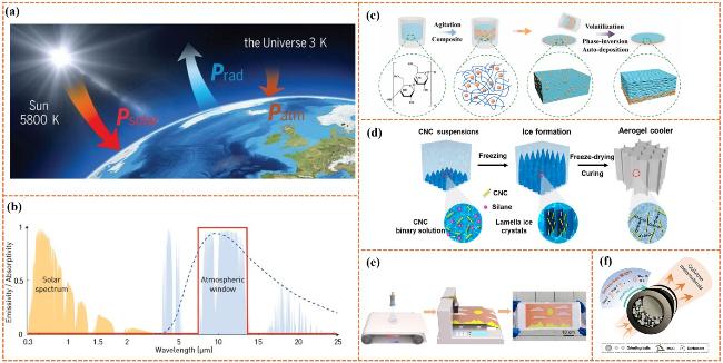
图1 辐射制冷原理及多孔材料制备示意图:(a)发生在地球表面的辐射热流示意图[3];(b)太阳光谱及地面辐射光谱示意图[7];(c)相分离法示意图[51];(d)冰模板法示意图[52];(e)静电纺丝法示意图[53];(f)球磨法示意图[54]Fig.1 Schematic diagram of the principle of radiative cooling and the preparation of porous materials:(a)Schematic diagram of radiant heat flow occurring on the Earth's surface[3]. Copyright 2020 American Association for the Advancement of Science.(b)Solar spectrum and ground radiation spectrum diagram[7]. Copyright 2019 Optica.(c)Diagram of phase separation method[51]. Copyright 2021 Elsevier BV.(d)Ice-templating method diagram[52]. Copyright 2022 American Chemical Society.(e)Diagram of electrospinning[53]. Copyright 2022 Science China Press.(f)Diagram of ball milling[54]. Copyright 2024 Wiley-VCH Verlag |
表2 多孔纤维素基辐射制冷材料不同制备方法的优缺点对比表Table 2 Comparison of preparation methods of porous cellulose based radiative cooling materials |
| Preparation method | Advantages | Disadvantages |
|---|---|---|
| Phase separation[51] | (1)Simple and fast preparation process (2)Tunable pore size | Environmentally unfriendly production process due to the common use of organic solvents |
| Ice-templating[52] | (1)Macro-porous materials with ordered architecture (2)Environmentally friendly production process | (1)Complex fabrication process (2)Difficulty in the large-scale manufacture |
| Electrospinning[53] | (1)Large specific surface area (2)Adjustable pore size (3)Easy surface modification | (1)Relatively high preparation cost (2)Environmentally unfriendly production process due to the common use of organic solvents |
| Ball milling[54] | (1)Simple and fast preparation process (2)High yield | High energy consumption |
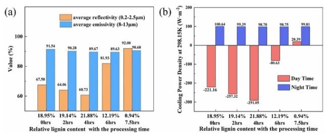
图3 木质素含量与去木质化木材热辐射性能关系示意图[62] :(a)不同木质素含量去木质化木材的光谱特性;(b)不同木质素含量去木质化木材的辐射制冷功率密度Fig.3 Relationship between lignin content and thermal radiative properties of delignified wood[62].(a)Spectral properties of delignified wood with different lignin contents;(b)Radiative cooling power density of delignified wood with different lignin contents. Copyright 2023 Elsevier |
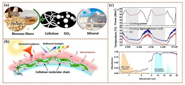
图4 使用农业残渣构建辐射制冷材料的过程及材料结构示意图[65]:(a)制备过程示意图;(b)材料表面辐射制冷机理示意图;(c)材料辐射制冷能力示意图Fig.4 Process and structure diagram of radiative cooling materials constructed with agricultural residues[65].(a)Preparation process diagram;(b)Schematic diagram of material surface radiative cooling mechanism;(c)Schematic diagram of material radiative cooling capacity. Copyright 2021 American Chemical Society |
表3 CNC与CNF特性差异表Table 3 Comparative characteristics between CNC and CNF |
| Name | Preparation method | Morphological characteristics | Feature | ||
|---|---|---|---|---|---|
| CNC | Direct mechanical treatment or pretreatment(e.g. enzymatic hydrolysis,chemical pretreatment)+mechanical treatment | Rigid and rod-like shape; | (1)High crystallinity; (2)High Young's modulus; (3)Low coefficient of thermal expansion; (4)Liquid crystalline properties; (5)High cost & Low yields | ||
| Diameter | 3~50 nm | ||||
| Length | 100~250 nm | Plant-derived cellulose | |||
| 100 nm to a few microns | Tunicin | ||||
| CNF | Acid hydrolysis | Flexible and entangled network consisting of many long cellulose nanofibrils; | (1)Lower crystallinity compared with CNC; (2)Superior mechanical toughness; (3)Low cost & High yields | ||
| Diameter | 3~100 nm | ||||
| Length | >100 nm,up to several microns | ||||
CNC: Cellulose nanocrystals,also known as nanocrystalline cellulose(NCC)or cellulose nanocrystalline whiskers(CNW); CNF: Cellulose nanofibers,also known as microfibrillated cellulose(MFC)or nanofibrillated cellulose(NFC). |
表4 天然纤维素基辐射制冷材料的辐射制冷性能对比表Table 4 Comparison of radiative cooling performance of natural cellulose based radiative cooling materials |
| Natural cellulose base | Example | Solar reflectivity(%) | Mid-infrared emissivity(%) | Solar power intensity (W/m2) | Daytime radiative cooling power (W/m2) | Sub-ambient temperature drop(℃) |
|---|---|---|---|---|---|---|
| Wood fibers | Cooling wood[60] | n.a. | >90 | n.a. | 16 | >4 |
| Delignified wood(0.94 wt%)[62] | 92 | 90.68 | n.a. | 20.39 | 2.60 | |
| Ion-dyed cooling cellulose bulk[63] | n.a. | ~90 | n.a. | 27.6 ~43.3 | 2.2~3.9 | |
| Bamboo fibers | Cooling bamboo[64] | n.a. | >90 | n.a. | n.a. | 3 |
| Biomass fibers | Cooling lignocellulosic bulk[65] | ∼94 | >90 | 900 | 65.3 | 6 |
| Dual-mode TMS material[66] | ∼95 | >90 | n.a. | 52.5 | 6 | |
| Cellulose pulps | Cooling pulp[67] | 89.8 | 93.6 | 1000 | 33.2 | 1~2 |
| Cooling paper[68] | 94 | 95 | 970 | n.a. | 5.4 | |
| ZnO nanorods @cellulose[69] | 93.6 | 84.1 | n.a. | n.a. | 5 | |
| ZnO-DF[70] | 81 | 93 | 1000 | n.a. | 5.6 | |
| CNC | Cellulose cooler[75] | >96 | >90 | 640 | n.a. | 6.6 |
| CNC/GLU[76] | >95 | >80 | n.a. | n.a. | 9 | |
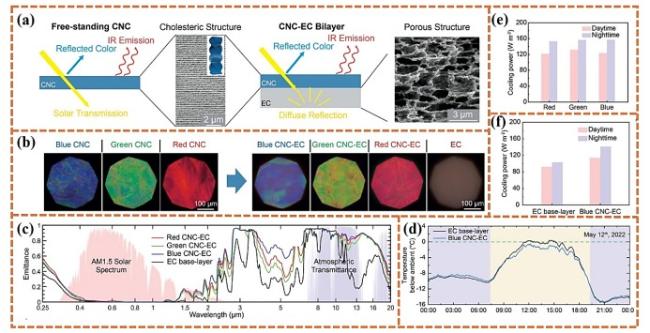
| CNC-EC[78] | 97 | >90 | 900 | <120 | 1.4 | |
| CNWs/ZnO[79] | 97 | 92.5 | 1000 | n.a. | 6.9 | |
| CAG[81] | 97.4 | 94 | 640 | n.a. | 10.5 | |
| CNF | CNF-SiO2[59] | >95 | >90 | n.a. | n.a. | 23 |
| Cellulosic foam[82] | 96.5 | 94 | n.a. | n.a. | 7.5 | |
| CNF/SA@LiCl [83] | 97 | 91 | n.a. | n.a. | 9.3 |
n.a.: not available |
表5 两种厚度的CA膜在太阳光谱和中红外光谱范围内的吸收率对比表Table 5 Comparison of absorption rates of CA films of two thicknesses in the solar spectrum and mid-infrared spectrum |
| Name | Thickness(μm) | Solar absorptivity(%) | Mid-infrared emissivity(%) |
|---|---|---|---|
| CA thin film | 30.0 | 5.2 | 87.9 |
| CA thick film | 300.0 | 5.0 | 93.6 |
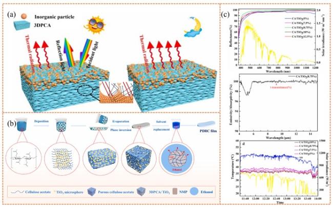
图6 无机粒子-3DPCA薄膜举例示意图:(a)薄膜的结构特征和其在白天和夜间的PRC机理[51];(b)相分离法制备3DPCA/TiO2膜示意图;(c)TiO2掺杂量与3DPCA/TiO2膜辐射制冷性能关系图[91]Fig.6 Schematic illustration of inorganic particle-3DPCA film:(a)Structural characteristics of thin films and their PRC mechanism during day and night[51]. Copyright 2021 Elsevier BV;(b)Schematic diagram of preparation of 3DPCA/TiO2 films by phase separation;(c)Relationship between TiO2 doping amount and radiative cooling performance of 3DPCA/TiO2 film[91]. Copyright 2021 Elsevier. |
表6 纤维素衍生物基辐射制冷材料的辐射制冷性能对比表Table 6 Comparison of radiative cooling performance of the radiative cooling materials based on cellulose derivatives |
| Cellulose derivatives base | Example | Solar reflectivity(%) | Mid-infrared emissivity(%) | Solar power intensity(W/m2) | Daytime radiative cooling power(W/m2) | Sub-ambient temperature drop (℃) |
|---|---|---|---|---|---|---|
| EC | EC/BaSO4[85] | 98.6 | 98.1 | 920 | ≤125.8 | 2.5 |
| CA | Al2O3-CA[87] | 80.1 | 97 | 800 | n.a. | 1.9∼3.3(Fabric) |
| Dual-mode CA@Al2O3/MWCNTs[88] | 92.12 | 83.22 | 1000 | 83.22 | 83.22 | |
| Dual-mode CA/EC/CB[89] | 96.3 | 95.4 | 873 | 115.4 | 8.5 | |
| CA thick film[56] | 95 | 93.6 | n.a. | n.a. | 4.6 | |
| 3DPCA/SiO2[51] | 96 | 95 | 900 | n.a. | 6.2 | |
| 3DPCA/TiO2(8.75 wt%)[91] | 97 | 96 | 897 | n.a. | 10 | |
| 3DPCA/Si-Al[92] | 98 | 83 | 1600 | n.a. | 6.56 | |
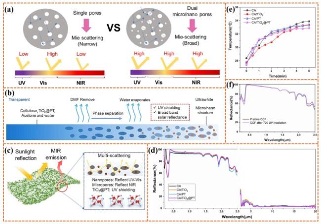
| CA/TiO2@PT[93] | 97.6 | 95 | n.a. | n.a. | 6.5 | |
| CA/CaSiO3[94] | 97.3 | 97.2 | 803~885 | 90.7 | 7.3 | |
| CA/CsPbX3 film[53] | 82~89 | 95 | >740 | 25.6~51.7 | 2.2∼5.4 | |
| CA/TPU[95] | 97.26 | 97.22 | 1550 | n.a. | 9.2 |
n.a.: not available |
表7 细菌纤维素基日间辐射制冷材料的辐射制冷性能对比表Table 7 Comparison of radiative cooling performance of bacterial cellulose based radiative cooling materials |
| Nanocellulose base | Example | Solar reflectivity (%) | Mid-infrared emissivity(%) | Solar power intensity (W/m2) | Daytime radiative cooling power (W/m2) | Sub-ambient temperature drop(℃) |
|---|---|---|---|---|---|---|
| BC | BC/PVA[96] | 98.8 | 86 | 1000 | n.a. | 16.4 |
| Bio-RC[97] | 95.3 | 93.4 | 647 | n.a. | 3.7 | |
| J-BC[98] | 98.1 | 93.6 | 736 | n.a. | 3.8 | |
| M-BC/BaSO4[99] | 97.75 | 95.74 | n.a. | n.a. | 10.4 | |
| M-BC/BaSO4-14[100] | 95.6 | 98.1 | 755.4 | n.a. | 6.64 | |
| 955.35 | n.a. | 8.49 |
n.a.: not available |
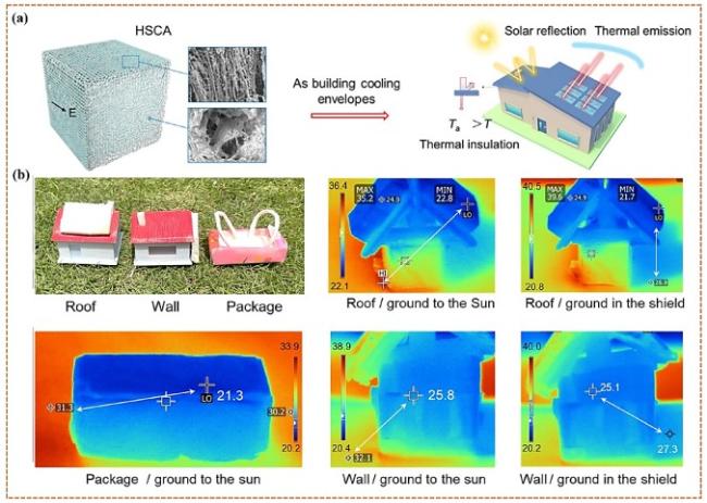
图8 日间辐射制冷技术在建筑节能中的应用[106]:(a)HSCA示意图;(b)太阳光下疏水HSCA建筑围护结构和包装箱的光学图像和红外图像Fig.8 Application of daytime radiative cooling technology in building energy conservation:(a)schematic of HSCA;(b)Optical and infrared images of hydrophobic HSCA building envelope and packing box under sunlight[106],Copyright 2023 American Chemical Society |
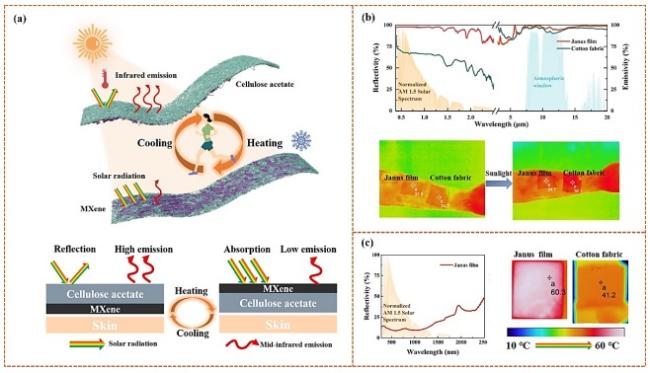
图9 Janus膜在人体热管理领域的应用示意图[113]:(a)Janus膜原理图;(b)制冷模式下Janus膜的太阳反射率和中红外发射率示意图和红外图像;(c)加热模式下Janus膜的太阳反射率示意图和红外图像Fig.9 Schematic diagram of application of Janus film in the field of personal thermal management:(a)janus film schematic;(b)Schematic and infrared images of solar reflectivity and mid-infrared emissivity of Janus film in cooling mode;(c)solar reflectivity schematic and infrared image of Janus film in heating mode[113],Copyright 2023 Elsevier |
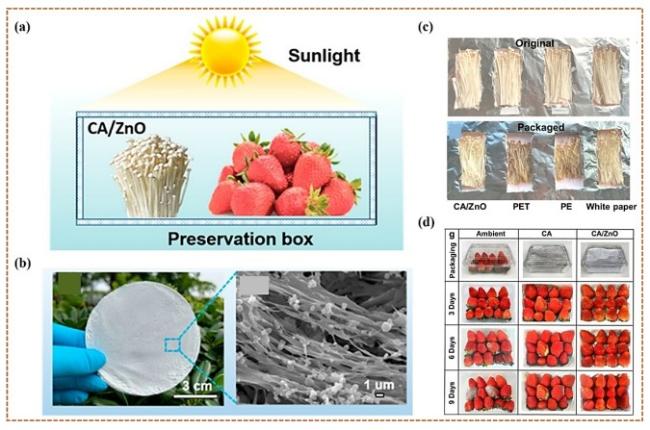
图10 辐射制冷技术在食品保鲜领域的应用示意图[23]:(a)工作原理图;(b)CA/ZnO薄膜结构示意图;(c)金针菇状态对比图;(d)草莓状态对比图Fig. 10 Schematic diagram of application of radiative cooling technology in the field of food preservation:(a)working principle diagram;(b)structure diagram of CA/ZnO film;(c)state comparison of flammulina velutipes;(d)strawberry state comparison diagram[23],Copyright 2023 American Chemical Society |
| [1] |
|
| [2] |
|
| [3] |
|
| [4] |
|
| [5] |
|
| [6] |
|
| [7] |
|
| [8] |
|
| [9] |
|
| [10] |
|
| [11] |
|
| [12] |
|
| [13] |
|
| [14] |
|
| [15] |
|
| [16] |
|
| [17] |
|
| [18] |
|
| [19] |
|
| [20] |
|
| [21] |
|
| [22] |
|
| [23] |
|
| [24] |
(郭晨玥, 潘浩丹, 徐琪皓, 王佳云, 盛茗峰, 赵东亮. 制冷学报, 2022, 43(3): 1.).
|
| [25] |
|
| [26] |
|
| [27] |
|
| [28] |
|
| [29] |
|
| [30] |
|
| [31] |
|
| [32] |
|
| [33] |
|
| [34] |
|
| [35] |
|
| [36] |
|
| [37] |
|
| [38] |
|
| [39] |
|
| [40] |
|
| [41] |
|
| [42] |
|
| [43] |
|
| [44] |
|
| [45] |
|
| [46] |
|
| [47] |
(蔡晨阳, 丁春香, 武小丹, 陈溢. 复合材料学报, 2024, 41(11): 5800.).
|
| [48] |
(张奇, 李晓东, 王文雯, 刘晓. 储能科学与技术, 2023, 12(5): 1427.).
|
| [49] |
|
| [50] |
|
| [51] |
|
| [52] |
|
| [53] |
|
| [54] |
|
| [55] |
|
| [56] |
|
| [57] |
|
| [58] |
|
| [59] |
|
| [60] |
|
| [61] |
|
| [62] |
|
| [63] |
|
| [64] |
|
| [65] |
|
| [66] |
|
| [67] |
|
| [68] |
|
| [69] |
|
| [70] |
|
| [71] |
|
| [72] |
|
| [73] |
|
| [74] |
|
| [75] |
|
| [76] |
|
| [77] |
|
| [78] |
|
| [79] |
|
| [80] |
|
| [81] |
|
| [82] |
|
| [83] |
|
| [84] |
|
| [85] |
|
| [86] |
|
| [87] |
|
| [88] |
|
| [89] |
|
| [90] |
|
| [91] |
|
| [92] |
|
| [93] |
|
| [94] |
|
| [95] |
|
| [96] |
|
| [97] |
|
| [98] |
|
| [99] |
|
| [100] |
|
| [101] |
|
| [102] |
|
| [103] |
|
| [104] |
|
| [105] |
|
| [106] |
|
| [107] |
|
| [108] |
|
| [109] |
|
| [110] |
|
| [111] |
|
| [112] |
|
| [113] |
|
| [114] |
|
| [115] |
|
| [116] |
|
| [117] |
|
/
| 〈 |
|
〉 |