
The Review on Application and Catalytic Mechanism of Transition Metal Catalysts in Li-S Batteries
Received date: 2024-07-13
Revised date: 2024-10-16
Online published: 2025-04-30
Supported by
National Natural Science Foundation of China(52172097)
New Energy Material Innovation Consortium Projects of Yunnan Province(202302AB080018)
Li-S batteries have great application prospects because of their extremely high capacity and energy density. However,the instability and insulation of polysulfides(LiPSs)seriously hinder their further application. In order to solve the problem of slow reaction kinetics in Li-S batteries,it is urgent to explore efficient catalysts to accelerate the sulfur redox. In the case,transition metals with unique and excellent catalytic properties are considered as potential catalysts for Li-S battery. However,differences in the structure and properties of transition metals will lead to different catalytic mechanisms. Therefore,this work divides five types of transition metals(ferrous metals,conventional non-ferrous metals,precious metals,rare refractory metals,and rare earth metals)based on metal characteristics. Then,the catalytic mechanisms of transition metal catalysts were analyzed,including adsorption,accelerating electron transfer,reducing activation energy and co-catalysis. Besides,the research progress of various metals used in Li-S batteries was reviewed,and the catalytic mechanisms of different types of metals were clarified. Four optimization strategies were proposed: nanostructured design,doping-modification,alloying and external cladding,in order to provide certain references for the design of Li-S battery catalysts.
1 Introduction
2 Catalytic mechanism and functionality of transition metal catalysts
2.1 Catalytic mechanism
2.2 Functionality
3 The application of transition metals in lithium sulfur batteries
3.1 Ferrous metal
3.2 Non-ferrous metal
3.3 Noble metal
3.4 Rare refractory metal
3.5 Rare earth metal
4 Challenges and optimization strategies of transition metal catalysts
5 Conclusion and outlook
Xin Chen , Jingzhao Wang , Xiangming Cui , Mi Zhou , Jianan Wang , Wei Yan . The Review on Application and Catalytic Mechanism of Transition Metal Catalysts in Li-S Batteries[J]. Progress in Chemistry, 2025 , 37(5) : 758 -774 . DOI: 10.7536/PC240713
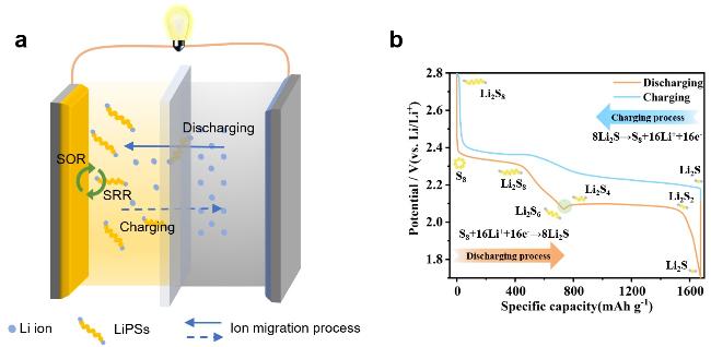
图1 (a)锂硫电池充放电机理示意图;(b)典型的锂硫电池充放电曲线(放电平台: S8→Li2S6(2.4~2.06 V),Li2S6→Li2S(2.06~1.8 V);充电平台:Li2S→Li2S8(2.4~2.7 V))Fig.1 (a)Schematic diagram of charging and discharging mechanism of Li-S battery.(b)Typical lithium-sulfur battery charge and discharge curve(discharge platform: S8→Li2S6(2.4~2.06 V),Li2S6→Li2S(2.06~1.8 V); charging platform: Li2S→Li2S8(2.4~2.7 V)) |
表1 过渡金属分类表Table 1 Classification table of transition metals |
| Transition Metal Classification | |||||||||||
|---|---|---|---|---|---|---|---|---|---|---|---|
| Ferrous metal | Fe | Mn | Cr | ||||||||
| Non-ferrous metal | Ti | Co | Ni | Cu | Zn | Cd | |||||
| Noble metal | Au | Ag | Ru | Os | Rh | Ir | Pd | Pt | |||
| Rare refractory metal | W | Mo | Ta | Nb | V | Zr | Re | Hf | |||
| Rare earth metal | Light | La | Ce | Pr | Nd | Pm | Sm | Eu | |||
| Heavy | Gd | Tb | Dy | Ho | Er | Tm | Yb | Lu | Se | Y | |
| Radioactive metal | Rf Db Sg Bh Hs Mt Ds Rg Ac Th Pa U Np Pu Am Cm Bk Cf Es Fm Md No Lr | ||||||||||
表2 过渡金属催化剂应用于锂硫电池中的相关研究及电池性能汇总Table 2 A summary of research on the application and battery performance of transition metal catalysts to lithium sulfur batteries |
| Type of Metals | Cathodes | Discharge capacity | Stability(decay rate %per cycle) | Ref |
|---|---|---|---|---|
| Ferrous metals | SA-Fe/VN@NMC | 1216.8 mAh·g-1 at 0.2 C | 700 cycles at 1 C(0.024%) | 50 |
| FeNi@NC | 1378.8 mAh·g-1 at 0.1 C | 500 cycles at 1 C(0.11%) | 51 | |
| Mn-N-C | 1596 mAh·g-1 at 0.1 C | 1000 cycles at 1 C(0.045%) | 55 | |
| STO@Fe | 1428 mAh·g-1 at 0.2 C | 400 cycles at 1 C(0.061%) | 52 | |
| S@Mn-CCs | 1420 mAh·g-1 at 0.2 C | 200 cycles at 1 C | 53 | |
| Fe-N3C2-C | 1200 mAh·g-1 at 0.2 C | 1000 cycles at 2 C(0.053%) | 49 | |
| Non-ferrous metals | Cu/mTiO2-NC | 1150 mAh·g-1 at 0.2 C | 600 cycles at 0.5 C(0.09%) | 63 |
| SANi-N4-O/NC | 1321 mAh·g-1 at 0.2 C | 1000 cycles at 5 C(0.043%) | 73 | |
| Co-N-C | 1250 mAh·g-1 at 0.25 C | 1000 cycles at 0.5 C(0.04%) | 47 | |
| Ni-NC | 1489 mAh·g-1 at 0.2 C | 700 cycles at 1 C(0.032%) | 70 | |
| Ni-ZIF-8-MA | 1232.4 mAh·g-1 at 0.3 C | 350 cycles at 0.5 C(0.095%) | 69 | |
| Zn-CoN4O2/CN | 1544.1 mAh·g-1 at 0.1 C | 1000 cycles at 6 C(0.05%) | 68 | |
| sGNC-S | 829.3 mAh·g-1 at 0.5 C | 200 cycles at 1 C(0.155%) | 71 | |
| Ni/PCMS | 1426.7 mAh·g-1 at 0.1 C | 800 cycles at 1 C(0.078%) | 72 | |
| Co-NiS2@CNF/CNT | 1450 mAh·g-1 at 0.2 C | 3000 cycles at 5 C(0.018%) | 64 | |
| SA-ZnN4-NC | 1225.3 mAh·g-1 at 0.2 C | 500 cycles at 1 C(0.033%) | 74 | |
| Co-3DC-rGO/PP | 1332.3 mAh·g-1 at 0.1 C | 500 cycles at 1 C(0.043%) | 67 | |
| SA-Cu@NCNF | 1136.4 mAh·g-1 at 0.2 C | 500 cycles at 5 C(0.038%) | 62 | |
| CNTs/Co | 1242.5 mAh·g-1 at 0.2 C | 300 cycles at 1 C(0.066%) | 65 | |
| MC-Cu-S | 1050 mAh·g-1 at 100 mA·g-1 | 550 cycles at 100 mA·g-1(0.095%) | 61 | |
| Noble metals | PdNP-CITCF | 907 mAh·g-1 at 1 C | 500 cycles at 1 C(0.10%) | 76 |
| Pd/OMC | 1527 mAh·g-1 at 0.1 C | 500 cycles at 2 C(0.031%) | 34 | |
| TiO2-Ru | 1170 mAh·g-1 at 0.2 C | 600 cycles at 2 C(0.015%) | 77 | |
| CuIr/NC | 1288 mAh·g-1 at 0.2 C | 1000 cycles at 1 C(0.033%) | 46 | |
| Pt/Ti2C/S | 890 mAh·g-1 at 0.2 C | - | 37 | |
| Pd@NDHPC@SiO2 | 1086 mAh·g-1 at 0.2 C | - | 38 | |
| Pd@HCS | 1306 mAh·g-1 at 0.2 C | 400 cycles at 1 C(0.068%) | 38 | |
| Rare refractory metals | Mo/NG | 1543.5 mAh·g-1 at 0.2 C | 500 cycles at 1 C(0.048%) | 80 |
| MoS2-Co9S8/rGO | 1382.5 mAh·g-1 at 0.1 C | 600 cycles at 3 C(0.06%) | 79 | |
| Mo@N-G | 1359 mAh·g-1 at 0.2 C | 500 cycles at 3 C(0.05%) | 78 | |
| Mo-N-C | 743.9 mAh·g-1 at 5 C | 550 cycles at 2 C(0.018%) | 11 | |
| Rare earth metals | Ce-UiO-66-NH2 | 1366.3 mAh·g-1 at 0.2 C | 300 cycles at 1 C(0.09%) | 83 |
| La@PCNFs | 976 mAh·g-1 at 1 C | 1000 cycles at 5 C(0.05%) | 82 | |
| Ce-MOF-2/CNT | 993.5mAh·g-1 at 0.1 C | 800 cycles at 1 C(0.022%) | 81 |
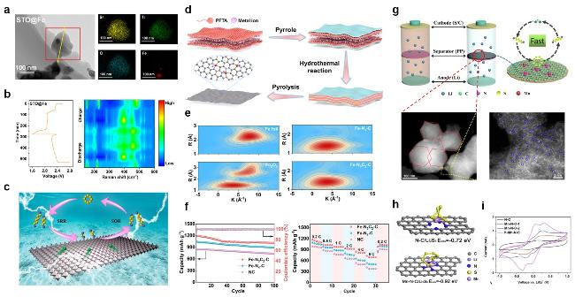
图3 (a)异质结构材料STO@Fe的TEM图像,Sr、Ti、O、Fe元素对应的mapping图;(b)STO@Fe的时间电压曲线和原位拉曼等值线图;(c)SRR和SOR反应的催化机理示意图[52];(d)Fe-N3C2-C的合成示意图;(e)Fe-N3C2-C、Fe-N4-C、Fe2O3和Fe箔的WT图;(f)含Fe-N3C2-C、Fe-N4-C、NC的Li-S电池在0.5 C下的循环性能和倍率性能[49];(g)h-Mn-N-C改性隔膜的工作机理示意图和不同倍率下h-Mn-N-C催化剂的HAADF-STEM图像,(h)h-Mn-N-C对Li2S6的吸附能和(i)不同催化剂的CV曲线[55]Fig. 3 (a)TEM images of the heterostructure material STO@Fe. Corresponding element mappings of Sr,Ti,O,Fe elements.(b)Time-voltage curves and in situ Raman contour plots of STO@Fe.(c)Schematic diagram of the catalytic mechanism for the SRR and SOR reactions[52].(d)Schematic illustration of the synthesis of Fe-N3C2-C.(e)WT plots of Fe-N3C2-C,Fe-N4-C,Fe2O3,and Fe foil.(f)Cycling performance at 0.5 C and rate performance of Li-S batteries with Fe-N3C2-C,Fe-N4-C,and NC[49].(g)Schematic illustration showing the working mechanism of h-Mn-N-C modified separator and HAADF-STEM images of h-Mn-N-C catalyst at different magnification.(h)Adsorption energy of H-Mn-N-C for Li2S6 and(i)CV curves of different catalysts[55] |
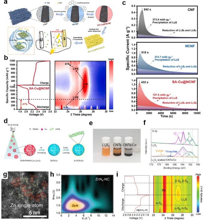
图4 (a)SA-Cu@NCNF作为Li-S电池载硫体的合成过程示意图和Li2S的沉积/解离过程;(b)SA-Cu@NCNF/S的充放电曲线及相应的原位XRD等高线图;(c)CNF、NCNF和SA-Cu@NCNF电极Li2S的恒电位沉积曲线[62];(d)S-CNTs/Co的合成过程示意图;(e)CNTs和CNTs/Co对Li2S6的静态吸附实验;(f)CNTs/Co吸附的Li2S6和原始Li2S6的S 2p高分辨率XPS光谱[66];(g)ZnN4-NC的ACTEM;(h)ZnN4-NC的小波变换;(i)S@ZnN4-NC阴极在0.1 C时的原位XRD图谱[74]Fig. 4 (a)Schematic illustration of the synthetic procedures of SA-Cu@NCNF as sulfur hosts for Li-S batteries and facile Li2S deposition/dissociation.(b)Charge/discharge profiles and the corresponding in-situ XRD contour plots of SA-Cu@NCNF/S.(c)Potentiostatic Li2S deposition curves of CNF,NCNF,and SA-Cu@NCNF electrodes[62].(d)Schematic illustration on the synthesis process of S-CNTs/Co.(e)Visualized adsorption experiment of CNTs and CNTs/Co toward Li2S6.(f)S 2p high-resolution XPS spectra of pristine Li2S6 and Li2S6 adsorbed by CNTs/Co[66].(g)ACTEM of ZnN4-NC.(h)Wavelet transform of ZnN4-NC.(i)in situ XRD patterns of S@ZnN4-NC cathode at 0.1 C[74] |
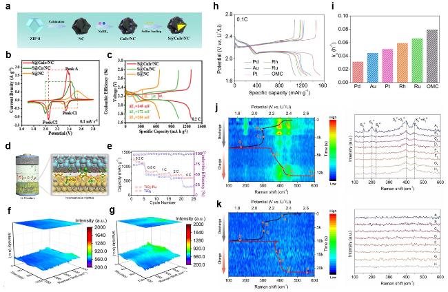
图5 (a)S@CuIr/NC样品的合成示意图;(b)S@CuIr/NC、S@Cu/NC和S@NC电极在0.1 mV·s-1时的CV曲线;(c)S@CuIr/NC、S@Cu/NC和S @NC电极在0.2 C时的恒流充放电曲线[46];(d)Li-S电池中TiO2/Ru非均相界面上LiPSs的调节效应示意图;(e)TiO2-Ru@S和TiO2@S电极在0.2~4 C时的速率性能;(f,g)基于TiO2-Ru@S电极的Li-S电池在(f)放电过程和(g)充电过程中的原位拉曼光谱[77];(h)Pd/OMC、Au/OMC、Pt/OMC、Rh/OMC、Ru/OMC和OMC催化电池在0.1 C电流密度下的恒流充放电曲线;(i)Li-S电池的穿梭常数[34]Fig. 5 (a)Schematic diagram of the synthesis of the S@CuIr/NC sample.(b)CV profiles of the S@CuIr/NC,S@Cu/NC,and S@NC electrodes at 0.1 mV·s-1.(c)Galvanostatic charge/discharge profiles with various cathodes of the S@CuIr/NC,S@Cu/NC,and S@NC electrodes at 0.2 C[46].(d)Regulation effect of LiPSs at TiO2/Ru heterogeneous interface in a Li-S battery.(e)Rate performance of TiO2-Ru@S and TiO2@S cathodes from 0.2 to 4 C,(f-g)In situ Raman spectroscopy of Li-S cells based on TiO2-Ru@S cathode during the(f)discharge and(g)charge process[77].(h)Galvanostatic charge/discharge profiles at a current density of 0.1 C for Pd/OMC,Au/OMC,Pt/OMC,Rh/OMC,Ru/OMC,and OMC catalyzed batteries.(i)The shuttle constant of Li-S cells[34] |
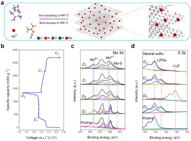
图6 (a)Mo@N-G合成示意图;对Mo@N-G/S电极在电池循环中的非原位XPS研究,(b)不同充放电状态下Mo@N-G/S电极,(c)不同充放电阶段下Mo 3d光谱,(d)不同充放电阶段下S 2p光谱[78]Fig.6 (a)Schematic of the synthesis for the Mo@N-G. Ex situ XPS study of cycled Mo@N-G/S electrodes;(b)Mo@N-G/S electrode at different charging/ discharging states;(c)Mo 3d spectra,and(d)S 2p spectra at different states[78] |
| [1] |
|
| [2] |
|
| [3] |
|
| [4] |
|
| [5] |
|
| [6] |
|
| [7] |
|
| [8] |
|
| [9] |
|
| [10] |
|
| [11] |
|
| [12] |
|
| [13] |
|
| [14] |
|
| [15] |
|
| [16] |
|
| [17] |
|
| [18] |
|
| [19] |
|
| [20] |
|
| [21] |
|
| [22] |
|
| [23] |
|
| [24] |
|
| [25] |
|
| [26] |
|
| [27] |
|
| [28] |
|
| [29] |
|
| [30] |
|
| [31] |
|
| [32] |
|
| [33] |
|
| [34] |
|
| [35] |
|
| [36] |
|
| [37] |
|
| [38] |
|
| [39] |
|
| [40] |
|
| [41] |
|
| [42] |
|
| [43] |
|
| [44] |
|
| [45] |
|
| [46] |
|
| [47] |
|
| [48] |
|
| [49] |
|
| [50] |
|
| [51] |
|
| [52] |
|
| [53] |
|
| [54] |
|
| [55] |
|
| [56] |
|
| [57] |
|
| [58] |
|
| [59] |
|
| [60] |
|
| [61] |
|
| [62] |
|
| [63] |
|
| [64] |
|
| [65] |
|
| [66] |
|
| [67] |
|
| [68] |
|
| [69] |
|
| [70] |
|
| [71] |
|
| [72] |
|
| [73] |
|
| [74] |
|
| [75] |
|
| [76] |
|
| [77] |
|
| [78] |
|
| [79] |
|
| [80] |
|
| [81] |
|
| [82] |
|
| [83] |
|
| [84] |
|
| [85] |
|
| [86] |
|
| [87] |
|
| [88] |
|
| [89] |
|
| [90] |
|
| [91] |
|
| [92] |
|
| [93] |
|
| [94] |
|
| [95] |
|
| [96] |
|
/
| 〈 |
|
〉 |