Home Journals Progress in Chemistry
Progress in Chemistry

Abbreviation (ISO4): Prog Chem      Editor in chief: Jincai ZHAO

About  /  Aim & scope  /  Editorial board  /  Indexed  /  Contact  / 
Review

Conductive Phase Change Materials (PCMs) for Electro-to-Thermal Energy Conversion, Storage and Utilization

  • Jiang Haoyang 2 ,
  • Xiong Feng 1 ,
  • Qin Mulin 1 ,
  • Gao Song 1 ,
  • He Liuruyi 2 ,
  • Zou Ruqiang , 1, *
Expand
  • 1. School of Materials Science and Engineering, Peking University, Beijing 100871, China
  • 2. Army Logistics Academy of PLA, Chongqing 401331, China
* Corresponding author e-mail:

These authors contributed equally to this work.

Received date: 2022-09-21

  Revised date: 2022-11-05

  Online published: 2023-02-20

Supported by

Youth Scientific Research Fund of Army Logistics Academy of PLA China(LQ-QN-202117)

National Key Research and Development Program of China(2020YFA0210701)

Abstract

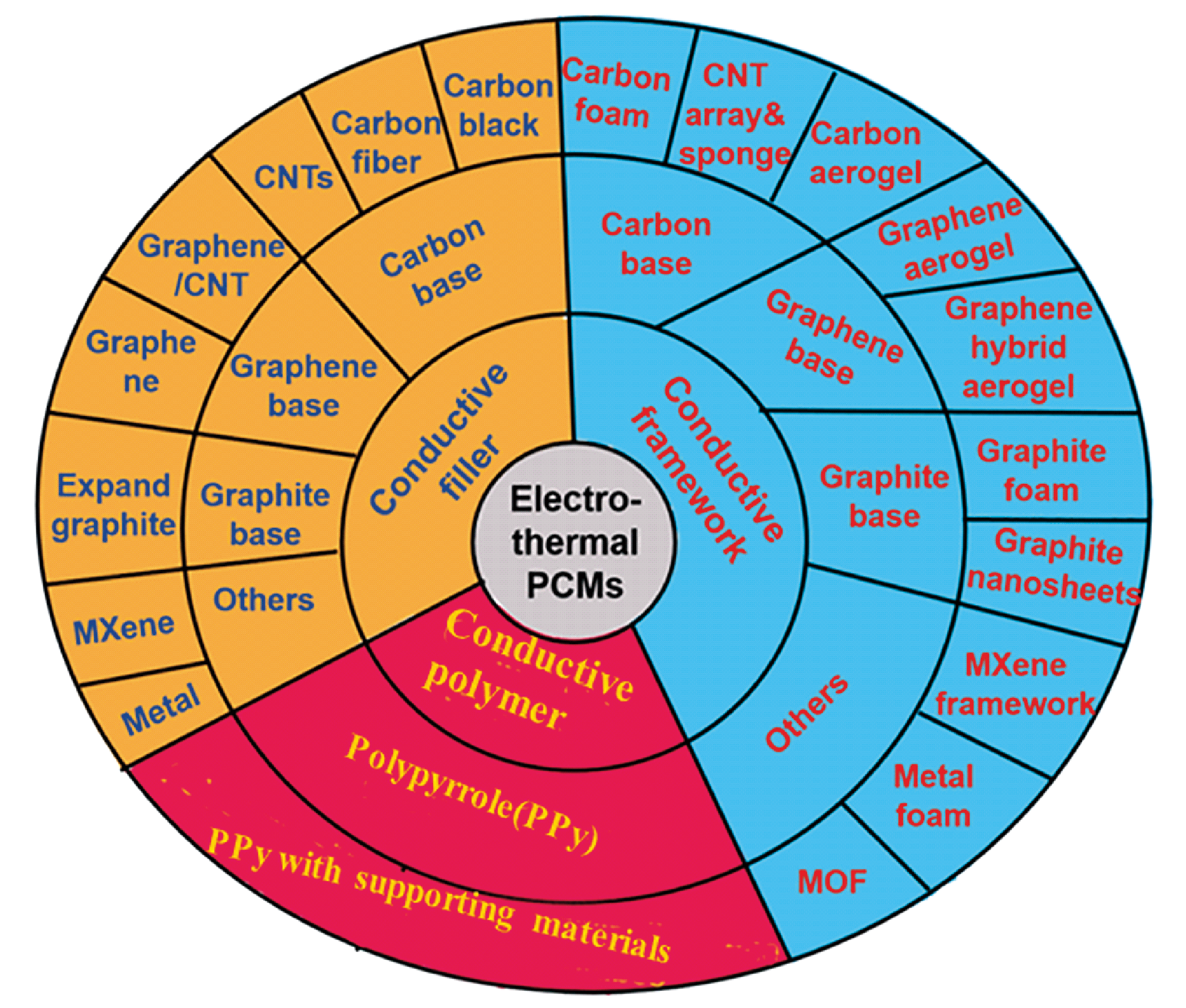
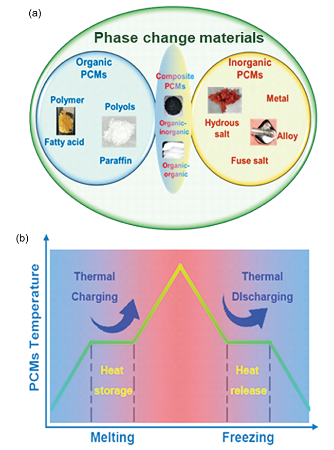
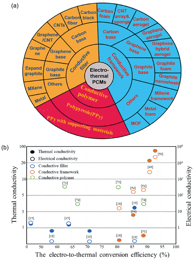
As the largest supply end and demand end in daily production respectively, the conversion, storage and utilization of electric energy and thermal energy play an important role in energy systems. Therefore, it is of great significance to develop high-efficiency materials for electro-thermal conversion and storage, especially facing today’s energy crises, environmental pollution and extreme climates. Among heat storage materials, phase change materials (PCMs) own unique advantages because of their high latent heat storage density and constant temperature during heat absorption and release. However, the low intrinsic conductivity of most PCMs does not match the large power requirements of current energy storage systems. This issue can be effectively improved by combining PCMs with conductive materials to obtain electrically heatable PCM composites. In this article, the latest research progress of electro-thermal conversion PCMs from three aspects of the functional mechanism, affecting factors and applications are systematically reviewed. Moreover, PCMs composited with conductive fillers, conductive framework and serving as conductive polymers are summarized and compared critically. Finally, this article points out the potential direction of future research and emphasizes the key points of this field.

Cite this article

Jiang Haoyang , Xiong Feng , Qin Mulin , Gao Song , He Liuruyi , Zou Ruqiang . Conductive Phase Change Materials (PCMs) for Electro-to-Thermal Energy Conversion, Storage and Utilization[J]. Progress in Chemistry, 2023 , 35(3) : 360 -374 . DOI: 10.7536/PC220922

Contents

1 Introduction
2 Electrothermal conversion mechanism of phase change composites
3 Functional phase change composites for electrical energy conversion,storage and utilization
3.1 Phase change composites doped with conductive fillers
3.2 Phase change composites supported by conductive framework
3.3 Phase change composites composed of conductive polymer
4 Application of electrothermal phase change composites
5 Conclusion and outlook

1 Introduction

With the rapid growth of population and economy, the global demand for energy is increasing, and the research on renewable energy (solar energy, wind energy, hydropower, geothermal energy, biomass energy, etc.) Has become the focus in recent years[1]. In the process of renewable energy utilization, it is often converted and stored according to actual needs[2]. Heat is one of the most abundant forms of energy, and electricity is one of the most convenient. Both are the basis of many domestic and industrial applications, and 90% of the world's energy consumption is linked to heat[3]. By converting all kinds of energy into heat and storing them, it can not only reduce the mismatch between energy supply and demand, but also improve the performance and reliability of the energy system, which is an important means of energy conservation[4].
Thermal energy storage system stores and releases heat energy through temperature increase and decrease, phase change or chemical reaction, including sensible heat storage, latent heat storage and thermochemical energy storage. Sensible heat storage is mainly used to store heat energy through the increase and decrease of temperature, which has low energy storage density, large heat loss and low efficiency. Latent heat storage is carried out through the phase change of internal materials, which can store a large amount of heat energy in a narrow temperature range, and its heat storage density is nearly four times higher than that of sensible heat storage under the same temperature range and the same volume/mass of storage materials[5]. Thermochemical energy storage is carried out by reversible chemical reactions, and the energy storage density is the largest[6]. At present, sensible heat storage has been developed into commercial applications, latent heat storage is in the transition from laboratory research to commercial applications, and thermochemical storage is still in laboratory research[5]. Therefore, combined with the energy storage density and the maturity of the technology, latent heat storage has unique advantages. Materials that store latent heat through phase change are called phase change materials. The classification and principle are shown in Figure 1[7].
图1 (a)相变材料分类; (b)相变材料热能存储与释放机理

Fig. 1 (a) Classification of phase change materials; (b) mechanism of thermal energy storage and release of PCMs

In the process of latent heat storage, the first step is the conversion and transmission of energy, including photothermal, electrothermal, magnetothermal conversion and heat conduction[8~10][11~13]. As the largest supply side and consumption side in life and production, the conversion, storage and utilization of electricity and heat occupy an important part of the energy system. In the power supply system of all countries in the world, there is a peak-valley problem. The shortage of power during the peak period of power consumption affects production, and the surplus of power during the trough period of power consumption will affect the stability of the system and cause the cost of energy storage. The high efficiency of Joule heat conversion and the high energy density of latent heat storage are fully utilized by converting valley electricity into latent heat for storage and releasing it during peak power consumption for heating, production or thermal power generation, which makes electrothermal phase change materials have unique application value in power peak shaving and heat storage. On the other hand, electrothermal conversion systems are widely used in building temperature control, intelligent fabrics, manned spaceflight, precision instrument temperature control and other fields. The high potential heat value of electrothermal phase change materials while conducting electricity helps to improve their temperature stability and high and low temperature thermal shock resistance. Therefore, the research and development of efficient electrothermal conversion-storage functional materials is of great significance in today's frequent energy, environmental and climate crises. However, the low resistivity (10-12~10-7S/m) of most PCMs limits their application in the field of electrothermal conversion, so it is necessary to improve the conductivity of PCMs by compounding with highly conductive materials[18]. In this paper, the latest research progress of electrothermal phase change materials is reviewed, including the functional mechanism, influencing factors and applications of electrothermal phase change materials.The composite phase change materials with conductive filler, loaded conductive skeleton or conductive polymer polymerization were reviewed and compared, and the future research directions and priorities in this field were prospected.

2 Electrothermal conversion mechanism of phase change materials

In the process of converting electric energy into heat energy and storing it in the phase change material, the energy mainly goes through three steps: electrothermal conversion, heat exchange, and heat storage. The mechanism is shown in Figure 2. First, with the load of voltage, the electrons in the composite phase change material move directionally along the conductive path, that is, the current passes through the phase change material. The moving electrons collide with other molecules or groups to generate Joule heat to realize electrothermal conversion, which can be calculated by Joule's law:[14]
Q = I 2 R t = U I t = ( U 2 / R ) t
Q: Joule heat (J), U: voltage (V), I: current (A), R: resistance (Ω), t: time (s).
图2 电热复合相变材料电热转换机理

Fig. 2 Electrothermal conversion mechanism of electrothermal phase change composites including conductive additives, conductive framework and conductive polymer, respectively

Subsequently, the generated heat energy is mainly transferred to the phase change material through heat conduction. At this time, the temperature of the phase change material rises sharply. At this stage, no phase change occurs, and the heat energy is mainly stored in the form of sensible heat. This part of heat is calculated in the following way:
Q = m C P Δ T
Q: Joule heat (J), m: phase change material mass (kg),CP: specific heat at constant pressure (J/ (kg · K)), ΔT: temperature difference (K).
As the electrothermal conversion continues, the generated heat is stored in the phase change material in the form of latent heat through solid-liquid phase change. At this time, the phase change material begins to melt, and the temperature change amplitude is reduced. Since the material has complete phase change and the temperature change during phase change is very small, the energy density of phase change heat storage is calculated by the following formula:
Q = m Δ H
Q: Joule heat (J), m: mass of PCM (G), ΔH: latent heat of phase change (J/G).
After the phase change, the temperature of the phase change material continues to rise and continues to store the generated heat in the form of sensible heat. When the stored heat energy needs to be utilized, the process is the opposite. First, the temperature drops sharply, and the heat energy is released in the form of sensible heat. Then, the liquid-solid phase change occurs. At this time, the temperature changes slowly, and the heat energy is released in the form of latent heat. After the phase change, the temperature continues to drop and the heat is released through sensible heat.
In this process, the electrothermal conversion efficiency of the material can be obtained by calculating the ratio of the heat stored to the heat generated by the material in the phase change stage, and the calculation formula is as follows:
η = ( m Δ H ) / U I t
M: mass of phase change material (G), ΔH: latent heat of phase change (J/G), UIt: Joule heat generated during phase change time (J).
The electrothermal conversion efficiency is often affected by the type of high conductivity materials, the construction of conductive heat transfer paths, the applied voltage and the heat flow loss. Different types of materials have different abilities to enhance electrical and thermal conductivity, which affects the proportion of phase change materials in composite materials, and directly affects the latent heat and heat storage capacity of phase change. High applied voltage and low heat loss can shorten the phase transition period and improve the electrothermal conversion efficiency, so appropriate heat sealing technology can be used to reduce the diffusion of heat to the environment and further improve the electrothermal conversion efficiency. The structural design of electrothermal composite phase change materials has the most important influence. By coordinating the coupling of material orientation and conductive heat transfer pathways, the collection of electric energy and the transmission of heat energy can be effectively improved, the surface heat enrichment and loss can be reduced, and the electrothermal conversion efficiency can be effectively improved.
It should be noted that there is often a minimum working voltage, when the applied voltage is lower than this voltage, the electrothermal conversion is difficult to reach the phase change temperature required for the phase change of the material, and the heat energy is stored in the phase change material in the form of sensible heat rather than latent heat.

3 Functional composite phase change materials for electric energy conversion, storage and utilization

By introducing the high conductivity material, the conductivity of the phase change material can be effectively improved, and the obtained composite material provides a transmission path for electrons through the internal conductive network,Joule heat is generated by the collision of internal electrons with other molecules or groups, and the heat is absorbed by the phase change material and stored in the form of latent heat, thereby realizing the electrothermal conversion and storage of the composite material. According to the different composite modes of conductive materials, electrothermal phase change materials can be divided into phase change materials doped with conductive fillers, phase change materials loaded with conductive skeletons, and phase change material polymerized with conductive polymers, as shown in Fig. 3 (a).
图3 (a)电热相变材料分类; (b)电热相变材料对比

Fig. 3 (a) Classification of electrothermal phase change composites via different enhancing mechanisms. (b) Comparison of electrothermal phase change composites via different enhancing mechanisms

Compared with the conductive filler doping, the conductive skeleton-loaded composite shows relatively higher electrical conductivity, thermal conductivity and electrothermal conversion efficiency due to the construction and coupling of its internal electrothermal pathways. Conductive polymers exhibit high electrical conductivity, but due to their low thermal conductivity, their applied voltage and electrothermal conversion efficiency are between the two, as shown in Figure 3 (B). The electrothermal conversion ability of electrothermal composite phase change materials is measured by the working voltage and the electrothermal conversion efficiency. How to improve the electrothermal conversion efficiency under the condition of reducing the working voltage as much as possible has important research value in the field of electrothermal conversion.

3.1 Conductive Filler Doped Electrothermal Phase Change Material

In addition to conventional conductive metal materials, the electrothermal phase change materials doped with conductive fillers are mainly carbon materials (carbon black, carbon fiber, carbon nanotube, expanded graphite, graphene, etc.).New conductive materials such as two-dimensional metal nitride (MXene) composite electrothermal phase change materials have also been studied. While improving the electrothermal conversion ability of phase change materials, the effective packaging of phase change materials is also the focus of this part of the research. The addition and encapsulation of conductive fillers tend to reduce the latent heat of phase change of composites, and the dispersion and random arrangement of internal fillers are not conducive to the construction of electrothermal conduction pathways, so the electrothermal phase change materials doped with conductive fillers show lower electrothermal conversion ability and phase change enthalpy as a whole. Conductive fillers such as carbon nanotubes and graphene, which can provide higher electrothermal conversion capability at a low ratio, and fillers such as expanded graphite, which can be encapsulated by simple adsorption and construct electrothermal conversion pathways, often show relatively high electrothermal conversion efficiency, as shown in Table 1 and Figure 3 (B).
表1 导电填料复合电热相变材料性能

Table 1 Properties of conductive filler electrothermal phase change composite

Conductive filler PCMs Filler content
(wt%)
T m a
( ℃)
Latent heat
(J/g)
λW/(m·k) σb
(S/m)
The trigger voltagec (V) ηd
(%)
The working voltage e (V) ref
acetylene black PEG2000·
CaCl2
20 51.48 78.5 1.2 3.3 1.5 29.7 1.5 15
acetylene black PEG2000·
CaCl2
20 51.48 78.5 1.2 3.3 1.5 64.7 2.5 15
carbon
nanofiber
paraffin wax 2 70 - - 0.2 - - - 16
single-wall CNT hexadecyl acrylate - 36.7 52 0.4675 718 - - - 17
multi-wall CNT hexadecyl acrylate - 38 40 0.877 389 - - - 17
CNTs PEG2000-
CaCl2
20 49.72 89.81 0.91 0.01 - 58.3 1.5 18
CNTs PEG2000-
CaCl2
20 49.72 89.81 0.91 0.01 - 70.2 2 18
expanded graphite PEG2000-
CaCl2
6 49.3 107.5 3.73 0.2 2 48.2 2 19
expanded graphite PEG2000-
CaCl2
6 49.3 107.5 3.73 0.2 2 86.9 5 19
expanded graphite Methyl stearate 15 33.4 147 3.6 - 1.4 47 1.4 20
expanded graphite Methyl stearate 15 33.4 147 3.6 - 1.4 72 1.7 20
expanded graphite N-eicosane 15 36.41 199.4 3.56 - 1.9 65.7 2.1 21
expanded graphite N-eicosane 30 36.31 163.5 4.21 - 1.9 42.9 2.1 21
expanded graphite paraffin 20 56.2 120 1.38 5 - - - 22
expanded graphite paraffin 70 43.05 47.76 19.27 4545 - - 4.4 23
graphene Hexadecyl acrylate - 32.7 57 3.957 219 - - 30 24
graphene oxide/CNT PEG1000 22 37.24 110.7 0.45 - 5.8 70 6.6 25
graphene oxide/CNT docosane 3.3 38.1 240.8 - 52.63 - - - 26
graphene/
PANI
PEG20000 - 57.93 115.97 - - - - - 27
CNT/PU/
PDA/
PEDOT:PSS
paraffin wax - 20 106.86 - - - 42.92 3 28
CNT/PU/
PDA/
PEDOT:PSS
paraffin wax - 20 106.86 - - - 91.03 4.2 28
CNT/PU/Ag nanoflower Lauric acid - 46 124.5 0.479 190 - 70.1 20 29
cotton/
stainless steel wire
PEG - 53.53 33.46 0.281 - - - - 30
Ti3C2 MXene
nanosheets
PEG4000 22.5 60 131.2 2.052 10.41 - - 7.2 31

a The melting point of phase change composites.

b The electro conductibility.

c The trigger voltage refers to the critical voltage for triggering the complete phase change of the PCM composites.

d The electrothermal conversion efficiency.

e The working voltage refers to the corresponding voltage of the maximum electro-to-thermal conversion efficiency.

3.1.1 Carbon-based conductive filler

Carbon-based conductive fillers mainly include carbon black, carbon fiber, carbon nanotube, etc. Compared with carbon black and carbon fiber, carbon nanotubes are more ideal fillers for electrothermal conversion because of their unique nanostructure and outstanding electrical and thermal properties, which show better electrothermal conversion efficiency and latent heat of phase change at low proportions[32].
Zhang et al. Synthesized a shape-stable phase change material PEG2000·CaCl2(1∶2)/C by ligand replacement, which was obtained by replacing the ligand molecule with the —OCH2H2O— molecular chain of PEG and compounding with carbon black after the Ca atom reacted with the hydroxyl group in ethanol to form CaCl2·xC2H5OH(x≤4)[15]. When the proportion of carbon black is 20 wt%, the conductivity of the composite phase change material increases from 10-8~-11S/m to 3. 3 S/m, and the electrothermal conversion efficiency is 29. 7% -64. 7% when the applied voltage is 1. 5-2. 0 V. The latent heat of the phase change material is reduced from 128. 6 J/G to 78. 5 J/G due to the addition of a high proportion of carbon black.
Sun et al. Also prepared PEG2000-CaCl2/CNTs shape-stabilized composite phase change materials by ligand substitution method[18]. When the proportion of CNTs is 20 wt%, the resistivity of the material is reduced from 9500 Ω · m to 90 Ω · m, and the thermal conductivity is increased by 252%. Benefiting from the extremely high electrical and thermal conductivity of CNTs, compared with carbon black, PEG2000-CaCl2/CNTs-20 wt% shows a higher electrothermal conversion efficiency under the same applied voltage. When the applied voltage is 1. 5 ~ 2.0 V, the electrothermal conversion efficiency is 58. 3% ~ 70.2%. After 100 high-low temperature cycles and 50 times of electrothermal conversion, the change of latent heat of phase change of the material is within 3. 0%, and the change of electrothermal conversion efficiency is within 5. 0%, showing excellent stability.
In addition to ligand replacement, Cao et al. Covalently grafted hexadecyl acrylate (HDA) onto the surface of single/multi-walled carbon nanotubes to prepare conductive solid-solid phase change materials[17]. Compared with HDA, the electrical conductivities of HDA-g-SWCNTs and HDA-g-MWCNTs reached 718 S/m and 389 S/m, respectively, and the electric-to-thermal energy conversion and storage capabilities were demonstrated by dynamic temperature testing under an electric field, but this method limited the latent heat of phase change of the materials, which was only 40 – 52 J/G.

3.1.2 Xpanded graphite based conductive filler

Expanded graphite (EG) has excellent electrical and thermal properties, loose and porous structure, and large specific surface area, so compared with carbon-based conductive fillers, expanded graphite and phase change materials can be combined to form shape-stable composites by simple vacuum melting adsorption, and show close electrical and thermal conversion efficiency and higher latent heat of phase change[33]. At the same time, the relatively low price of expanded graphite also improves the application value of this kind of electrothermal composite material in house heating, battery temperature control and so on[22][23].
Zou et al. Prepared expanded graphite (15 wt%)/methyl stearate composite phase change material and first studied its electrothermal conversion ability[20]. The material shows the ability of electrothermal conversion at low voltage (1. 4 ~ 1.7 V).When the applied voltage is lower than 1. 4 V, the heat generated by electrothermal conversion is difficult to reach the temperature required for phase transition, and no phase transition occurs; when the applied voltage increases from 1. 4 V to 1. 7 V, the electrothermal conversion efficiency increases from 47% to 72%. In addition, the addition of ammonium polyphosphate and montmorillonite enhanced the flame retardant ability of the material.
Li et al. And Sun et al. Prepared C20/EG and PEG-CaCl2/EG composites with expanded graphite as support material and n-eicosane and PEG-CaCl2 as phase change materials by vacuum melt adsorption, respectively[21][19]. When the proportion of ethylene glycol is low (2 wt% ~ 10 wt%), the heating rate of PEG-CaCl2/EG increases with the increase of the proportion of ethylene glycol at the same voltage. When the proportion of EG is high (15 wt% – 45 wt%), with the increase of the proportion of EG, the pores and interfacial gaps of the composites increase, the structure is relatively loose, and the electrical conductivity and heat transfer ability decrease instead. When the applied voltage is 2. 1 V, the electrical-to-thermal conversion efficiency of C20/EG15 is reduced to 42. 9% when the electrical-to-thermal conversion efficiency of 65.7%,C20/EG30. Therefore, the density of EG will also have an impact on the electrothermal conversion ability of the composite. With the increase of the density of EG, the internal loose structure of the composite becomes more dense, and more conductive networks can be constructed to improve the electrothermal conversion ability of the composite. Luo et al. Prepared PW/EG composites by melt blending, and the conductivity increased from 3.6×10³S/m to 104S/m when the EG density increased from 90 kg/cm3 to 240 kg/cm3[23].

3.1.3 Graphene-based conductive filler

Graphene (GN), as a kind of carbon sheet with sp2 hybrid state, single atom thickness and two-dimensional hexagonal arrangement, has excellent chemical, electrical and thermal properties[34]. The intrinsic thermal conductivity and electrical conductivity of graphene are 5000 W/ (m · K) and about 108 S/m, while it has a large specific surface area (2630 m2/g), which provides a convenient condition for surface functional modification[24]. Compared with the construction of conductive frameworks, there are few studies on the direct preparation of shape-stabilized materials by compounding graphene and its derivatives with phase change materials.
Cao et al. Used a method similar to the DA reaction of CNT and HDA to successfully graft HDA molecular chains onto the GN surface to obtain shape-stable electrothermal composite phase change materials[24]. The synthesized HDA-g-GN has good electrical conductivity (219 S/m) and thermal conductivity (3.96 W/ (m · K)), but the latent heat of phase transition is only 57 J/G. Guo et al. Prepared GO/CNT/PEG1000 composite phase change materials[25]. The conductive network formed by the interconnection of GO/CNT improves the electrothermal conversion ability of the material. The PEG1000 is embedded into the layered matrix by the aromatic structure and functional groups (hydroxyl, carboxyl) of GO, which improves the stability of the material. At the same time, the selection of PEG1000 is conducive to the dispersion of CNT and the formation of conductive network. When the PEG1000 ratio is 78 wt%, the latent heat of GO/CNT/PEG phase transition is 120 J/G, and the electrothermal conversion efficiency is 70% at an applied voltage of 6.6 V. Zheng et al. Constructed C22@GO-CNT phase change microcapsules using GO/CNT hybrid and docosane as shell-core materials[26]. The amphiphilic GO, as the shell, is the main part of the electrothermal system. Due to the strong interaction of π-π bonds, CNTs effectively enhance the shell structure, and the encapsulation efficiency of C22 reaches 97.8%, so C22@GO-CNT retains a high latent heat of phase change (240.8 J/G). The material has a conductivity of 52.6 S/m and does not decompose after 100 high-low temperature cycles at 6 V.

3.1.4 Other conductive filler

Other conductive fillers include conductive metals and MXene. Niu et al. Prepared conductive phase change fiber CNT/PU/LA by wet spinning, and loaded Ag nanoflowers on the surface of the fiber and covered it with PEDOT: PSS conductive layer to encapsulate and improve the conductivity, and finally coated fluorocarbon resin on the outside as a hydrophobic protective layer[29]. The PEDOT: PSS conductive coating provides a pathway for electron transfer, and the surface area and active coalescence of silver nanoflowers further improve the charge transfer efficiency. With the addition of Ag nanoflowers, the conductivity of the fiber increased from 11 S/m to 190 S/m, and the electrothermal conversion efficiency of the conductive fiber was 70. 1% at an applied voltage of 20 V.
MXene is a novel layered two-dimensional (2D) early transition metal carbide/nitride with large interlayer spacing, high specific surface area and highly active surface, as well as excellent electrical and thermal properties[35]. Lu et al. Prepared PEG/Ti3C2MXene shape-stabilized phase change materials by a simple vacuum adsorption method by taking advantage of the high specific surface area of MXene surface and the adsorption force and hydrogen bonding effect of abundant hydrophilic groups on water-soluble PEG molecular chains[31]. The latent heat of phase transition (131.2 J/G) of the composite with PEG (77.5 wt%) adsorbed was slightly higher than the theoretical value (126.6 J/G) due to the fact that MXene nanosheets acted as heterogeneous crystal nuclei to promote the crystallization of PEG. The electrical conductivity of PEG/Ti3C2MXene is 10.41 S/m, and the temperature of the material increases from 24.5 to 75 ° C in 1670 s when the applied voltage is 7.2 V, showing the ability of electrothermal conversion.

3.2 Electrothermal Phase Change Materials Loaded with Conductive Skeleton

Compared with the doping of conductive fillers, phase change materials can be encapsulated into the conductive skeleton by simple vacuum adsorption to obtain composite materials with stable shape and large phase change enthalpy[65]. At the same time, the existence of the conductive skeleton provides a path for the transmission of electrons and heat energy, which is conducive to the realization of electrothermal conversion, thus showing a higher electrothermal conversion efficiency than the filler at low voltage. Similar to conductive fillers, conductive frameworks can also be divided into carbon-based conductive frameworks (carbon nanotube arrays, carbon nanotube sponges, carbon foams, biomass carbon frameworks, etc.), graphite-based conductive frameworks (graphite foams, graphite nanosheets, etc.), graphene and its derivatives aerogels, and other conductive frameworks (conductive metal frameworks, MOF, MXene, etc.Its thermal and electrical properties are shown in Table 2. How to construct anisotropic electrothermal pathways and the coupling of orientation and electrothermal transfer direction are the focus of this part of the study. Compared with the random arrangement of the internal conductive network,The conductive skeleton with array structure constructed by CVD and pressure induction is more conducive to the transmission of internal electrons and heat, and its electrothermal coupling reduces the heat loss of the material, shortens the phase transition period, and shows better electrothermal conversion ability.
表2 导电骨架复合相变材料性能

Table 2 Properties of conductive framework phase change composites

Conductive framework PCMS Filler content
(wt%)
Tm
( ℃)
Latent heat
(J/g)
λ
W/(m·k)
σ
(S/m)
The trigger voltage (V) η
(%)
The working voltage(V) ref
carbon foam PEG6000 - 62.82 163.9 - - - 85 3.6 36
carbon foam paraffin wax - 57.05 120.2 - - - 74 3.6 36
carbon foam PU(PEG6000) 33.3 43.2 61.9 0.48 - 0.8 75 1.1 37
carbon fiber scaffold paraffin wax 15 39.22 182.22 0.424 19.6 2 81.1 3 38
carbon aerogel paraffin wax 5 53.5 115.2 - 3.4 - 71.4 15 39
cotton cloth/TPU paraffin wax 50.75 34.13 93.5 - 296.68 3 67.39 4 40
CNT sponge paraffin wax 13 24 131.7 1.2 - 1.5 52.5 1.75 41
CNT sponge PU 10 59.41 132.02 2.4 - 1.3 94 2 42
CNT array n-eicosane 10 34 217.3 - - 1 74.7 1.3 43
single-wall CNT scaffold eicosane 27.1 36.7 204.8 - 620.3 3 80.1 4 44
single-wall CNT scaffold eicosane 27.1 36.7 204.8 - 620.3 3 91.3 5 44
graphite foam Paraffin wax 20 50.2 174.2 1.38 - - 74.6 5 45
graphite foam PU(PEG4000) 18 41 64.5 3.5 - - 69 1.4 46
graphite foam PU(PEG6000) 18 42.5 76.1 3.6 - - 85 1.4 46
graphite foam PU(PEG8000) 18 46.1 80.3 3.4 - - 45 1.4 46
graphite foam PU(PEG6000) 27 43.8 60.3 10.86 - 1.5 85 1.8 47
graphite foam/MPU octadecanol 52.5 56.1 130 5.55 - - 61.4 - 48
graphite nanoplatelets Pentaerythritol 20 186 225.3 27 32 300 0.22 92.73 0.34 50
3D reduced graphene/
carbon scaffold
paraffin wax 20 39.53 157 33.5 294.9 - 88 - 51
3D reduced graphene/
BN scaffold
PEG10000 15.2 59.5 164.1 0.59 - - 87.9 7 52
graphene aerogel paraffin wax 3 57 202.2 1.06 - - - - 53
graphene aerogel Paraffin 6 46.05 193.7 0.248 258.7 1 85.4 3 54
graphene
aerogel/ZnO
PU
(PEG4000)
2.29 57.1 108.1 2.99 - - 84.4 15 55
graphene aerogel/halloysite
nanotubes
PU 1.17 57.4 103.3 - - 66.3 10 56
reduced graphene oxide
aerogel/SEBS
paraffin wax 6.47 40.19 226.3 - - - - 8 57
graphene nanoplatelets/
cellulose aerogel
PEG 6000 1.51 67.6 182.6 0.43 - - - - 58
graphene nanoplatelet/
cellulose nanofiber hybrid-
coated melamine foam
PEG 6000 4.8 61.7 178.9 1.03 6.19 - 66.13 20 59
MOF-derived carbon/
graphene oxide aerogel
lauric acid - 51 140 0.26 - 2.2 90 2.2 60
ZIF@MOF-C/CNT octadecane 30 31.9 135.9 1.35 526.32 - 94.5 1.1 61
copper nanowire aerogels paraffin 1.95 53 173.2 - 14 - - - 62
CNTs nanoarray/nickel foam 1-hexadecanamine - 50.38 132.2 0.277 - - - 30 63
PEDOT:PSS/MXene
framework
PEG20000 1.22 61.6 237.6 0.215 0.86 - - 30 64

3.2.1 Carbon-based conductive skeleton

Carbon-based conductive skeletons mainly include carbon nanotube sponge, carbon nanotube array, carbon foam and biomass-derived carbon skeletons. Zou et al. First reported the paraffin/carbon sponge electrothermal material prepared by CVD and vacuum melting adsorption, as shown in Figure 4A[41]. Due to the interaction between molecules, the latent heat of phase change is 138.2 J/G when the paraffin content is 91 wt%, which is higher than that of the original paraffin. When the applied voltage is 1. 5 ~ 1.75 V, the electrothermal conversion efficiency of the material is 40. 6% ~ 52.5%. The electrothermal conversion efficiency of the material is low because the random distribution of the nanotubes in the sponge in the composite material limits the electrothermal conversion ability of the composite material to some extent.
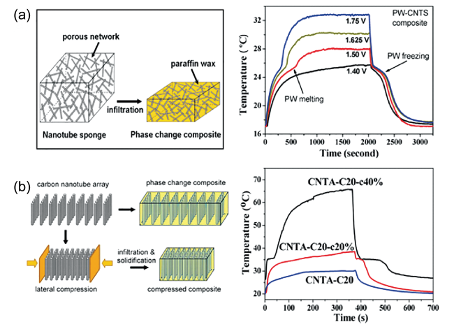
图4 (a)随机分布碳纳米管泡沫复合相变材料与电热转换[41];(b)定向排列碳纳米管阵列复合相变材料与电热转换[43]

Fig. 4 (a) randomly distributed CNT sponge PCCs and its electrothermal conversion[41]. Copyright © 2012, American Chemical Society; (b) aligned CNT array PCCs and its electrothermal conversion[43]. Copyright © 2013, American Chemical Society

In order to further improve the electrothermal conversion efficiency, Zou et al. prepared anisotropic vertically aligned carbon nanotube arrays (CNTA) by CVD method, and adjusted the density of carbon nanotubes by compression, as shown in Fig. 4B[43]. Through melt impregnation, eicosane (C20) was adsorbed into CNTA as a phase change material, thus filling the gaps between the parallel carbon nanotubes and maintaining the alignment and interconnection of the carbon nanotubes between the matrices. With the volume compression, the minimum required applied voltage also decreases. When the volume compression ratio is 40%, the minimum required applied voltage for electrothermal conversion is only 1 V. When the applied voltage is 1. 3 V, the electrothermal conversion efficiency is 74. 7%, which is higher than that of random distribution.
On this basis, in view of the problem that the volume change during phase change often leads to leakage, Zou et al. Prepared PU @ CNTS with anisotropy, flexibility, bimorphous stability and photothermal-electrothermal conversion ability by combining carbon nanotube foam and polyurethane solid-solid phase change materials[42]. It is worth mentioning that the CNTS in CNTS are oriented along the horizontal direction due to the repulsion caused by the opposite polarity of hydrophilic PU and hydrophobic CNTs, which provides good energy conversion performance for PU @ CNTs. When the applied voltage is 2 V, the electrothermal conversion efficiency reaches 94%, showing the excellent performance of high electrothermal conversion efficiency at low voltage. At the same time, the latent heat of PU @ CNTS is 132 J/G, which is close to the latent heat of PU solid-solid phase change material 150.16 J/G.
Carbon foam (CF) has high specific surface area, large pore volume, good mechanical stability and high electrical/thermal conductivity, and compared with graphite foam, the preparation temperature is low, the preparation is relatively simple, and the CF can well encapsulate the phase change material and enhance the thermal/electrical conductivity of the composite material[66]. Maleki et al. Obtained three-dimensional interconnected porous carbon foams with high specific surface area (540 m2/g) by pyrolysis at 900 ° C under nitrogen using polymerized high internal phase emulsion as a substrate[36]. CFs/PA and CFs/PEG shape-stabilized phase change materials with latent heat of 120.02 J/G and 163.9 J/G, respectively, were subsequently prepared by melt impregnation. After testing, the conductivity of carbon foam is 341 S/m, which is much higher than that of graphene aerogel prepared by supercritical ethanol drying and high temperature thermal reduction (53.5 – 157.3 S/m), and the electrothermal conversion efficiency of CFs/PA and CFs/PEG is 73% and 85%, respectively, when the applied voltage is 3.6 V.
In the process of practical application, it is very important to reduce the cost of materials. Umair et al. Synthesized a carbon scaffold (HCF) with excellent porosity from raw cotton and prepared a HCF-PW composite phase change material by vacuum melting and adsorbing paraffin. The existence of a long carbon fiber conductive three-dimensional network in the composite endows the composite with efficient electrothermal conversion capability[38]. The latent heat of HCF-PW is 182. 22 J/G, and the conductivity is 19. 6 S/m. The phase transition can occur when the applied voltage is greater than 2 V, and the electrothermal conversion efficiency is 81. 1% when the applied voltage is 3 V. Aiming at the problem of leakage caused by the fragile folding of PCM blocks, Chen et al. Prepared single-walled carbon nanotube framework (SWCNT)/eicosane flexible PCM film with CaCl2 as dispersant[44]. With the increase of SWCNT content (22. 9 wt% ~ 33.4 wt%), the conductivity of the materials gradually increases (531. 2 ~ 3927. 3 S/m), but the electrothermal conversion efficiency decreases (91. 3% ~ 51.1%) with the increase of SWCNT content due to the influence of energy capacity, resistance and environmental heat flow loss. The electrothermal conversion temperature decreases when the SWCNT content is too low, and the energy storage capacity decreases when the SWCNTs content is too high, which will lead to the electrothermal conversion efficiency. When the proportion of SWCNT is 27.1 wt%, the electrothermal conversion efficiency is 91.3% at 5 V.

3.2.2 Graphite based conductive skeleton

Graphite-based conductive frameworks mainly include graphite foams and graphite nanosheets. Graphite foam (GF) can be obtained by further graphitization of carbon foam at a temperature of 2500 ~ 3000 ℃, and its highly ordered porous carbon structure can effectively improve the electrothermal conversion ability of the composite, while the lower cost compared with CNT and GO is more conducive to practical applications[67].
Zou et al. Obtained shape-stable PU/GF composite phase change materials by direct curing of PEG in GF, and showed high electrothermal conversion ability, but the curing of PU also led to a decrease in latent heat of phase change[46]. When the phase change material is PEG6000, the latent heat of PU/GF is 76. 1 J/G and the electrothermal conversion efficiency is 82% ~ 85% at low voltage (1. 2 ~ 1.4 V). On this basis, Wu et al. Prepared PU/GF composite phase change materials with commercial sponge adsorbing asphalt as raw material and showed close electrothermal conversion ability[47]. The latent heat of PU/GF is 60. 3 J/G, and the electrothermal conversion efficiency is 85% at an applied voltage of 1. 8 V. In order to solve the recycling problem of waste lithium-ion batteries, Liu et al. Prepared graphite foam with pore size of 5. 4-351. 9 μm by treating graphite powder extracted from the cathode of lithium-ion batteries at 900 ℃, and its hydrophobicity promoted the penetration of PW. The latent heat of phase change of PW/GF was 174. 2 J/G, and the electrothermal conversion efficiency was 74. 6% at 5 V voltage[45].
Reticulated graphite nanosheets (RGNPs) have an aligned layered structure, which is beneficial to the electron transfer and phonon transport in the material, reduces the interfacial thermal resistance and enhances the thermal conduction, and effectively improves the electrothermal conversion and storage capacity of the composite[68]. Using pentaerythritol (PE) as a solid-solid phase change material and self-assembled graphite nanosheets as a conductive framework, Li et al. Prepared a composite phase change material with high thermal conductivity and extremely high electrical conductivity in the same direction as the thermal energy transfer direction by pressure orientation, using a customized strategy in which the direction of high thermal conductivity is parallel to the direction of electrical transport, which is 33.5 W/mK and 32 300 S/m, respectively.At the same time, due to the high phase transition temperature (186 ℃) and high phase transition latent heat (281. 5 J/G) of PE, the phase transition latent heat of the composite is 225. 3 J/G, and the high heat storage capacity and the construction of the directional electrical and thermal conduction network make the composite show excellent electrothermal conversion capacity.When the applied voltage is only 0. 34 V, the electrothermal conversion efficiency of the material reaches 92. 73%, which is also the lowest working voltage and the highest electrothermal conversion efficiency of the electrothermal phase change material in the current research[50]. Furthermore, aiming at the problem of material leakage after phase change, Li et al. Used a simple pressure-induced assembly method to manufacture double-packaged PU-RGNPs composite phase change materials. Because of the internal directional layered structure,The material exhibits anisotropic high thermal conductivity (27.0 W/mK) and high electrical conductivity (51 S/m in the radial direction and 10 S/m in the axial direction), so it has extremely high electrothermal conversion efficiency at low voltage, up to 92.1% when the applied voltage is 1.2 V[49].

3.2.3 Graphene-based conductive skeleton

The graphene-based conductive skeleton is mainly composed of graphene and its mixture aerogel, and its small pore size provides better shape stability for the composite and has a high phase change enthalpy at low load, which is one of the most promising phase change composites at present[69]. Aiming at the isotropic disordered porous structure in aerogel and the limitation of long transmission path on fast transmission, Li et al. Synthesized graphene aerogel/paraffin (PW/GA) composite phase change materials with oriented structure anisotropy by using the oriented arrangement of graphene oxide liquid crystal in water dispersant[54]. The thermal and electrical conductivities are significantly different in the axial and radial directions. The axial electrical/thermal conductivities are 341.3 S/m and 1.71 W/mk, respectively, which are 4 ~ 5 times and 8 times higher than the radial electrical/thermal conductivities, respectively. Therefore, the PW/GA exhibits a high electrothermal conversion efficiency (85.4%) at a lower voltage (3 V) due to the directional and rapid transmission of electric heat.
Graphene nanoplates (GNP) are difficult to disperse in solvents due to their chemical inertness and extremely weak interactions, and Wei et al. Synthesized MCC/GNP aerogel materials using microcrystalline cellulose (MCC) as a dispersant[58]. MCC promotes the synthesis of aerogel and the oriented packing of GNP, resulting in the fabrication of anisotropic conductive frameworks. The MCC/GNP/PEG phase change material adsorbed by vacuum melting has a higher latent heat (185.6 J/G) than that of pure PEG (182.9 J/G) due to the promotion of crystallization of PEG by MCC, and has the ability of electrothermal conversion. Wu et al. Used a similar method to prepare a nanocellulose/graphite nanoplate/melamine foam/polyethylene glycol (CG @ MF/PEG) composite with a latent heat of 182.4 J/G and a conductivity of 6.19 S/m.The electrothermal conversion efficiency is 66. 13% at a voltage of 20 V. The required external voltage is large, and the electrothermal conversion efficiency is low, which is due to the low electrical conductivity and thermal conductivity of cellulose itself, which limits the electrothermal conversion and transmission[59]. Umair et al. Extracted and carbonized graphene oxide (GO) -doped cellulose acetate fiber scaffolds from waste cigarette filters, and the carbonized conductive scaffolds adsorbed PW to form composite phase change materials, which showed higher conductivity (294.9 S/m) and electrothermal conversion efficiency (88%) than MCC/GNP/PEG and CG @ MF/PEG[51].

3.2.4 Other Conductive Skeleton

Similar to the previous paper, other conductive frameworks mainly include metal foams and new conductive materials such as MOF and MXene. Zhang et al. Prepared copper nanowire aerogel/paraffin (CuNWA-P) composite phase change materials by supercritical drying and vacuum adsorption of paraffin, and studied the effect of sintering on the interfacial bonding and the electrical/thermal conductivity of the materials[62]. The results show that the residual functional groups can be removed by sintering, thus reducing the contact resistance between CuNWAs, and the conductivity of the material increases from 3. 03 S/m to 9. 6 S/m by sintering at 200 ℃. Jin et al. Synthesized a PEDOT: PSS/MXene conductive framework with an oriented structure by an ice template method. Due to the effect on the crystallization of PEG, the composite showed a higher latent heat of phase transition (237.6 J/G) than pure PEG (225.1 J/G)[64]. The alignment of PEDOT: PSS/MXene enhances the conductivity of the material, increasing the conductivity to 0.86 S/m and exhibiting the electrothermal conversion ability at 30 V.
Metal-organic framework carbide (MOF-C) with mesoporous structure and ultra-high pore volume has shown great potential in the preparation of highly shape-stable phase change composites with large loading capacity of phase change materials[70~72]. Wang et al. Synthesized MOF-C/GO mixed aerogel by filling the macropores in GO with MOF-C particles, and the synergistic effect of the two further enhanced the loading capacity of the phase change material. The latent heat of phase change of LA/MOF-C/GO was 140 J/G, which was much higher than that of LA/GO (60 J/G) and LA/MOF-C (120 J/G)[60]. At the same time, the network structure of the hybrid aerogel is denser than that of the MOF-C particle aggregate and GO aerogel, which improves the electrothermal conversion ability, and the electrothermal conversion efficiency is 90% when the applied voltage is 2. 2 V.

3.3 Intrinsic Conductive Polymer Composite Electrothermal Phase Change Material

Intrinsic conducting polymers contain conjugated long chain structure, and the delocalized π electrons on the double bond can migrate on the molecular chain to form current, which makes the polymer structure inherently conductive and has potential value in the study of electrothermal conversion phase change materials. At present, there are few studies on this kind of composite materials, mainly on polypyrrole composite phase change materials. Polypyrrole (PPy) is a conductive polymer polymerized by pyrrole rings, which has high conductivity and better flexibility than most conductive polymers, so it is widely used in supercapacitors, personal temperature management and other fields[78~80]. Due to its low adsorption capacity, it is difficult to adsorb phase change materials to form a shape-stable structure. At present, polypyrrole is mainly combined with supporting materials by rapid oxidation-induced polymerization to prepare shape-stable composite phase change materials.Its conductivity is generally high, but the low thermal conductivity of the polymer limits the heat transfer capacity of the material, and its electrothermal conversion efficiency is higher than that of the conductive filler, and slightly lower than that of the conductive skeleton material with a directional structure, as shown in Table 3.
表3 导电高分子复合电热相变材料性能

Table 3 Properties of conductive polymer electrothermal phase change composites

Conductive polymer PCMS Filler content
(wt%)
Tm
( ℃)
Latent heat
(J/g)
λW/
(m·K)
σ
(S/m)
The trigger voltage(V) η
(%)
The working voltage(V) ref
PPy/crosslinked polystyrene paraffin wax - 44.9 114.2 - 420 1.8 63.2 1.8 73
PPy/crosslinked polystyrene paraffin wax - 44.9 114.2 - 420 1.8 80.1 3 73
PPy/ polydivinylbenzene nanotubes paraffin wax 27.1 30 145.7 - 55.6 - 66.8 2.2 74
PPy/ polydivinylbenzene nanotubes paraffin wax 27.1 30 145.7 - 55.6 - 89.6 2.5 74
PPy/Cellulose
nanofiber
PEG 6 57.41 169.7 - - 1.75 76.6 1.75 75
PPy/Cellulose
nanofiber
PEG 6 57.41 169.7 - - 1.75 85.1 1.9 75
PPy/melamine-
formaldehyde
n-octadecane 50.3 30 90.2 - 0.33 - - - 76
PPy/PU PEG 60.8 47.5 62.8 - 1184 - - - 77
Cheng et al. Prepared IPW @ CLPS @ PPy nanocapsule phase change materials by rapid oxidative chemical polymerization with industrial paraffin (IPW) as the core, crosslinked polystyrene (CLPS) as the supporting inner layer, and polypyrrole (PPy) as the bifunctional outer layer[73]. The double shell structure makes the material have excellent thermal stability, and also reduces the latent heat of phase change (114. 2 J/G). Compared with the conductivity of IPW(10-14S/m) and IPW @ CLPS (5. 8 S/m), the construction of PPy conductive layer significantly improves the conductivity of the material, and the conductivity increases to 420 S/m, and the electrothermal conversion efficiency is 63. 2% ~ 80.1% when the applied voltage is 1. 8 ~ 3.0 V. Kong et al. Constructed PDVB-12/PPy NTs by wrapping PPy on mesoporous poly (divinylbenzene) nanotubes (PDVB-12 NTs) through rapid oxidation method, and then prepared IPW @ PDVB- 12/PPy phase change materials through vacuum melting adsorption[74]. Benefiting from the electrothermal transmission pathway provided by PPy, the conductivity of the material is 55.6 S/m, and the electrothermal conversion efficiency is 66.8% ~ 89.6% when the applied voltage is 2.2 ~ 2.5 V.

4 Application of Electrothermal Phase Change Materials

Compared with the low thermal conductivity (≤ 0.4 W/ (m · K)) and low electrical conductivity (<10-6S/m) of most pure PCMs, electrothermal PCMs have higher thermal conductivity and electrical conductivity, which means that they not only have the ability of passive heat storage and temperature control of PCMs, but also can realize active electricity-heat conversion, thermal energy storage and temperature management by applying voltage. Different application scenarios have different requirements for the thermal conductivity, latent heat and phase change temperature of phase change materials, so the potential applications of conductive phase change materials reported so far can be roughly divided accordingly. As shown in fig. 5A, high-power and high-temperature electrothermal conversion and storage has higher requirements for thermal conductivity, phase change latent heat and electrical conductivity; Temperature control systems that require rapid heating and heat dissipation, such as battery heat preservation and heat dissipation, require higher thermal conductivity. Electrothermal conversion and storage at room temperature, housing, human body heat preservation and heat dissipation and other scenarios are in pursuit of low thermal conductivity and high demand for phase change enthalpy. In addition, the response sensitivity brought by high conductivity and the large energy density brought by latent heat value make the electrothermal phase change materials have potential application value in the fields of low and high temperature thermal protection, fine temperature control of feedback electrothermal system, and rapid heat transfer.
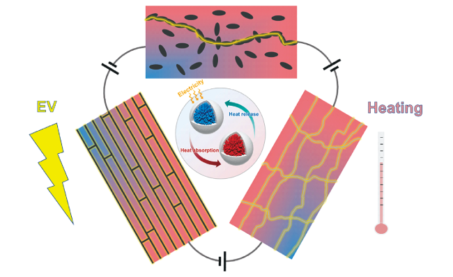
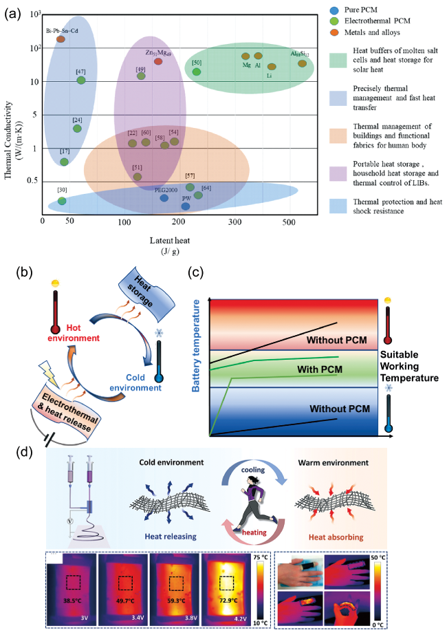
图5 (a)电热相变材料的应用;(b)电热相变材料应用示意图;电热相变材料用于(c)电池温度管理和(d)人体保温[28]

Fig. 5 (a) Application of electrothermal PCCs, (b) Application mode of electrothermal PCCs, (c) Temperature change of battery with or without electrothermal PCCs, (d) PCCs for human thermal insulation[28]. Copyright ©#x00A9; 2022, American Chemical Society

In terms of thermal energy storage, Li et al. Prepared electrothermal phase change materials with PE as phase change materials by pressure-induced method, with thermoelectric conductivities of 33. 5 W/ (m · K) and 32 300 S/m, phase change temperature of 186 ℃, and latent heat of 225. 3 J/G[50]. Due to the significant advantages of ultra-high thermal conductivity, ultra-low driving voltage and large thermal capacity, the excellent thermal performance and synergistic effect enable the PCC-based multi-functional energy device to be used for indirect solar photovoltaic conversion and collection, as well as the storage and reuse of off-peak power from the grid or surplus power from other renewable energy sources.
In terms of temperature management, electrothermal phase change materials have both passive heat storage and active electric heating capabilities, so they can delay temperature rise through phase change heat storage in high temperature environment.In low temperature environment, the temperature can be increased by active heating and passive heat release, as shown in Figure 5B. It has application value in the fields of house temperature control, battery thermal management and human body heat preservation.
Frac et al. Prepared cement phase change materials by mixing expanded graphite and paraffin in cement and tested their effects on the temperature change of houses[22]. As the voltage switch is turned on, the material surface temperature rises to 70 ℃ at about 1200 s, and the ambient temperature rises from 20 ℃ to 30 ℃. After the switch is turned off, the ambient temperature of the phase change concrete is higher than that of the concrete without phase change material at 20 minutes, which shows the ability of keeping warm and controlling the temperature of the house when the ambient temperature rises or falls. According to the simulation calculation, when the volume of the concrete material used is 1.2 m3 and the outside temperature is -20 ℃, the material after heat storage can maintain the indoor temperature of 22 ℃ for 4.7 H.
Electrothermal phase change materials have excellent battery temperature management capability, which can effectively keep the temperature of the battery pack around the optimal working temperature, thereby improving the working efficiency and safety of the battery pack. The principle is shown in Figure 5C. Zhang et al. Synthesized EG/PW electrothermal phase change materials and studied their battery temperature management capabilities[23]. The PCC can heat the battery module from -25 ℃ to 35 ℃ at a heating rate of 13.4 ℃/min under an applied voltage of 3.4 V, and the internal temperature difference is only 3.3 ℃. Furthermore, the thermal management model of the battery is constructed through numerical simulation, and the thermal management performance of the 56-cell battery pack is successfully designed and tested. The results show that when the ambient temperature is from-40 ℃ to 50 ℃, the battery thermal management system successfully maintains the temperature in the range of 25 ℃ to 55 ℃ through the electrothermal phase change material, and the temperature difference of the battery is less than 3. 9 ℃, which shows that the system has the ability to be extended to practical use. Wu et al. Studied the temperature management ability of the synthesized polyurethane/graphite nanoplates for the battery[49]. When the battery is in a low temperature environment, the lithium ion battery is preheated by the Joule heat stored by the electrothermal conversion of the phase change material in the starting stage, when the external environment is 0 ℃, the temperature of the battery rises rapidly to 40 ℃ and remains at 34 ~ 40 ℃ for a long time, and the temperature of the battery pack without the phase change material is 0 ~ 11 ℃ for a long time. In the high temperature environment, the heat released by the lithium battery is absorbed, stored and rapidly dissipated through phase change. When the external environment is 35 ℃, the maximum temperature of the bare lithium battery in discharge is 70 ℃, while the maximum temperature of the wrapped lithium battery pack is 55 ℃. The battery can maintain the best working temperature in both low and high temperature environments, thus avoiding the risk of capacity loss, life shortening and even thermal runaway of lithium batteries.
According to the different ambient temperature, the electrothermal phase change material can regulate the human body temperature by passively absorbing heat, heating by a miniature battery, charging in advance to store heat and releasing heat at a low temperature, so as to achieve the purpose of heat preservation. Wu et al. used coaxial electrospinning to construct a wearable temperature-regulated textile with paraffin as the core and PU, CNT, PDA and PEDOT: PSS as the multi-shell structure, and showed the ability to rapidly heat up at low voltage (3.0 ~ 4.2 V), as shown in Figure 5d. The film has good flexibility and is directly wrapped on the human finger to produce heating effect by electric drive[28]. At the same time, due to the existence of heat loss, the temperature of the material will not rise indefinitely, but will maintain thermal balance at different temperatures according to different applied voltages, so the constant temperature of the material can be adjusted according to different heat preservation requirements, so that the human body is always at a suitable temperature.
In practical applications, the electrothermal conversion phase change heat storage material can be directly loaded in the existing production industrial circuit system due to the improvement of conductivity by using conductive fillers, skeletons or groups, and can be applied to systems such as electrothermal storage and temperature control by using the Joule heat principle. Therefore, in a simplified Joule heating circuit, the conductive phase change material is simplified as a common ohmic heating resistor, and the existing circuit system is simplified as a power supply system with an internal resistor, so that the electric heating power P generated on the conductive phase change material and the corresponding electric energy utilization efficiency eff can be roughly calculated according to the following formula:
P = ( E R + r ) 2 R e f f = R R + r
Where P: power (W), E: voltage (V), eff: energy utilization efficiency (%), R: material resistance (Ω), R: circuit internal resistance (Ω)
For a certain power supply system, when the equivalent internal resistance R of the circuit is fixed, the influence of the change of the resistance value R of the electrothermal phase change energy storage module on the electrothermal heat storage power and the system energy efficiency is shown in Figure 6. When the resistance is far less than the internal resistance, the electric energy efficiency is very low, which is mainly consumed on non-heating components such as wires and transformers. When the resistance is much greater than the internal resistance, the electric energy utilization rate of the phase change heat storage component is very high, but the overall heating power of the circuit is too low, and the generated heat can not activate the material to reach the phase change temperature in the case of heat loss. Therefore, according to the resistance and voltage of the power supply system, it is very important to select the composite phase change material with appropriate conductivity to maintain its working range.
图6 电热相变材料的选择

Fig. 6 Selection of electrothermal phase change materials

5 Conclusion and prospect

Electrothermal conversion functional phase change materials can effectively convert electric energy into heat energy for storage and reuse, which has important application value in power peak shaving, heat energy storage, temperature management and other fields. In this paper, the composite phase change materials with conductive filler, loaded conductive skeleton or conductive polymer polymerization were reviewed and compared. The electrothermal conversion efficiency is affected by the type of composite, pore structure, orientation and spatial arrangement, synergistic effect, thermal properties and so on.Composite phase change materials loaded with conductive skeletons with highly oriented structure and electrothermal coupling often show higher electrothermal conversion efficiency at low voltage, and at the same time, they can well realize the packaging of phase change materials and maintain high latent heat of phase change, which has unique advantages.
For the electrothermal conversion phase change materials, there are still some key issues worthy of study: (1) At present, the supporting materials are mainly carbon-based materials, and the electrothermal conversion ability and its influencing factors of new conductive phase change materials and conductive polymer composites with higher conductivity, such as MXene and liquid metal (LM), need to be further studied; (2) Low-temperature phase change alloys and metals can realize electrothermal conversion and storage without adding conductive materials, and have potential research value because of their small supercooling degree and sensitive temperature response, but their high conductivity and relatively high phase change temperature make it a challenge to realize electrothermal conversion and latent heat storage at low voltage; (3) The electrothermal phase change material with orientation structure and conductive heat transfer path coupling can effectively improve its conductivity, thermal conductivity and electrothermal conversion efficiency and show anisotropy, so the electrothermal performance of the material can be effectively regulated by designing different orientations and conductive heat transfer paths.This is of great significance to further improve the electrothermal conversion efficiency and regulate the material properties according to the actual application, while the enhancement mechanism, micro-mechanism and how to reduce the heat flow loss still need further study. (4) At present, the research on electrothermal phase change materials mainly focuses on improving its conductivity and ensuring a higher latent heat value. There are many studies on the lower limit of the driving voltage, but there is almost no study on the upper limit of the driving voltage. The composition of the components in the electrothermal phase change materials.There is an upper limit of heat transfer efficiency between the conductive path and the non-conductive part caused by the contact interface, which leads to the upper limit of driving voltage and electrothermal power of the material. It is expected that there is a coordination between the latent heat value and the upper limit of power, which is of great significance for the application adaptability of electrothermal phase change materials. (5) Although it has been made clear that electrothermal conversion materials have application value in temperature management, electrothermal conversion storage and other fields, and some equipment has been realized in aerospace, national defense and military industry.However, there are still limitations such as cost and energy storage power before the actual large-scale realization, and how to design the corresponding structure and material electric conductivity performance according to the application scenarios still needs further study.
In a word, in today's frequent energy, environmental and climate crises, especially considering the role of energy in the international situation and the background of China's double carbon target.Electrothermal conversion, storage and reuse are of great significance. The research on electrothermal materials is still in its infancy and in the ascendant. The follow-up research on such materials is expected to achieve further breakthroughs and applications in the field of energy.
[1]
Sundararajan S, Samui A B, Kulkarni P S. J. Mater. Chem. A, 2017, 5(35): 18379.

[2]
Zhang Y A, Umair M M, Zhang S F, Tang B T. J. Mater. Chem. A, 2019, 7(39): 22218.

[3]
Henry A, Prasher R, Majumdar A. Nat. Energy, 2020, 5(9): 635.

[4]
Su W G, Darkwa J, Kokogiannakis G. Renew. Sustain. Energy Rev., 2015, 48: 373.

[5]
Aftab W, Usman A, Shi J M, Yuan K J, Qin M L, Zou R Q. Energy Environ. Sci., 2021, 14(8): 4268.

[6]
Aydin D, Casey S P, Riffat S. Renew. Sustain. Energy Rev., 2015, 41: 356.

[7]
Hyun D C, Levinson N S, Jeong U, Xia Y N. Angew. Chem. Int. Ed., 2014, 53(15): 3780.

[8]
Liu W, Zhang X L, Ji J, Wu Y F, Liu L. Energy Technol., 2021, 9(7): 2100169.

[9]
Tahan Latibari S, Sadrameli S M. Sol. Energy, 2018, 170: 1130.

[10]
Kalidasan B, Pandey A K, Shahabuddin S, Samykano M, Thirugnanasambandam M, Saidur R. J. Energy Storage, 2020, 27: 101118.

[11]
Wang W T, Tang B T, Ju B Z, Gao Z M, Xiu J H, Zhang S F. J. Mater. Chem. A, 2017, 5(3): 958.

[12]
Wang W T, Fan X Q, Qiu J J, Umair M M, Ju B Z, Zhang S F, Tang B T. Chem. Eng. J., 2018, 358.

[13]
Fan X Q, Xiao J Q, Wang W T, Zhang Y A, Zhang S F, Tang B T. Polymers, 2018, 10(6): 585.

[14]
Horsfield A P, Bowler D R, Fisher A J, Todorov T N, Montgomery M J. J. Phys.: Condens. Matter, 2004, 16(21): 3609.

[15]
Zhang H Q, Sun Q R, Yuan Y P, Zhang Z J, Cao X L. Chem. Eng. J., 2018, 336: 342.

[16]
Zhang K, Han B G, Yu X. Energy Convers. Manag., 2012, 64: 62.

[17]
Cao R R, Chen S, Wang Y Z, Han N, Liu H H, Zhang X X. Carbon, 2019, 149: 263.

[18]
Sun Q R, Zhang N, Zhang H Q, Yu X P, Ding Y L, Yuan Y P. Renew. Energy, 2020, 145: 2629.

[19]
Sun Q R, Zhang N, Yu X P, Ju F L, Szilágyi I M, Yuan Y P. Int. J. Energy Res., 2021, 45(5): 7675.

[20]
Tabassum H, Huang X Y, Chen R J, Zou R Q. J. Materiomics, 2015, 1(3): 229.

[21]
Li C C, Zhang B, Liu Q X. J. Energy Storage, 2020, 29: 101339.

[22]
Frᶏc M, PichÓr W, Szołdra P, Szudek W. Constr. Build. Mater., 2021, 275: 122126.

[23]
Luo M Y, Song J Q, Ling Z Y, Zhang Z G, Fang X M. Mater. Today Energy, 2021, 20: 100652.

[24]
Cao R R, Wang Y Z, Chen S, Han N, Liu H H, Zhang X X. ACS Appl. Mater. Interfaces, 2019, 11(9): 8982.

[25]
Guo X F, Liu C, Li N, Zhang S D, Wang Z Y. Ind. Eng. Chem. Res., 2018, 57(46): 15697.

[26]
Zheng Z L, Jin J D, Xu G K, Zou J L, Wais U, Beckett A, Heil T, Higgins S, Guan L H, Wang Y, Shchukin D. ACS Nano, 2016, 10(4): 4695.

[27]
Yu C B, Youn J R, Song Y S. Fibers Polym., 2019, 20(3): 545.

[28]
Wu J J, Wang M X, Dong L, Shi J, Ohyama M, Kohsaka Y, Zhu C H, Morikawa H. ACS Nano, 2022, 16(8): 12801.

[29]
Niu Z X, Qi S Y, Shuaib S S A, Yuan W Z. Compos. B Eng., 2022, 228: 109431.

[30]
Yu L X, Qin X H, Ke G Z, Tang J N, Wang Y. Compos. Commun., 2022, 32: 101152.

[31]
Lu X, Huang H W, Zhang X Y, Lin P C, Huang J T, Sheng X X, Zhang L, Qu J P. Compos. B Eng., 2019, 177: 107372.

[32]
Janas D, Koziol K K. Nanoscale, 2014, 6(6): 3037.

[33]
Wu Y P, Wang T. Energy Convers. Manag., 2015, 101: 164.

[34]
Nat. Nanotechnol. 2010, 5: 755.

[35]
Wang J F, Shen M M, Liu Z X, Wang W J. Nano Energy, 2022, 97: 107177.

[36]
Maleki M, Karimian H, Shokouhimehr M, Ahmadi R, Valanezhad A, Beitollahi A. Chem. Eng. J., 2019, 362: 469.

[37]
Wu W H, Huang X Y, Yao R M, Chen R J, Li K, Zou R Q. Acta Phys. Chim. Sin. 2017, 33(1): 255.

[38]
Umair M M, Zhang Y A, Tehrim A, Zhang S F, Tang B T. Ind. Eng. Chem. Res., 2020, 59(4): 1393.

[39]
Li Y Q, Samad Y A, Polychronopoulou K, Alhassan S M, Liao K. J. Mater. Chem. A, 2014, 2(21): 7759.

[40]
Umair M M, Zhang Y A, Zhang S F, Jin X, Tang B T. J. Mater. Chem. A, 2019, 7(46): 26385.

[41]
Chen L J, Zou R Q, Xia W, Liu Z P, Shang Y Y, Zhu J L, Wang Y X, Lin J H, Xia D G, Cao A Y. ACS Nano, 2012, 6(12): 10884.

[42]
Aftab W, Mahmood A, Guo W H, Yousaf M, Tabassum H, Huang X Y, Liang Z B, Cao A Y, Zou R Q. Energy Storage Mater., 2019, 20: 401.

[43]
Liu Z P, Zou R Q, Lin Z Q, Gui X C, Chen R J, Lin J H, Shang Y Y, Cao A Y. Nano Lett., 2013, 13(9): 4028.

[44]
Chen R J, Huang X Y, Deng W B, Zheng R Z, Aftab W, Shi J M, Xie D L, Zou R Q, Mei Y. Appl. Energy, 2020, 260: 114320.

[45]
Liu M Y, Zhang X G, Liu X J, Wu X W, Ye X J, Qiao J X, Sun Z H, Zhu X, Huang Z H. ACS Sustainable Chem. Eng., 2022, 10(24): 8051.

[46]
Chen R J, Yao R M, Xia W, Zou R Q. Appl. Energy, 2015, 152: 183.

[47]
Wu W H, Huang X Y, Li K, Yao R M, Chen R J, Zou R Q. Appl. Energy, 2017, 190: 474.

[48]
Wu W H, Yao R M, Huang X Y, Chen R J, Li K, Gao S, Zou R Q. Mater. Chem. Front., 2017, 1(7): 1430.

[49]
Wu M Q, Li T X, Wang P F, Wu S, Wang R Z, Lin J. Small, 2022, 18(9): 2105647.

[50]
Li T X, Wu M Q, Wu S, Xiang S Z, Xu J X, Chao J W, Yan T S, Deng T, Wang R Z. Nano Energy, 2021, 89: 106338.

[51]
Umair M M, Zhang Y A, Zhang S F, Jin X, Tang B T. Sustain. Energy Fuels, 2020, 4(8): 4285.

[52]
Yang G Q, Zhao L Y, Shen C F, Mao Z P, Xu H, Feng X L, Wang B J, Sui X F. Sol. Energy Mater. Sol. Cells, 2020, 209: 110441.

[53]
Ye S B, Zhang Q L, Hu D D, Feng J C. J. Mater. Chem. A, 2015, 3(7): 4018.

[54]
Li G Y, Zhang X T, Wang J, Fang J H. J. Mater. Chem. A, 2016, 4(43): 17042.

[55]
Zhou Y, Wang X J, Liu X D, Sheng D K, Ji F C, Dong L, Xu S B, Wu H H, Yang Y M. Sol. Energy Mater. Sol. Cells, 2019, 193: 13.

[56]
Zhou Y, Wang X J, Liu X D, Sheng D K, Ji F C, Dong L, Xu S B, Wu H H, Yang Y M. Carbon, 2019, 142: 558.

[57]
Cai Y X, Zhang N, Yuan Y P, Zhong W, Yu N Y. Sol. Energy Mater. Sol. Cells, 2021, 233: 111390.

[58]
Wei X, Xue F, Qi X D, Yang J H, Zhou Z W, Yuan Y P, Wang Y. Appl. Energy, 2019, 236: 70.

[59]
Wu H Y, Deng S, Shao Y W, Yang J H, Qi X D, Wang Y. ACS Appl. Mater. Interfaces, 2019, 11(50): 46851.

[60]
Wang M, Zhang C, Wang J Z, Wang Y, Yu F Q. J. Energy Storage, 2022, 52: 104905.

[61]
Li A, Dong C, Dong W J, Yuan F G, Gao H Y, Chen X, Chen X B, Wang G. Adv. Electron. Mater., 2020, 6(6): 1901428.

[62]
Zhang L, An L, Wang Y H, Lee A, Schuman Y, Ural A, Fleischer A S, Feng G. Chem. Eng. J., 2019, 373: 857.

[63]
Cao X Y, Yang L J, Cui J, Feng Q B, Wang C J, Zhu Z Q, Sun H X, Li J Y, Liang W D, Li A. Colloids Surf. A Physicochem. Eng. Aspects, 2022, 651: 129516.

[64]
Jin X Z, Yang Z Y, Huang C H, Yang J H, Wang Y. Chem. Eng. J., 2022, 448: 137599.

[65]
Paul J, Pandey A K, Mishra Y N, Said Z, Mishra Y K, Ma Z J, Jacob J, Kadirgama K, Samykano M, Tyagi V V. Renew. Sustain. Energy Rev., 2022, 161: 112321.

[66]
Inagaki M, Qiu J S, Guo Q G. Carbon, 2015, 87: 128.

[67]
Kim J H, Jeong E, Lee Y S. J. Ind. Eng. Chem. 2015, 32: 21.

[68]
Wu S, Li T X, Tong Z, Chao J W, Zhai T Y, Xu J X, Yan T S, Wu M Q, Xu Z Y, Bao H, Deng T, Wang R Z. Adv. Mater., 2019, 31(49): 1905099.

[69]
Kashyap S, Kabra S, Kandasubramanian B. J. Mater. Sci., 2020, 55(10): 4127.

[70]
Aftab W, Huang X Y, Wu W H, Liang Z B, Mahmood A, Zou R Q. Energy Environ. Sci., 2018, 11(6): 1392.

[71]
Chen X, Gao H Y, Yang M, Xing L W, Dong W J, Li A, Zheng H Y, Wang G. Energy Storage Mater., 2019, 18: 349.

[72]
Chen X, Gao H Y, Tang Z D, Wang G. Cell Rep. Phys. Sci., 2020, 1(10): 100218.

[73]
Cheng L Q, Kong L B, Zhang X, Kong X F. Sol. Energy Mater. Sol. Cells, 2022, 235: 111461.

[74]
Kong L B, Wang Z Y, Kong X F, Wang L, Ji Z Y, Wang X M, Zhang X. ACS Appl. Mater. Interfaces, 2021, 13(25): 29965.

[75]
Chen L Y, Lv J C, Ding L, Yang G Q, Mao Z P, Wang B J, Feng X L, Zapotoczny S, Sui X F. Chem. Eng. J., 2020, 400: 125950.

[76]
Yun H R, Li C L, Zhang X X. e-Polymers, 2019, 19(1): 519.

[77]
Gao M H, Feng W, Qi X D, Wang Y. Chin. J. Polym. Sci., 2022, 40(11): 1380.

[78]
Huang Y, Li H F, Wang Z F, Zhu M S, Pei Z X, Xue Q, Huang Y, Zhi C Y. Nano Energy, 2016, 22: 422.

[79]
Yan Q S, Du X X, Liu Y, Zhou X, Xin B J. ACS Appl. Mater. Interfaces, 2022, 14(21): 24820.

[80]
Lv J C, Zhou P W, Zhang L P, Zhong Y, Sui X F, Wang B J, Chen Z Z, Xu H, Mao Z P. Chem. Eng. J., 2019, 361: 897.

Outlines

/