Home Journals Progress in Chemistry
Progress in Chemistry

Abbreviation (ISO4): Prog Chem      Editor in chief: Jincai ZHAO

About  /  Aim & scope  /  Editorial board  /  Indexed  /  Contact  / 
Review

Development of Na-Based Seawater Batteries: “Key Components and Challenges”

  • Niu Wenhui 1, 2, 3 ,
  • Zhang Da , 1, 2, 3, * ,
  • Zhao Zhengang 1, 2, 3 ,
  • Yang Bin 1, 2, 3 ,
  • Liang Feng , 1, 2, 3, *
Expand
  • 1. Key Laboratory for Nonferrous Vacuum Metallurgy of Yunnan Province, Kunming University of Science and Technology,Kunming 650093, China
  • 2. National Engineering Research Center of Vacuum Metallurgy, Kunming University of Science and Technology,Kunming 650093, China
  • 3. Faculty of Metallurgical and Energy Engineering, Kunming University of Science and Technology,Kunming 650093, China
* Corresponding author e-mail: (Feng Liang);
(Da Zhang)

Received date: 2022-09-02

  Revised date: 2023-01-03

  Online published: 2023-02-20

Supported by

National Natural Science Foundation of China(12175089)

National Natural Science Foundation of China(12205127)

Key Research and Development Program of Yunnan Province(202103AF140006)

Applied Basic Research Programs of Yunnan Provincial Science and Technology Department(202001AW070004)

Abstract

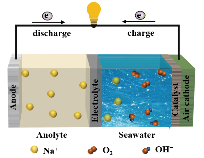
Na-based seawater batteries are expected to become a new-generation of energy storage device due to its advantages of environmental friendliness, high energy density, and abundant and easy availability of seawater. Its working principle is that the conversion between the chemical energy and the electrical energy is achieved through redox reaction when seawater is considered as the electrolyte. In this review, the electrochemical principle, and design and optimization strategy of battery structure of Na-based seawater batteries are summarized. The latest research progress of Na-based seawater batteries is reviewed. Finally, the challenges to overcome the performance improvement and commercialization of Na-based seawater batteries are discussed, and the future development directions of the batteries are forecasted. The review provides the theoretical guidance for the development of Na-based seawater batteries, and then promotes Na-based seawater batteries support for major national needs such as the deep-sea energy supply and extremely environmental-energy source.

Cite this article

Niu Wenhui , Zhang Da , Zhao Zhengang , Yang Bin , Liang Feng . Development of Na-Based Seawater Batteries: “Key Components and Challenges”[J]. Progress in Chemistry, 2023 , 35(3) : 407 -420 . DOI: 10.7536/PC220902

Contents

1 Introduction
2 The introduction of Na-based seawater battery
2.1 The concept of Na-based seawater battery
2.2 The electrochemical principle of Na-based seawater battery
2.3 The characteristics of Na-based seawater battery
2.4 Battery design and optimization
3 Key components and challenges of Na-based seawater battery
3.1 Anode
3.2 Organic electrolyte
3.3 Solid electrolyte
3.4 Catalysts
4 Conclusion and prospect

1 Introduction

With the rapid development of economy, people's demand for energy is increasing, which leads to the depletion of limited traditional energy such as coal, oil and natural gas, and causes environmental problems such as haze, glacier melting and global warming[1,2]. Therefore, optimizing the energy structure and developing efficient low-carbon clean energy is an important direction of sustainable development in the world today. Electrochemical energy conversion and storage devices, represented by batteries, are of great practical significance to reduce fossil fuel consumption and environmental pollution[3].
In recent years, the production capacity of lithium-ion batteries with high specific energy and long cycle life has been expanding due to the demand of electric vehicle market. However, the pursuit of higher energy density and lower cost in the electric vehicle market has led to technological research in the post-lithium-ion battery era[4]. At the same time, due to the scarcity, high cost and safety problems (cobalt is toxic) of lithium and cobalt, which are the core elements of lithium-ion batteries, their practicability is limited[5,6]. Based on this, it is urgent to develop new energy storage devices to replace lithium-ion batteries, such as sodium-ion batteries, metal-air batteries and fuel cells[7][8][9]. Among them, sodium-based seawater batteries use seawater, sodium-based materials and dissolved oxygen in seawater as electrolyte, anode and cathode active materials respectively. Because of its high energy density, low cost and environmental friendliness, it is expected to become a new generation of green energy leader in deep-sea exploration and other fields[10,11].
Sodium-based seawater battery uses seawater (containing sodium ions and dissolved oxygen) as catholyte to realize the conversion of chemical energy and electric energy through redox reaction[3,12]. The use of seawater significantly reduces material and manufacturing costs. At the same time, the open structure of the cathode and the circulating seawater promote the heat transfer of the battery and reduce the burden of heat management, thus improving the safety and cycle life of the battery[13]. To sum up, sodium-based seawater battery is considered to be a promising energy conversion and storage device, but the related theoretical research and technology are still in the initial stage of exploration. In order to promote the commercialization of sodium-based seawater battery, the electrochemical principle, battery structure design and optimization strategy are summarized in this paper.Including sodium-based anode, organic electrolyte, solid electrolyte and cathode catalyst. The existing problems of the battery were analyzed and the corresponding solutions were proposed. The challenges to be overcome in the commercialization of the battery were discussed. Finally, the development direction of sodium-based seawater battery is predicted.

2 Introduction of Sodium-Seawater Battery

2.1 Concept of sodium-seawater cell

Seawater can be used as a sodium – seawater battery catholyte because of its wide source and high sodium ion (Na+) concentration (0.47 M) and ionic conductivity (50 mS·cm-1)[14~16]. The sodium-based seawater battery has a similar battery structure to the sodium-air battery, and the difference is that the former uses seawater as the catholyte, as shown in Figure 1. The sodium-based seawater battery is composed of an air cathode (including a catalyst and a current collector), seawater, a solid electrolyte (NASICON), an organic electrolyte, and a sodium material[17]. The sodium-based material and the organic electrolyte form the anode chamber, the air cathode and the seawater form the cathode chamber, and the solid electrolyte separates the anode chamber from the cathode chamber. The working principle is as follows: upon discharge, Na+ is transferred from the anode chamber to the air cathode, where readily soluble sodium hydroxide (NaOH) is generated at the interface between the seawater electrolyte (dissolved oxygen) and the electrocatalyst through the oxygen reduction reaction (ORR). When charging, oxygen evolution reaction (OER) occurs on the cathode side to store electrical energy, that is, Na+ in seawater is transported to the anode and deposited on the surface of the anode material[16,18].
图1 钠基-海水电池工作示意图

Fig. 1 Working diagram of Na-based seawater battery

2.2 Electrochemical principle of sodium-seawater cell

According to the working principle of sodium-based seawater battery, its electrochemical process is as follows:
Anode :Na↔Na++e-Eθ=2.71 V.
Cathode :1/4O2+1/2H2O+e-↔OH-.
Eθ=-0.77 V
The overall reaction :Na(s)+1/4O2(g)+1/2H2O(l)↔NaOH(aq)Eθ=3.48 V
Since chloride ions (Cl-) account for about 0.54 M in seawater, at a certain potential and pH, Cl- participates in the redox reaction to produce hypochlorite or precipitate chlorine (Equation 1 – 2). Fig. 2a shows the thermodynamic Pourbaix of simulated seawater, showing the electrochemical behavior of oxygen/chlorine in seawater at different potentials (vs SHE) and pH. Dissolved oxygen in seawater is easily reduced during the discharge process of sodium-based seawater battery. In the charge process, whether in alkaline or acidic conditions, the OER is better than the formation of hypochlorite or chlorine evolution in thermodynamics, but when the overpotential of catalytic OER is greater than 900 mV, the Cl- will be oxidized to form hypochlorite. Therefore, in order for the sodium-based – seawater battery to operate properly, it should be ensured that the overpotential of the catalyst to catalyze OER under alkaline conditions is less than 490 mV to avoid the generation of hypochlorite[16]. Fig. 2b is a kinetic Pourbaix of simulated seawater, showing the electrochemical behavior of oxygen/chlorine in seawater at different potentials (vs SHE) and pH. From the figure, it can be seen that the Cl- will inhibit the reaction kinetics of the sodium-seawater cell. Specifically, when ORR occurs, the strongly adsorbed Cl- in seawater adheres to the surface of the catalyst, thus covering the active sites of the catalyst and inhibiting the adsorption of oxygen, resulting in slow ORR kinetics[19,20]. In addition, the adsorption of Cl- hinders the cleavage of the O — O bond and induces a two-electron ORR process, as shown in Equations 3 and 4. The H2O2 or radicals formed at the multiphase interface attack the catalyst and the metal anode, thereby reducing the durability of the catalyst[21,22]. In the charging process, the formation of hypochlorite or chlorine is a two-electron reaction involving a single intermediate, while OER is a four-electron reaction involving three intermediates. The two reactions have similar active sites and reaction paths, so OER catalysts are more conducive to Cl- two-electron oxidation[16]. To sum up, a catalyst should be designed that can inhibit the Cl- adsorption and oxidation and the four-electron reaction path occurs.
图2 模拟海水的热力学Pourbaix图(a)和动力学Pourbaix图(b)[16]

Fig. 2 (a) Simulated Pourbaix diagram of seawater about thermodynamics. (b) Simulated Pourbaix diagram of seawater about kinetics[16]

Cl- + 2OH- - 2e- → ClO- + H2O (碱性条件)
Cl- + H2O - 2e-→ HClO + H+ 或 Cl- - 2e- → Cl2 (酸性条件)
O2+ H2O + 2e- → H O 2 - + OH- (碱性条件)
O2 + 2H+ + 2e- → H2O2 (酸性条件)

2.3 Characteristics of sodium-base seawater battery

According to the structure and working principle of the sodium-based seawater battery, the battery has the following characteristics: (1) seawater is used as a catholyte, and a device for storing the electrolyte is not needed, so that the manufacturing cost is reduced, the weight of the battery is reduced, and the mass energy density is improved; (2) The flowing seawater can reduce the polarization of the reactant to the electrode, so that the electrode reaction is stable and the electrode efficiency is improved; (3) the open battery system and the flowing seawater take away the heat generated when the battery works, thereby facilitating the thermal management of the battery system; And (4) seawater which is rich in resources and easy to obtain is used as the catholyte, thereby reducing the cost of the battery[23,24].

2.4 Battery design and optimization

2.4.1 Catalyst evaluation

Like other metal-air batteries, ORR and OER are the two key processes of sodium-based seawater[25,26]. Where ORR is a multi-electron and proton coupled electrochemical reaction. In this process, oxygen molecules adsorbed on the electrode surface are reduced to H2O (acidic) or OH- (alkaline) via a four-electron reaction path, or to H2O2 (acidic) or HO 2 - (alkaline) via a two-electron reaction path[27,28]. In addition, Cl- is easily adsorbed on the active sites of the catalyst, which hinders the cleavage of O — O bonds, thus reducing the activity of the catalyst[29]. For OER, which is considered to be the rate-limiting step of sodium-based seawater batteries, the reaction process is extremely complex and closely related to the structure of the catalyst surface[30~32]. Nowadays, according to the adsorbate evolution mechanism (AEM), OER involves a variety of oxygen reaction intermediates (*O, *OOH, and *OH), and the binding energies of the intermediates follow a proportional relationship of ΔGOOH=ΔGOH+3.2±0.2 eV and are linearly correlated, which results in a minimum theoretical overpotential of 0.37 V[33,34]. Therefore, there is an urgent need for catalysts with high catalytic activity to accelerate the OER process. The OER process of sodium-based seawater battery is a four-electron reaction involving three intermediates, while the oxidation of Cl- is a two-electron reaction involving a single intermediate, so there is a competitive relationship between the oxidation of Cl- in seawater and OER, and the Cl- oxidation reaction is easy to occur when the catalyst with OER overpotential greater than 490 mV is used. Generally, Pt/C and RuO2 are catalysts with high catalytic activity for ORR and OER, respectively, but the high cost and scarcity of noble metals limit their wide application in sodium-based seawater batteries[35,36]. In addition, Pt-based materials are highly sensitive to Cl- and easily react with them to form soluble chloro complexes (such as PtCl 4 2 -), thus reducing the structural stability of noble metal catalysts[37,38]. Therefore, non-noble metal catalysts should be designed that are efficient and selective for oxygen/chlorine catalysis.
In addition, the actual discharge voltage plateau of the battery is lower than its standard voltage plateau, while the charge voltage plateau is higher than the standard voltage plateau due to the internal voltage losses of the battery, such as activation polarization, ohmic polarization, and concentration polarization[39]. To sum up, the sodium-based seawater battery catalyst should have the following functions: (1) shorten the reaction path, reduce the reaction activation energy, and accelerate the reaction rate; (2) large specific surface area, hierarchical porous structure and high porosity; (3) excellent mechanical and chemical stability; (4) a highly conductive network (good conductivity) promotes electron transfer; (5) Strong oxygen/chlorine selectivity[40~42].

2.4.2 Battery evaluation

In addition to the selection of catalysts, battery evaluation is also one of the important links in the research and development of high-performance batteries. Battery evaluation metrics include electrochemical performance, cost, and safety. Electrochemical properties include overpotential, capacity, power/energy density, and cycle performance. The overpotential is related to the catalyst. Specifically, the ORR/OER corresponds to the discharge/charge curve of the battery. The weaker the ability of the catalyst to reduce the activation energy of the reaction, the greater the overpotential of the battery. For example, the hybrid sodium-air batteries assembled by Liang et al. Using different catalysts (MOF-NCNTs, Pt/C, and RuO2) showed different overpotentials due to the different ability of the catalysts to reduce the reaction activation energy[11]. The capacity of the battery is related to the solid electrolyte and organic electrolyte, in which the solid electrolyte and electrolyte with high ionic conductivity and stability can reduce the interface impedance, accelerate the Na+ transfer, improve the utilization efficiency of the anode, and make the battery show higher discharge capacity[43][44]. The energy density and power density of the battery are related to the catalyst and solid electrolyte. The efficient catalyst can reduce the activation energy, accelerate the reaction rate, and make the battery have a higher discharge voltage, thereby improving the power density of the battery[45]. The highly conductive solid electrolyte can accelerate the discharge process and improve the energy/power density of the battery. Cycle performance is the most important evaluation standard of rechargeable batteries. At present, the optimal cycle performance of sodium-based seawater batteries can reach 600 times, but it still can not meet the practical application[46]. As for the battery cost, the energy cost of lithium-ion and sodium-ion batteries is estimated to be $1600~1800 kW·h-1和$ 1400~1600 kW·h-1 at the current material price, while the energy cost of sodium-air batteries is only $100~200 kW·h-1. In addition, the sodium-based seawater battery uses cheap seawater as catholyte, so its cost is lower[47,48]. Cathode open structure and circulating seawater can effectively accelerate the heat transfer of the battery, thus reducing the burden of heat management and significantly improving the safety of the battery in application.

2.4.3 Battery Structure Design

In order to promote the practical application of rechargeable sodium-based seawater batteries, researchers have designed and optimized the battery structure. First, Kim's group designed a pouch cell (Figure 3A), in which the anode chamber consists of a nickel current collector and an organic electrolyte, the exposed conductive film is connected to the carbon felt cathode current collector, and the cathode is immersed in a beaker filled with seawater[13]. The battery has the advantages of simple assembly and low cost, but its low safety and poor cycle performance make it difficult to be applied on a large scale. Fig. 3B shows a coin cell in which a solid electrolyte (NASICON) is fixed to an open circular cover made of polypropylene material, sodium metal is attached to a circular stainless steel gasket filled with an organic electrolyte and sealed with epoxy glue, and finally assembled with a cathode current collector[49]. The battery can be uniformly evaluated electrochemically as a coin cell, but it is difficult to prepare and transport on a large scale due to the rigidity (fragility) of the NASICON electrolyte. In order to solve the above problems, the researchers designed a rectangular cell (Figure 3C), in which 12 rectangular NASICONs were fixed on a stainless steel mesh, and then sodium biphenyl was injected to form an anode chamber, which was sealed with carbon cloth[50].
图3 (a)袋式电池[13],(b)纽扣式电池,(c)矩形电池,(d)棱柱形电池实物图[51]

Fig. 3 The physical map of (a) pouch cell[13], (b) coin cell, (c) rectangular cell, and (d) prismatic cell[51]

The battery can maximize the space utilization of the battery, and at the same time, the low cost and processability provide possibilities for its application, but the energy and power density of the battery still can not meet the needs of practical applications. In order to improve the power density, Kim's team developed a prismatic battery, as shown in Figure 3D. Its structure is similar to that of a rectangular battery, but the difference is that the anode chamber uses a larger area of NASICON and the cathode current collector is designed to resist seawater corrosion[51]. The cell has high energy density (242 Wh·L-1) and power density (5.8 mW·cm-2), but its cycling stability and energy efficiency are poor.
To sum up, although the battery performance can be improved through the battery structure design, there is still a gap from the practical application. It is necessary to further explore the impact of various component materials on the battery, optimize the internal structure and space of the battery, and improve the utilization efficiency, so as to design a low-cost, high-performance and long-life battery. Based on this, this paper will summarize the latest progress of anode part, organic electrolyte, solid electrolyte and cathode catalyst to help the commercialization process of sodium-based seawater battery.

3 Key Components and Challenges of Sodium-Seawater Battery

3.1 Anode part

Sodium metal anode has a low redox potential (− 2.71 V vs SHE) and a high theoretical capacity (V vs SHE), but it faces the problems of uncontrolled dendrite growth, unstable solid electrolyte interface layer (SEI), and volume expansion during cycling, resulting in poor cycling performance, low capacity, and low coulombic efficiency[52]. In addition, the sodium dendrite pierces the diaphragm and causes short circuit of the battery, and even the seawater electrolyte reaches the anode and reacts with sodium metal, causing accidents such as explosion and fire[53]. An effective strategy to solve the above problems is to form a stable SEI layer on the anode surface and inhibit the growth of sodium dendrites. In theory, anode materials for sodium-ion batteries with redox potential close to the E N a + / N a, high chemical stability and high reversible capacity can be used in sodium-based seawater batteries, such as insertion materials, alloying materials and conversion materials[54,55][56].

3.1.1 Sodium-free anode (Gr/Cu current collector)

The uneven deposition of sodium metal on the copper foil current collector is easy to cause the growth of sodium dendrite, which leads to the reduction of battery cycle performance. In order to inhibit the growth of dendrites, sodiophilic materials can be introduced on the surface of the anode current collector, thereby reducing the nucleation barrier of Na+ and helping the uniform deposition of Na+ on the anode. For example, Choi et al. Prepared graphene-coated copper composite (Gr/Cu) by chemical vapor deposition and used it in sodium-free anode sodium-based seawater battery[57]. In order to explore the sodium dendrite growth on Cu and Gr/Cu current collectors, the cell (Cu or Gr/Cu | 1 M NaOTF/DME | Na) was tested at constant current density (3.25 mA·cm-2), and the sodium dendrite growth process was recorded by time-lapse camera. As shown in Figure 4A, no dendrite is formed on the Cu current collector in the first 50 min, while sharp needle-like sodium dendrites appear and grow rapidly to the opposite sodium electrode in the last 50 min. The irregular growth of sodium dendrites in the full battery will pierce the separator, resulting in short circuit of the battery and potential safety hazards. However, the Gr/Cu current collector can significantly delay the appearance of sodium dendrites (90 min) and slow down the growth rate of sodium dendrites (Fig. 4F). This is because the corrugated surface of the heterogeneous interface of the Cu current collector can reduce the nucleation energy barrier of Na+, which is conducive to the formation of smaller sodium dendrites (Fig. 4C). The monolayer graphene is covered on the Cu foil (Figure 4D), which can not only eliminate the chemical instability of the Cu current collector, but also maintain the morphology of the Cu current collector. It can be seen from fig. 4E that the corrugated Cu foil is covered by graphene with carbon hexagons, so that the Gr/Cu current collector interface becomes uniform, thereby delaying the appearance time of sodium dendrites and reducing the number of dendrite nuclei. In the electrochemical test, the sodium nucleation overpotential is represented by the difference between the potential drop value (<0 V vs Na+/Na) and the voltage plateau of the sodium deposition process. In order to study the effect of different current collectors on the sodium nucleation overpotential, galvanostatic plating and stripping tests were conducted (Figure 4G). Compared with the Cu current collector, the symmetrical cell with Gr/Cu as the current collector showed a lower nucleation overpotential (40 mV) and a more stable sodium plating/stripping process, and its coulombic efficiency remained unchanged after 200 cycles (150 H). This is due to the fact that the uniform interface of Gr/Cu current collector in the electrochemical reaction can provide abundant nucleation sites as well as weaken the volume change of the sodium plating/stripping process. In addition, the full cell with Gr/Cu as the current collector (Na | NASICON | seawater) has a longer cycle life. Fig. 4h is a schematic diagram of the charge-discharge structure of the battery. Compared with the Cu current collector, the metal sodium on Gr/Cu has a larger grain size, fewer crystal nuclei, and a smooth surface. This indicates that the uniform surface of Gr/Cu current collector is beneficial to control the nucleation rate of sodium metal, thus forming a uniform and smooth sodium metal deposition layer, which is conducive to the reversible anodic sodium deposition/stripping process.
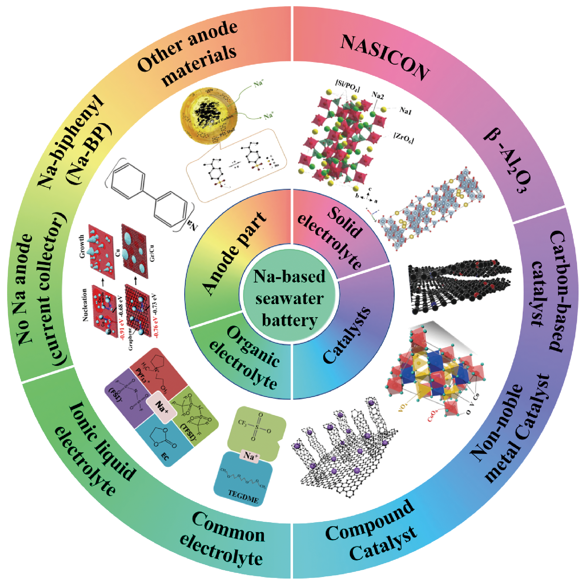
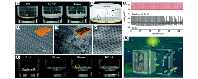
图4 (a)Cu集流体上钠枝晶生长的延时照片,黄色圆圈表示钠枝晶出现;(b)电池设计和钠枝晶生长示意图;(c)Cu和(d)Gr/Cu集流体的俯视扫描电子显微镜图像,插图表示集流体的示意图;(e)Gr/Cu集流体的高分辨率扫描隧道显微镜表面图像;(f)Gr/Cu集流体上钠枝晶生长的延时照片,黄色圆圈表示钠枝晶出现;(g)以Gr/Cu(红线)和Cu(黑线)为集流体的计时电位法图;(h)以Cu和Gr/Cu为集流体的钠基-海水电池充放电结构示意图[57]

Fig. 4 (a) Time-lapse photographs of Na dendrite growth on the Cu current collector, the yellow circle shows the appearance of Na dendrite. (b) Schematic of the battery design and Na dendrite growth, top-view scanning electron microscope (SEM) images of (c) Cu and (d) Gr/Cu current collectors, the insets represent current collectors. (e) High resolution scanning tunneling microscope (STM) topography image of Gr/Cu current collector. (f) Time-lapse photographs of Na dendrite growth on the Gr/Cu current collector. the yellow circle shows the appearance of Na dendrite. (g) Chronopotentiometry plots of Gr/Cu (red line) and Cu (black line) current collectors. (h) Schematic diagram of charge-discharge of Na-base seawater battery with Cu and Gr/Cu current collectors[57]

3.1.2 Sodium biphenyl (Na-BP-DEGDME) (sodium-biphenyl-diethylene glycol dimethyl ether)

Sodium metal is easy to form dendrites in the deposition/stripping process, which increases the possibility of battery short circuit, thus causing potential safety hazards. At the same time, the shape and volume of the sodium anode are prone to change during battery cycling, resulting in the decomposition of the SEI layer and the formation of a new SEI layer on the newly exposed sodium surface. In this process, sodium and electrolyte are continuously consumed, which reduces the energy efficiency of the battery[58]. In addition, the high reactivity of sodium metal with common electrolytes leads to the precipitation of H 2 by side reactions, which degrades the capacity and cycle performance of sodium-based seawater batteries[59]. In order to solve the above problems, Kim et al. Assembled a sodium-based seawater battery using Na-BP-DEGDME as the anode[59]. As shown in Figure 5A, the Na-BP-DEGDME molecule with high electronic/ionic conductivity acts as an intermediary/carrier of Na+ and electrons, which is beneficial to reduce the sodium deposition potential, inhibit the precipitation of H2 and the growth of needle-like sodium dendrites, so that the battery exhibits excellent capacity retention and cycling stability (400 H) (Figure 5B). As shown in Fig. 5C – e, our research group prepared Na-BP-TEGDME (sodium-biphenyl-tetraethylene glycol dimethyl ether) and used it in a hybrid sodium-air battery, which exhibited excellent cycling stability (500 cycles), round-trip efficiency (93.26%), and power density (621 mW·g-1)[35].
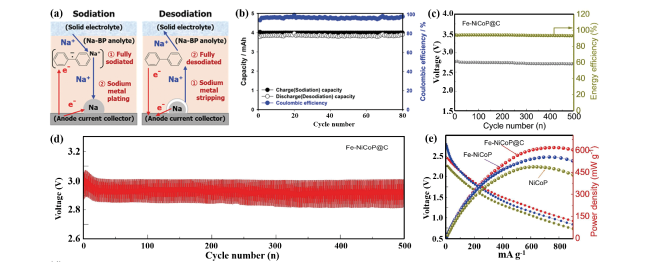
图5 (a)Na-BP-DEGDME阳极电池充放电过程示意图;(b)Na-BP-DEGDME阳极钠基-海水电池循环性能图[59];(c)在0.01 mA·cm-2下,Na-BP-TEGDME阳极电池的循环性能和能量效率图;(d)在0.01 mA·cm-2下,Na-BP-TEGDME阳极电池的恒电流循环曲线;(e)使用不同催化剂和Na-BP-TEGDME阳极电池的能量密度图[35]

Fig. 5 (a) Schematic diagram of charging and discharging process of Na-BP-DEGDME anode battery. (b) Cycle performance of Na-based seawater battery with Na-BP-DEGDME anode[59]. (c) Cycling performance and energy efficiency of battery with Na-BP-TEGDME anode at 0.01 mA·cm-2. (d) Galvanostatic cycling of battery with Na-BP-TEGDME anode at 0.01 mA·cm-2. (e) Power density of batteries with different catalysts and Na-BP-TEGDME anode[35]

3.1.3 Other anode materials

Hard carbon (HC) can be used as a sodium-based – seawater battery anode because of its working potential (vs Na+/Na) close to that of metallic sodium and high reversible capacity. The feasibility of HC as the anode of sodium-based seawater battery was proved by half-cell (Na | HC) and full-cell (HC | seawater) charge-discharge experiments and simulations[13]. Lim et al. Used HC-polystyrenesulfonic acid (HC-PSS) anode for sodium-seawater battery, and the reversible specific capacity of HC-PSS anode at 0.5 and 1 C current density was 383.2 and 295.5 mAh·g-1, respectively, and the discharge capacity and coulombic efficiency of the whole battery were 382 mAh·g-1 and 99.5%, respectively, after 100 stable cycles at 0.5 C, which proved that HC was an ideal anode material for sodium-seawater battery[60].
High capacity characteristic conversion-Alloy materials are prone to volume expansion during battery cycling, resulting in the continuous formation of SEI layer, and the Na+ provided by the cathode is continuously consumed, resulting in capacity reduction[61,62]. However, the sodium-based – seawater battery has an open cathode structure, and seawater can continuously supply Na+ to alleviate the capacity fading. Therefore, the high capacity characteristic conversion-alloy materials can be used in sodium-based seawater batteries.
The Gr/Cu current collector and Na-BP anode reduced the sodium deposition potential and inhibited the dendrite growth, thereby improving the battery life. The HC material contains a large number of defects, which is beneficial to the storage of sodium ions with a large radius and improves the reversible capacity of the battery. The open cathode structure of sodium-based seawater battery makes the battery with conversion-alloy material as the anode show excellent cycle stability. At the same time, the conversion-alloy material does not involve sodium metal in the battery manufacturing process, so it can be assembled in a low humidity environment, which significantly reduces the cost of safety measures and the purchase of sodium metal.

3.2 Organic electrolyte

As an important part of sodium-based seawater battery, organic electrolyte is closely related to the stability of the anode chamber. The ideal organic electrolyte should have high chemical stability, low cost and environmental friendliness. However, the electrolyte composed of highly volatile and flammable organic carbonate as solvent is easy to leak and cause spontaneous combustion or explosion. In addition, the electrolyte containing the conductive salt sodium hexafluorophosphate (NaPF6) is prone to hydrolyze and release the toxic gas HF. Organic carbonate electrolyte usually shows a low electrochemical window, which is prone to side reactions to produce H2 during use, resulting in a decrease in the stability of batteries, thereby shortening the cycle life of batteries[46]. Therefore, in order to meet the requirements of high energy density and long cycle of sodium-based seawater batteries, it is essential to select organic electrolytes with high ionic conductivity and chemical stability. As shown in Table 1, the electrolytes used in sodium-based seawater batteries and their electrochemical performance are summarized in this paper.
表1 使用有机电解液对应的钠基-海水电池电化学性能的对比

Table 1 Comparison of electrochemical performance of Na-based seawater batteries with organic electrolyte

Anodic electrolyte Anode Applied current Discharge capacity
(mAh·g-1)
Cyclic performance ref
1 M NaClO4 in EC/PC HC 0.05 mA·cm-2 115 30 63
1 M NaCF3SO3 in TEGDME HC 0.05 mA·cm-2 126 100 63
ILE-EC HC 0.3 mA·cm-2 290 600 46
1 M NaClO4 in EC/DMC (1∶1) with
1 vol% FEC
PC 1.0 A·g-1 973 80 67
1 M NaClO4 in EC/DMC (1∶1) Sn-C 0.05 mA·cm-2 300 30 68
Kim et al. Explored the effect of two electrolytes, 1 M NaCF3SO3 dissolved in TEGDME and 1 M NaClO4 dissolved in EC/PC (ethylene carbonate/propylene carbonate), on battery performance[63]. As shown in Figure 6A, the battery with the former electrolyte has a higher discharge capacity (126 mAh·g-1) at the same current density, indicating that the battery has a higher utilization of active material. At the same time, the battery using the former electrolyte can cycle stably for 100 times, and the capacity retention rate is as high as 90%, while the battery using the latter electrolyte has a significant capacity fading after 30 cycles (Fig. 6B), indicating that the battery using 1M NaCF3SO3 dissolved in TEGDME electrolyte has better cycle stability.This is due to the formation of a thin and stable SEI layer induced by TEGDME, while the latter induced the decomposition of fluorine from PVDF by EC/PC in the electrochemical reaction, and the reaction of fluorine and sodium formed a thicker and less conductive SEI layer (NaF). However, 1 M NaCF3SO3/TEGDME electrolyte is prone to side reaction and gas evolution during battery operation[64]. Therefore, the researchers designed an ionic liquid electrolyte with high thermal stability and low flammability[65,66]. For example, Kim et al[46].
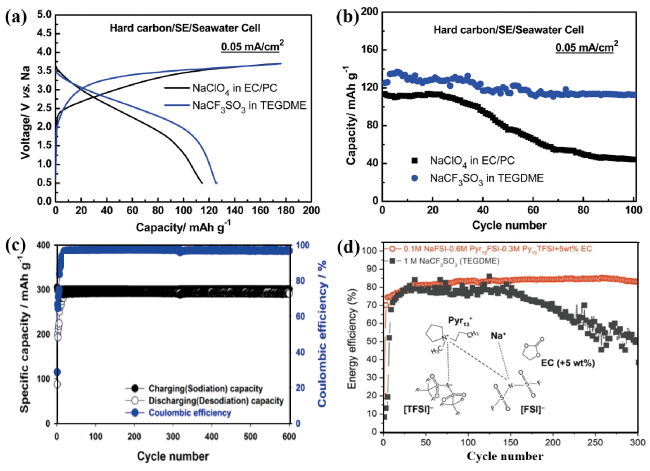
图6 海水电池使用两种电解液(1 M NaCF3SO3溶于TEGDME,1 M NaClO4溶于EC/PC)的(a)充/放电曲线和(b)循环性能[63];(c)使用电解液ILE-EC的钠基-海水电池容量保持率[46];(d)使用电解液ILE-EC和1 M NaCF3SO3溶于TEGDME的钠基-海水电池循环性能[56]

Fig. 6 (a) Charge-discharge curves and (b) Cycling performance of the seawater battery with 1 M NaCF3SO3 in TEGDME and 1 M NaClO4 in EC/PC electrolyte[63]. (c) Capacity retention of Na-based seawater battery with ILE-EC electrolyte[46]. (d) Cycling performance of Na-based seawater battery with ILE-EC and 1 M NaCF3SO3 in TEGDME electrolyte[56]

An ionic liquid electrolyte (ILE-EC) composed of Pyr13TFSI(0.3 M), NaFSI (0.1 M), and 5 wt% EC was used in the sodium-based – seawater battery, which has high energy efficiency, discharge capacity (290 mAh·g-1), and coulombic efficiency (98%) at different current densities (Figure 6 C). As shown in Figure 6 d, the battery with ILE-EC exhibits superior reversible capacity, capacity retention, and energy efficiency compared with the battery with electrolyte (1 M NaCF3SO3/TEGDME), due to the wide electrochemical stability window of Pyr13TFSI in ILE-EC and the formation of SEI layer promoted by EC.
To sum up, an ideal organic electrolyte should have the characteristics of high chemical stability, wide electrochemical window and promoting the formation of SEI layer. However, the organic electrolyte of sodium-based seawater battery often uses flammable lipids as solvents, which will cause potential safety hazards when the battery is short-circuited or thermally out of control. At the same time, lipid electrolyte can not effectively inhibit the growth of sodium dendrite, thus reducing the cycle stability of the battery. Compared with lipid organic electrolytes, ionic liquids have higher ionic conductivity, thermal stability and safety. Therefore, sodium-based seawater batteries using ILs exhibit excellent cycling stability, high capacity, and high energy efficiency. However, the high production cost of ionic liquids limits their commercialization, so reducing the production cost is the key to solve this problem.

3.3 Solid electrolyte

The function of that solid electrolyte is to separate the anode and cathode compartment of the cell to prevent short circuiting of the cell while allow Na+ to travel between the two electrodes. In order to obtain high-performance sodium-based seawater batteries, solid electrolytes should have the following characteristics: high ionic conductivity at room temperature, good chemical stability, sodium ion selectivity, wide electrochemical window, good mechanical stability and interfacial compatibility[56,69,70]. According to the structure and chemical composition, sodium-based solid electrolytes can be divided into β-alumina, NASICON-type, polymer-type, and sulfide-type. β-Alumina and NASICON-type solid electrolytes have attracted much attention because of their high ionic conductivity, excellent chemical and mechanical stability. In this section, two sodium-ion conducting ceramic electrolytes, β-alumina and NASICON, will be highlighted, and their applications in sodium-seawater batteries will be reviewed.

3.3.1 β-alumina solid electrolyte

β-alumina electrolyte was first reported in 1967[71~73]. As shown in Fig. 7 a, β-alumina has two crystal structures of hexagonal β-alumina (β-Al2O3) and rhombic β ″ -alumina (β″-Al2O3), both of which are composed of spinel layers composed of [AlO4] tetrahedra and [AlO6] octahedra and two sodium-oxide layers stacked alternately[74,75]. Among them, β″-Al2O3 possesses higher ionic conductivity (1.4×10⁻²S·cm-1) due to its high sodium content, which exhibits excellent cycling stability when used in sodium-sulfur batteries[76]. When the β″-Al2O3 solid electrolyte was used in the sodium-based – seawater battery, by comparing the X-ray diffraction (XRD) patterns of β″-Al2O3 before and after cycling, it was found that the AlOOH phase was formed after 10 cycles, resulting in a decrease in the cycling stability of the battery (Figure 7B)[43]. This is due to the entry of water molecules, H+ and H3O+ into the β″-Al2O3 lattice, which destroys the β″-Al2O3 structure and hinders the Na+ transfer in the electrolyte, resulting in the decrease of its conductivity[77~80].
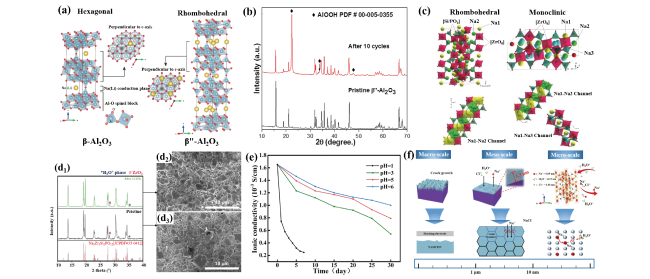
图7 (a)β-Al2O3和β″-Al2O3固体电解质的晶体结构[75];(b)钠基-海水电池循环前后β″-Al2O3固体电解质的XRD图[43];(c)NASICON(Na3Zr2Si2PO12)固体电解质的晶体结构和离子迁移路径[83];(d)NASICON固体电解质在海水浸泡前后的XRD图和SEM图[13];(e)NASICON固体电解质在不同pH值溶液中浸泡不同时间的离子电导率;(f)NASICON固体电解质在不同pH值酸性溶液中的腐蚀机理[86]

Fig. 7 (a) Crystal structures of the β-Al2O3,and β″-Al2O3 solid electrolytes[75]. (b) X ray diffraction (XRD) patterns of β″-Al2O3 solid electrolytes before and after cycling of Na-based seawater battery[43]. (c) Crystal structures and ion transport paths of NASICON (Na3Zr2Si2PO12) solid electrolytes[83]. (d) XRD patterns and SEM images of NASICON solid electrolytes before and after immersion in seawater[13]. (e) Ionic conductivity of NASICON solid electrolytes with immersion different time in solutions with different pH values. (f) Corrosion mechanism of NASICON solid electrolyte in acidic solutions with different pH values[86]

3.3.2 NASICON-type solid electrolyte

NASICON-type solid state electrolyte was first proposed by Goodenough et al. In 1976, and its general formula is Na 1 + x Zr2SixP3-xO12(0≤x≤3), which is formed by partial substitution of P by Si when the parent NaZr2P3O12 is in excess of sodium[81]. There are rhombic and monoclinic phases of Na3Zr2Si2PO12 with good conductivity (Fig. 7 C), in which the corner-sharing tetrahedron composed of SiO4 and PO4 and the ZrO6 octahedron structure form three-dimensional (3D) channels favorable for Na+ transport[82,83]. The Na1 site located between the two ZrO6 octahedra in the rhombic structure and the Na2 site located between the two structural bands constitute a three-dimensional channel (Na1-Na2), and the Na2 site can accommodate 3 mol Na+, which is beneficial to Na+ transport. However, in the monoclinic structure, the Na2 site is split into Na2 and Na3 sites to form Na1-Na2 and Na1-Na3 channels due to the lattice distortion caused by the replacement of PO4 tetrahedra by larger SiO4 tetrahedra. NASICON-type solid electrolytes with 3D Na+ channels and high ionic conductivity have been widely used in sodium-metal chloride batteries and CO2 sensors[56]. In order to evaluate the feasibility of NASICON electrolyte used in sodium-based seawater battery, Hwang et al. Immersed NASICON electrolyte in seawater at room temperature for 1440 H, and found that the phase and morphology of NASICON did not change before and after immersion in seawater through XRD and SEM (Fig. 7d), indicating that NASICAN electrolyte has excellent structural stability in seawater[13]. In addition, the sodium-based seawater battery assembled by Kim et al. Using NASICON electrolyte can be stably cycled for 600 times, and the morphology, phase and ionic conductivity of NASICON electrolyte do not change after cycling, which further proves the feasibility of NASICON-based electrolyte for sodium-based seawater battery[46][46,84,85]. As shown in Fig. 7e, f, our research group tested the stability of NASICON electrolyte in acidic solution with different pH values, and found that with the decrease of solution pH value, the proton exchange rate of H3O+ and Na+ increased, and the decrease of Na+ concentration in the lattice led to the contraction of PO4 tetrahedron and the formation of H3O+-NASICON phase, which reduced its conductivity[86].
In summary, the NASICON solid electrolyte is more stable than the β″-Al2O3 in the sodium-based seawater battery. The chemical stability and ionic conductivity of NASICON solid electrolyte determine the power density, cycle stability, safety performance and service life of sodium-based seawater battery, which is very important for the development of the battery system. However, NASICON solid electrolyte still faces the problems of poor interfacial wetting and low ionic conductivity. At the same time, there are few reports on the stability test of NASICON solid electrolyte with organic electrolyte and seawater at high current density, so the structural stability of NASICON solid electrolyte in practical application needs to be discussed. Based on this, the research and development of NASICON solid electrolyte with high conductivity and high stability is of great practical significance for the development of high energy density batteries.

3.4 Catalyst

As the most important part of the sodium-based seawater battery, the catalyst determines the energy efficiency and power density of the battery. As the two main reactions of sodium-based seawater batteries, ORR and OER have slow kinetic processes, resulting in large overpotential, poor cycle stability and low energy density[87~89]. Therefore, it is essential to use efficient catalysts that accelerate the reaction rate and reduce the overpotential. In general, noble metal catalysts exhibit excellent ORR and OER catalytic performance, but their high cost and scarcity seriously hinder their large-scale application[27,90,91]. In addition, noble metal catalysts are often single reaction (ORR or OER) catalysts, which cannot efficiently catalyze both ORR and OER. Therefore, it is urgent to develop efficient and inexpensive bifunctional catalysts.
At present, bifunctional electrocatalysts can be divided into three categories: carbon-based catalysts, non-noble metal-based catalysts, and composite catalysts. This section summarizes the catalysts currently used in sodium-based – seawater batteries, as shown in Table 2.
表2 不同催化剂对应的钠基-海水电池电化学性能对比

Table 2 Comparison of electrochemical performance of Na-based seawater batteries with different catalyst

Catalysts Anode Electrolyte Applied current Voltage
gap (V)
Discharge capacity (mAh·g-1) Cyclic performance ref
CMO HC 1 M NaCF3SO3 in TEGDME 0.01 mA·cm-2 ~0.53 ~190 100 95
3D macroporous carbon sponge Na 1 M NaCF3SO3 in TEGDME 0.025 mA·cm-2 0.46 - 100 102
N,S-doped carbon nanospheres Na 1 M NaCF3SO3 in TEGDME 5 mA·g-1 0.56 - 100 103
Pine pollen carbon (PPC) PPC 1 M NaCF3SO3 in TEGDME 50 mA·g-1 ~195 100 93
Activated carbon cloth Na 1 M NaCF3SO3 in TEGDME 0.13 mA·cm-2 ~0.6 - 80 43
Co3V2O8 Na 1 M NaCF3SO3 in TEGDME 0.1 mA·cm-2 ~0.9 - 20 96
S-rGO-CNT-Co Na 1 M NaCF3SO3 in TEGDME 0.01 mA·cm-2 ~0.42 - 50 100
Porous carbon HC 1 M NaCF3SO3 in TEGDME 0.01 mA·cm-2 0.47 ~191 100 91
PPy+Co3O4@CF Na 1 M NaCF3SO3 in TEGDME 20 mA·g-1 ~0.95 - 150 101
Pyridinic-nitrogen-containing carbon Na/CC 1 M NaCF3SO3 in DME 0.25 mA·cm-2 0.84 - 20 104
Co-N/C Na 1 M NaCF3SO3 in TEGDME 0.1 mA 0.54 - 100 105

3.4.1 Carbon-based catalyst

Carbon-based catalysts are considered as a potential alternative to noble metal-based catalysts because of their low cost, high specific surface area, high electrical conductivity, and excellent chemical stability[92]. At the same time, the catalytic activity is often improved by heteroatom doping and the creation of intrinsic defects. Senthilkumar et al. Prepared a porous carbon catalyst (PC) containing edge defects and oxygen functional groups using grapefruit peel as raw material by hydrothermal method combined with chemical activation, as shown in Fig. 8 a, the half-cell with PC as catalyst exhibited the smallest overpotential (0.47 V) compared with Pt/C, IrO2 and MnO2 catalysts[91]. Because the defects and oxygen functional groups in PC change the charge distribution and spin density of adjacent carbon atoms in PC, resulting in enhanced ORR/OER catalytic activity. Similarly, Kim et al. Synthesized nitrogen and phosphorus-doped pine pollen carbon powder (PPC) by heat treatment using pine pollen as raw material. Due to the high catalytic activity of PPC caused by nitrogen and phosphorus doping, the full cell with PPC as catalyst showed high capacity retention and excellent cycle stability (Fig. 8B)[93][94].
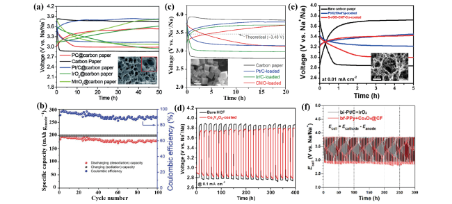
图8 (a)在0.01 mA·cm-2下,使用PC催化剂的钠基-海水半电池充放电曲线。插图为PC的SEM图[91];(b)在50 mA· g a n o d e - 1下,以PPC为催化剂的钠基-海水电池循环性能[93];(c)在0.01 mA·cm-2下,以CMO为催化剂的钠基-海水半电池充放电曲线,插图为PPC的SEM图[95];(d)在0.1 mA·cm-2下,使用Co3V2O8催化剂的钠基-海水电池循环性能[96];(e)在0.01 mA·cm-2下,使用S-rGO-CNT-Co催化剂的钠基-海水电池充放电曲线,插图为S-rGO-CNT-Co的SEM图[100];(f)在20 mA·g-1下,使用PPy+Co3O4@CF催化剂的钠基-海水电池循环性能[101]

Fig. 8 (a) Charge-discharge curves of Na-based seawater half-battery with PC catalyst at 0.01 mA·cm-2. Inset is SEM image of PC[91]. (b) Cycling performance of Na-based seawater battery with PPC catalyst at 50 mA· g a n o d e - 1 [93]. (c) Charge-discharge curves of Na-based seawater half-battery with CMO catalyst at 0.01 mA·cm-2. Inset is SEM image of CMO[95]. (d) Cycling performance of Na-based seawater battery with Co3V2O8 catalyst at 0.1 mA·cm-2[96]. (e) Charge-discharge curves of Na-based seawater battery with S-rGO-CNT-Co catalyst at 0.01 mA·cm-2. Inset is SEM image of S-rGO-CNT-Co[100]. (f) Cycling performance of Na-based seawater battery with PPy+Co3O4@CF catalyst at 20 mA·g-1[101]

3.4.2 Non-precious metal based catalyst

Compared with noble metal catalysts, non-noble metal based catalysts have the advantages of low cost, good stability and abundant sources, but their catalytic activity is poor. In order to improve the intrinsic catalytic activity of non-noble metal-based catalysts, researchers have constructed nanostructured catalysts to expose more active sites. Abirami et al. Prepared porous cobalt manganese oxide nanocubes (CMO) with large specific surface area. As shown in Figure 8 C, the half cell with CMO as the catalyst showed a low overpotential (0.53 V)[95]. By comparing the XRD and X-ray photoelectron spectroscopy (XPS) of the catalyst before and after cycling, it was found that the phase and surface electronic state of the catalyst did not change after cycling, indicating that the CMO catalyst had excellent structural stability. Shine et al. Prepared cobalt vanadate nanoparticles (Co3V2O8) by solution method and used them as sodium-based – seawater battery catalyst[96]. The porous structure of Co3V2O8 can provide more active sites and enhance the ORR/OER reaction kinetics, allowing the battery to exhibit high power density (5.9 mW·cm-2)[97]. Due to the excellent structural stability of catalyst Co3V2O8 in seawater, the full cell can be stably cycled for 20 cycles (400 H) at 0.1 mA·cm-2 (Figure 8D).

3.4.3 Composite catalyst

The ORR performance of carbon material catalysts is comparable to that of platinum-based catalysts due to their excellent conductivity and chemical stability[98,99]. However, carbon materials have low catalytic activity and are easily oxidized or corroded, resulting in the decline of battery cycle performance. On the other hand, transition metal oxides (spinel and perovskite) exhibit excellent catalytic activity for OER and ORR, but their conductivity is low. Based on the advantages and disadvantages of the above two catalysts, in order to obtain a catalyst with high activity and high conductivity, a composite catalyst is made of a transition metal material and a carbon material. Suh et al. Grew cobalt nanoparticle-doped carbon nanotubes (S-rGO-CNT-Co) on reduced graphene oxide by vapor activation combined with microwave treatment and served as a catalyst for sodium-based seawater batteries[100]. As shown in Figure 8E, the cell exhibits a small overpotential (0.4 V), excellent cycling stability, and rate capability. This is attributed to the high catalytic activity, abundant active sites, high conductivity and chemical stability of the composite catalyst. In addition, conventional air cathodes require a polymer binder to ensure good physical contact between the catalyst and the electrode. However, the electrically insulating and hydrophobic properties of the polymer binder reduce the electrochemically active surface area of the catalyst. Binderless air electrode can maximize the activity of the catalyst and improve the energy efficiency of the battery. Therefore, Kim et al. Anchored tricobalt tetroxide (Co3O4) on a carbon substrate (PPy+Co3O4@CF) by a polypyrrole-doped carbon (PPy/C) infiltration technique and used it as a sodium-based – seawater battery catalyst[101]. As shown in Fig. 8f, the PPy+Co3O4@CF exhibits excellent bifunctional catalytic activity and the cell cycling performance is comparable to that of the commercial Pt/C+IrO2 air cathode.
Due to the low solubility and slow diffusion of oxygen in seawater, ORR and OER involve complex four-electron transfer processes, resulting in slow reaction kinetics and large cell overpotential. Therefore, in order to improve the energy efficiency of the cell and reduce the overpotential, the catalyst with large specific surface area, high efficiency and high activity should be designed to reduce the ORR and OER reaction energy barrier and improve the energy efficiency and service life of the cell. The above three types of catalysts have the advantages of low cost, high activity and wide source of raw materials (biomass materials), and have considerable development prospects in sodium-based seawater batteries.

4 Conclusion and outlook

As a new type of battery, sodium-based seawater battery has attracted much attention because of its advantages of low cost, environmental protection, pollution-free and high energy density. In this paper, the electrochemical principle, cell structure design and optimization strategy of sodium-seawater battery are summarized, and the related research on the key components of sodium-seawater battery is introduced, including anode part, organic electrolyte, solid electrolyte and cathode catalyst. At present, the related theoretical research and technology are still in the initial stage, and there are still many problems to be solved before commercialization.
(1) Anode part: In order to improve the service life of anode materials and inhibit the growth of sodium dendrite, the formation mechanism, structure, composition and stability or failure mechanism of SEI layer should be further explored to form a stable SEI layer on the anode surface. In addition, the contact of sodium metal with seawater is easy to cause potential safety hazards, so it is necessary to ensure the safety of batteries in use. High-capacity anode materials (HC and P/C) improve the capacity, energy density, and safety of batteries, but suffer from poor cycling stability. Therefore, in the future, it is still necessary to strengthen the research on the preparation and modification of anode materials to help the commercialization of sodium-based seawater batteries.
(2) Organic electrolyte: Most electrolytes of sodium-ion batteries can be used in sodium-based seawater batteries, but there are still problems such as potential safety hazards and poor stability. In order to promote the development of sodium-based seawater battery, the electrolyte with low cost, high ionic conductivity and high stability should be designed by adjusting the type of solvent, sodium salt and the proportion of the two, combined with the use of functional additives (to improve conductivity, overcharge safety and stability, etc.). At the same time, Raman spectroscopy and infrared spectroscopy were used to analyze the structure and properties of the electrolyte, establish the relationship between the organic electrolyte and the performance of the battery, and summarize the mechanism and law of performance improvement.
(3) Solid electrolyte: The sodium-based seawater battery using NASICON electrolyte exhibits excellent cycle stability at low current density, but at high current density, the low ionic conductivity of NASICON electrolyte leads to low battery power density. The ionic conductivity of NASICON electrolyte at room temperature can be improved by reducing the thickness, adjusting the grain size or doping heteroatoms. In addition, from the analysis of future device application prospects, the preparation process should be optimized to obtain low-cost and high-density NASICON electrolyte.
(4) Cathode part: The cathode part plays a key role in the power density, energy efficiency, and cycling stability of sodium-based – seawater batteries. When the battery is operated at a large current density, the slow OER kinetics leads to the occurrence of side reactions (generation of hypochlorite), which reduces the energy efficiency of the battery. When the cell runs for a period of time, the overpotential increases, which may be due to the instability of the anode part or the decrease of the activity of the cathode catalyst, and the reason has not been identified. Therefore, it is necessary for researchers to use in situ/ex situ techniques (in situ XRD, Raman, etc.) To understand the internal structure of the catalyst and the nature of the catalytic process, so as to explore the reasons for the increase of overpotential. In addition, other ions and microorganisms in seawater cause damage to the battery system, resulting in battery performance degradation. For example, during the discharge process, Ca2+ and Mg2+ form insoluble precipitates at the cathode, blocking the active sites, or microorganisms and algae naturally accumulate or grow at the cathode.
To sum up, there are still many problems to be solved before the commercialization of sodium-based seawater batteries, but because of the cheap sodium source materials and the "open cathode structure", the flowing seawater can take away the heat generated by the operation of the batteries.The battery has significant advantages in terms of cost-effectiveness, thermal management, and energy density, and has the potential to be used in large-scale energy storage systems that are heated out of control due to abnormal conditions.
[1]
Ellabban O, Abu-Rub H, Blaabjerg F. Renew. Sustain. Energy Rev., 2014, 39: 748.

[2]
Hunt C T. Chem. Eng. News Archive, 2008, 86(42): 66.

[3]
Zhang Y J, Senthilkumar S T, Park J, Park J, Kim Y. Batter. Supercaps, 2018, 1(1): 6.

[4]
Vaalma C, Buchholz D, Weil M, Passerini S. Nat. Rev. Mater., 2018, 3(4): 18013.

[5]
Choi J W, Aurbach D. Nat. Rev. Mater., 2016, 1(4): 16013.

[6]
Huppes G, Ishikawa M, Kramer G J. J. Ind. Ecol., 2011, 15(5): 677.

[7]
Huang Y M, Dong Y H, Li S, Lee J, Wang C, Zhu Z, Xue W J, Li Y, Li J. Adv. Energy Mater., 2021, 11(2): 2000997.

[8]
Huang C F, Ji Q Q, Zhang H L, Wang Y T, Wang S M, Liu X H, Guo Y M, Zhang C H. J. Colloid Interface Sci., 2022, 606: 654.

[9]
Weber A. Fuel Cells, 2021, 21(5): 440.

[10]
Chang S L, Hou M J, Xu B W, Liang F, Qiu X C, Yao Y C, Qu T, Ma W H, Yang B, Dai Y N, Chen K F, Xue D F, Zhao H P, Lin X T, Poon F, Lei Y, Sun X L. Adv. Funct. Mater., 2021, 31(22): 2011151.

[11]
Wu Y Q, Qiu X C, Liang F, Zhang Q K, Koo A, Dai Y N, Lei Y, Sun X L. Appl. Catal. B Environ., 2019, 241: 407.

[12]
Kim J K, Mueller F, Kim H, Jeong S, Park J S, Passerini S, Kim Y. ChemSusChem, 2016, 9(1): 1.

[13]
Hwang S M, Park J S, Kim Y, Go W, Han J, Kim Y, Kim Y. Adv. Mater., 2019, 31(20): 1804936.

[14]
Dionigi F, Reier T, Pawolek Z, Gliech M, Strasser P. ChemSusChem, 2016, 9(9): 962.

[15]
Peled E, Golodnitsky D, Mazor H, Goor M, Avshalomov S. J. Power Sources, 2011, 196(16): 6835.

[16]
Yu J, Li B Q, Zhao C X, Zhang Q. Energy Environ. Sci., 2020, 13(10): 3253.

[17]
Son M, Park S, Kim N, Angeles A T, Kim Y, Cho K H. Adv. Sci., 2021, 8(18): 2101289.

[18]
Meng F L, Zhong H X, Bao D, Yan J M, Zhang X B. J. Am. Chem. Soc., 2016, 138(32): 10226.

[19]
Stamenkovic V, M Markovic N, Ross P N Jr. J. Electroanal. Chem., 2001, 500(1/2): 44.

[20]
Arruda T M, Shyam B, Ziegelbauer J M, Mukerjee S, Ramaker D E. J. Phys. Chem. C, 2008, 112(46): 18087.

[21]
Zhang L, Mukerjee S. J. Electrochem. Soc., 2006, 153(6): A1062.

[22]
Lane R F, Hubbard A T. J. Phys. Chem., 1975, 79(8): 808.

[23]
Wright J, Colling A. 1995, 29.

[24]
Deng J, Bae C, Marcicki J, Masias A, Miller T. Nat. Energy, 2018, 3(4): 261.

[25]
Suntivich J, Gasteiger H A, Yabuuchi N, Nakanishi H, Goodenough J B, Shao-Horn Y. Nat. Chem., 2011, 3(7): 546.

[26]
Bruce P G, Freunberger S A, Hardwick L J, Tarascon J M. Nat. Mater., 2012, 11(1): 19.

[27]
Lu X F, Xia B Y, Zang S Q, David Lou X W. Angew. Chem. Int. Ed., 2020, 59(12): 4634.

[28]
Deng Y J, Luo J M, Chi B, Tang H B, Li J, Qiao X C, Shen Y J, Yang Y J, Jia C M, Rao P, Liao S J, Tian X L. Adv. Energy Mater., 2021, 11(37): 2101222.

[29]
Schmidt T J, Paulus U A, Gasteiger H A, Behm R J. J. Electroanal. Chem., 2001, 508(1/2): 41.

[30]
Wu X Y, Han X P, Ma X Y, Zhang W, Deng Y D, Zhong C, Hu W B. ACS Appl. Mater. Interfaces, 2017, 9(14): 12574.

[31]
Shen F C, Wang Y, Tang Y J, Li S L, Wang Y R, Dong L Z, Li Y F, Xu Y, Lan Y Q. ACS Energy Lett., 2017, 2(6): 1327.

[32]
McCrory C C L, Jung S, Peters J C, Jaramillo T F. J. Am. Chem. Soc., 2013, 135(45): 16977.

[33]
Kulkarni A, Siahrostami S, Patel A, Nørskov J K. Chem. Rev., 2018, 118(5): 2302.

[34]
Huang Z F, Song J J, Du Y H, Xi S B, Dou S, Nsanzimana J M V, Wang C, Xu Z J, Wang X. Nat. Energy, 2019, 4(4): 329.

[35]
Kang Y, Wang S, Zhu S Q, Gao H X, Hui K S, Yuan C Z, Yin H, Bin F, Wu X L, Mai W J, Zhu L, Hu M C, Liang F, Chen F M, Hui K N. Appl. Catal. B Environ., 2021, 285: 119786.

[36]
Xia B Y, Yan Y, Li N, Wu H B, Lou X W, Wang X. Nat. Energy, 2016, 1: 15006.

[37]
Meier J C, Galeano C, Katsounaros I, Witte J, Bongard H J, Topalov A A, Baldizzone C, Mezzavilla S, Schüth F, Mayrhofer K J J. Beilstein J. Nanotechnol., 2014, 5: 44.

[38]
Job N, Chatenet M, Berthon-Fabry S, Hermans S, Maillard F. J. Power Sources, 2013, 240: 294.

[39]
Shinde S S, Lee C H, Sami A, Kim D H, Lee S U, Lee J H. ACS Nano, 2017, 11(1): 347.

[40]
Guo L, Rueping M. Acc. Chem. Res., 2018, 51(5): 1185.

[41]
Zhang D, Zhao H P, Liang F, Ma W H, Lei Y. J. Power Sources, 2021, 493: 229722.

[42]
Lu L, Zheng Y, Yang R, Kakimov A, Li X. Mater. Today Chem., 2021, 21: 100488.

[43]
Kim Y, Kim H, Park S, Seo I, Kim Y. Electrochimica Acta, 2016, 191: 1.

[44]
Kim Y, Varzi A, Mariani A, Kim G T, Kim Y, Passerini S. Adv. Energy Mater., 2021, 11(38): 2102061.

[45]
Gao H X, Zhu S Q, Kang Y, Dinh D A, Hui K S, Bin F, Fan X, Chen F M, Mahmood A, Geng J X, Cheong W C M, Hui K N. ACS Appl. Energy Mater., 2022, 5(2): 1662.

[46]
Kim Y, Kim G T, Jeong S, Dou X W, Geng C X, Kim Y, Passerini S. Energy Storage Mater., 2019, 16: 56.

[47]
Yin W W, Fu Z W. ChemCatChem, 2017, 9(9): 1545.

[48]
Kim Y, Ha K H, Oh S M, Lee K T. Chem. Eur. J., 2014, 20(38): 11980.

[49]
Han J, Hwang S M, Go W, Senthilkumar S T, Jeon D, Kim Y. J. Power Sources, 2018, 374: 24.

[50]
Kim Y, Harzandi A M, Lee J, Choi Y, Kim Y. Adv. Sustainable Syst., 2021, 5(1): 2000106.

[51]
Kim Y, Shin K, Jung Y, Lee W G, Kim Y. Adv. Sustain. Syst., 2022, 6(6): 2100484.

[52]
Wang H, Yu D D, Kuang C W, Cheng L W, Li W, Feng X L, Zhang Z, Zhang X B, Zhang Y. Chem, 2019, 5(2): 313.

[53]
Sun J, Lee H W, Pasta M, Yuan H T, Zheng G Y, Sun Y M, Li Y Z, Cui Y. Nat. Nanotechnol., 2015, 10(11): 980.

[54]
Zhao C L, Lu Y X, Yue J M, Pan D, Qi Y R, Hu Y S, Chen L Q. J. Energy Chem., 2018, 27(6): 1584.

[55]
Hong Y S, Li N, Chen H S, Wang P, Song W L, Fang D N. Energy Storage Mater., 2018, 11: 118.

[56]
Senthilkumar S T, Go W, Han J, Pham Thi Thuy L, Kishor K, Kim Y, Kim Y. J. Mater. Chem. A, 2019, 7(40): 22803.

[57]
Kim D H, Choi H, Hwang D Y, Park J, Kim K S, Ahn S, Kim Y, Kwak S K, Yu Y J, Kang S J. J. Mater. Chem. A, 2018, 6(40): 19672.

[58]
Liang F, Qiu X C, Zhang Q K, Kang Y, Koo A, Hayashi K, Chen K F, Xue D F, Hui K N, Yadegari H, Sun X L. Nano Energy, 2018, 49: 574.

[59]
Kim Y, Jung J, Yu H, Kim G T, Jeong D, Bresser D, Kang S J, Kim Y, Passerini S. Adv. Funct. Mater., 2020, 30(24): 2001249.

[60]
Lim D H, Dong C, Kim H W, Bae G H, Choo K, Cho G B, Kim Y, Jin B, Kim J K. Mater. Today Energy, 2021, 21: 100805.

[61]
Luo W, Shen F, Bommier C, Zhu H L, Ji X L, Hu L B. Acc. Chem. Res., 2016, 49(2): 231.

[62]
Hu Z, Liu Q N, Chou S L, Dou S X. Adv. Mater., 2017, 29(48): 1700606.

[63]
Kim H, Park J S, Sahgong S H, Park S, Kim J K, Kim Y. J. Mater. Chem. A, 2014, 2(46): 19584.

[64]
Lee S, Cho I Y, Kim D, Park N K, Park J, Kim Y, Kang S J, Kim Y, Hong S Y. ChemSusChem, 2020, 13(9): 2220.

[65]
Armand M, Endres F, MacFarlane D R, Ohno H, Scrosati B. Nat. Mater., 2009, 8(8): 621.

[66]
Watanabe M, Thomas M L, Zhang S G, Ueno K, Yasuda T, Dokko K. Chem. Rev., 2017, 117(10): 7190.

[67]
Kim Y, Hwang S M, Yu H, Kim Y. J. Mater. Chem. A, 2018, 6(7): 3046.

[68]
Kim J K, Mueller F, Kim H, Bresser D, Park J S, Lim D H, Kim G T, Passerini S, Kim Y. NPG Asia Mater., 2014, 6(11): e144.

[69]
Lu Y, Li L, Zhang Q, Niu Z Q, Chen J. Joule, 2018, 2(9): 1747.

[70]
Tang B, Jaschin P W, Li X, Bo S H, Zhou Z. Mater. Today, 2020, 41: 200.

[71]
Yao Y F Y, Kummer J T. J. Inorg. Nucl. Chem., 1967, 29(9): 2453.

[72]
Whittingham, Stanley M. J. Chem. Phys., 1971, 54(1): 414.

[73]
Kim K K, Mundy J N, Chen W K. J. Phys. Chem. Solids, 1979, 40(10): 743.

[74]
La Rosa D, Monforte G, D’Urso C, Baglio V, Antonucci V, Aricò A S. ChemSusChem, 2010, 3(12): 1390.

[75]
Chi C, Katsui H, Goto T. Ceram. Int., 2017, 43(1): 1278.

[76]
Lu X C, Xia G G, Lemmon J P, Yang Z G. J. Power Sources, 2010, 195(9): 2431.

[77]
Will F G. J. Electrochem. Soc., 1976, 123(6): 834.

[78]
Flor G, Marini A, Massarotti V, Villa M. Solid State Ion., 1981, 2(3): 195.

[79]
Farrington G C, Briant J L. Mater. Res. Bull., 1978, 13(8): 763.

[80]
Harbach F. Solid State Ion., 1983, 9/10: 231.

[81]
Goodenough J B, Hong H Y P, Kafalas J A. Mater. Res. Bull., 1976, 11(2): 203.

[82]
Park H, Jung K, Nezafati M, Kim C S, Kang B. ACS Appl. Mater. Interfaces, 2016, 8(41): 27814.

[83]
Zhao C L, Liu L L, Qi X G, Lu Y X, Wu F X, Zhao J M, Yu Y, Hu Y S, Chen L Q. Adv. Energy Mater., 2018, 8(17): 1703012.

[84]
Senthilkumar S T, Han J, Park J, Hwang S M, Jeon D, Kim Y. Energy Storage Mater., 2018, 12: 324.

[85]
Hwang S M, Kim J, Kim Y, Kim Y. J. Mater. Chem. A, 2016, 4(46): 17946.

[86]
Hou M J, Yang X C, Liang F, Dong P, Chen Y N, Li J R, Chen K F, Dai Y N, Xue D F. ACS Appl. Mater. Interfaces, 2021, 13(28): 33262.

[87]
Kim K, Hwang S M, Park J S, Han J, Kim J, Kim Y. J. Power Sources, 2016, 313: 46.

[88]
Sahgong S H, Senthilkumar S T, Kim K, Hwang S M, Kim Y. Electrochem. Commun., 2015, 61: 53.

[89]
Yang X C, Su F M, Hou M J, Zhang D, Dai Y N, Liang F. Dalton Trans., 2021, 50(20): 7041.

[90]
Ping H, Tao Z, Jie J, Zhou H S. J. Phys. Chem. Lett., 2016, 7(7): 1267.

[91]
Senthilkumar S T, Park S O, Kim J, Hwang S M, Kwak S K, Kim Y. J. Mater. Chem. A, 2017, 5(27): 14174.

[92]
Li W J, Han C, Zhang K, Chou S L, Dou S X. J. Mater. Chem. A, 2021, 9(11): 6671.

[93]
Kim J, Park J, Lee J, Lim W G, Jo C, Lee J. Adv. Funct. Mater., 2021, 31(22): 2010882.

[94]
Zhang J T, Zhao Z H, Xia Z H, Dai L M. Nat. Nanotechnol., 2015, 10(5): 444.

[95]
Abirami M, Hwang S M, Yang J C, Senthilkumar S T, Kim J, Go W S, Senthilkumar B, Song H K, Kim Y. ACS Appl. Mater. Interfaces, 2016, 8(48): 32778.

[96]
Shin K H, Park J, Park S K, Nakhanivej P, Hwang S M, Kim Y, Park H S. J. Ind. Eng. Chem., 2019, 72: 250.

[97]
Liardet L, Hu X L. ACS Catal., 2018, 8(1): 644.

[98]
Pletcher D, Li X H, Price S W T, Russell A E, Sönmez T, Thompson S J. Electrochimica Acta, 2016, 188: 286.

[99]
Mahmood J, Li F, Kim C, Choi H J, Gwon O, Jung S M, Seo J M, Cho S J, Ju Y W, Jeong H Y, Kim G, Baek J B. Nano Energy, 2018, 44: 304.

[100]
Suh D H, Park S K, Nakhanivej P, Kim Y, Hwang S M, Park H S. J. Power Sources, 2017, 372: 31.

[101]
Kim C, Kim S, Kwon O, Kim J, Kim G. ChemElectroChem, 2019, 6(1): 2.

[102]
Zhang Y J, Park J S, Senthilkumar S T, Kim Y. J. Power Sources, 2018, 400: 478.

[103]
Khan Z, Park S O, Yang J C, Park S, Shanker R, Song H K, Kim Y, Kwak S K, Ko H. J. Mater. Chem. A, 2018, 6(47): 24459.

[104]
Dien Kha Tu N, Park S O, Park J, Kim Y, Kwak S K, Kang S J. ACS Appl. Energy Mater., 2020, 3(2): 1602.

[105]
Kim S, Ji S, Yang H, Son H, Choi H, Kang J, Li O L. Appl. Catal. B Environ., 2022, 310: 121361.

Outlines

/