
Mechanistic Insights into Electrocatalytic Urea Oxidation Reaction Through in situ Characterizations
Received date: 2025-08-05
Revised date: 2025-09-10
Online published: 2025-09-18
Supported by
Henan Province Science and Technology Research Project(242102230037)
Henan Province Science and Technology Research Project(252102231024)
Henan Province Science and Technology Research and Development Plan Joint Fund(Industry Category)(202324111)
The electrocatalytic urea oxidation reaction (UOR) has emerged as an energy-efficient alternative to the traditional oxygen evolution reaction for hydrogen production, with mechanistic understanding being critical for the rational design of catalysts. This review systematically summarizes recent advances in in situ characterization techniques for elucidating the dynamic reaction mechanisms of UOR. Studies reveal that phase transitions, valence state migration, and electronic structure evolution of catalysts under operational conditions are key factors governing activity and stability. Techniques such as in situ X-ray diffraction, X-ray absorption spectroscopy, Raman spectroscopy, and Fourier-transform infrared spectroscopy enable real-time monitoring of catalyst reconstruction, intermediate evolution, and interfacial adsorption behavior, overcoming the environmental deviations inherent in conventional ex situ characterization. When combined with theoretical calculations, these methods provide direct evidence for identifying active-site configurations, reaction pathways, and rate-determining steps. In addition, special emphasis is placed on multimodal in situ strategies for deciphering synergistic effects in nickel-based catalysts, while current challenges, including non-alkaline systems, real wastewater environments, and multi-metal cooperation mechanisms, are critically discussed. Future research should focus on developing novel in situ approaches for complex systems and establishing a mutually reinforcing framework integrating theoretical prediction and experimental validation, thereby advancing UOR catalyst design from empirical exploration to mechanism-guided optimization.
1 Introduction
2 Overview of the electrocatalytic UOR
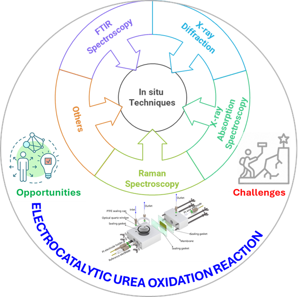
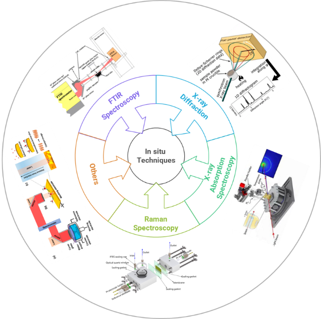
3 Overview of in situ characterizations
4 In situ monitoring the dynamic evolution of catalysts during UOR
5 In situ characterizations to reveal the UOR mechanism
6 Conclusions and perspectives
Suzhen Bai , Yi Zeng , Zhengshan Tian , Kesheng Cao , Xingwu Li , Haoqi Wang . Mechanistic Insights into Electrocatalytic Urea Oxidation Reaction Through in situ Characterizations[J]. Progress in Chemistry, 2025 , 37(12) : 1769 -1791 . DOI: 10.7536/PC20250801
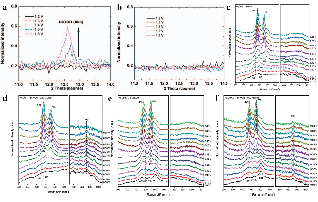
图3 (a) Ni(OH)2电极在5 M KOH中从1.2~1.6 V电位范围内的NiOOH (003)晶面原位XRD图谱。(b) 含1 M尿素的5 M KOH电解液中Ni(OH)2电极从1.2~1.6 V电位范围内的NiOOH (003)晶面原位XRD图谱。(c) 1 M KOH和(d) 1 M KOH + 0.33 M尿素电解液中Ni(OH)2电极在不同电位下的原位拉曼光谱。(e) 1 M KOH和(f) 1 M KOH + 0.33 M尿素电解液中Ni0.2Mn0.8电极在不同电位下的原位拉曼光谱Fig.3 (a) In situ XRD of NiOOH (003) from 1.2 to 1.6 V for Ni(OH)2 in 5 M KOH. (b) In situ XRD of NiOOH (003) from 1.2 to 1.6 V for Ni(OH)2 electrode in 5 M KOH with 1 M urea[68]. Copyright 2014, The Author(s). In situ Raman spectra for Ni(OH)2 at various potentials in (c) 1 M KOH and (d) 1 M KOH + 0.33 M urea. In situ Raman spectra for Ni0.2Mn0.8 at various potentials vs. Hg/HgO in (e) 1 M KOH and (f) 1 M KOH + 0.33 M urea[69]. Royal Society of Chemistry 2022 |
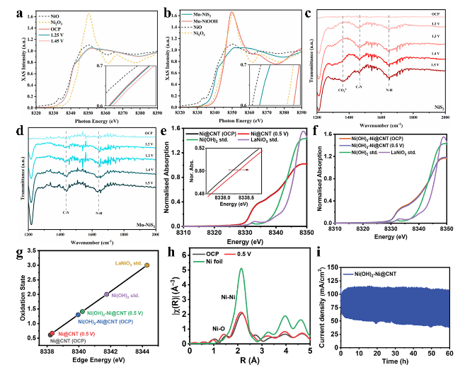
图4 (a) Mn-NiS2材料从OCP至1.45 V电位范围内的镍K边原位XANES光谱。(b) Mn-NiS2、Mn-NiOOH及参比材料的镍K边XANES光谱。(c) NiS2和(d) Mn-NiS2在UOR过程的计时电位法原位ATR-SEIRAS光谱。(e) Ni@CNT和(f) Ni(OH)2-Ni@CNT在开路电位及UOR电位(1 M KOH + 0.4 M尿素电解液)下的原位镍K边XANES光谱。(g) Ni@CNT和Ni(OH)2-Ni@CNT催化剂在不同电位下的边前能量与镍氧化态变化。(h) Ni(OH)2-Ni@CNT在OCP及0.5 V电位下的原位傅里叶变换扩展X射线吸收精细结构谱。(i) 活性催化剂Ni(OH)2在0.75 V电位下的计时电流曲线Fig.4 (a) In situ XANES spectra of the Ni K-edge of Mn-NiS2 and reference materials recorded from OCP to 1.45 V vs RHE. (b) XANES spectra of the Ni K-edge of Mn-NiS2, Mn-NiOOH, and reference materials. In situ ATR-SEIRAS was obtained during chronopotentiometry in a potential window from OCP to 1.5 V vs. RHE for (c) NiS2 and (d) Mn-NiS2 toward UOR[70]. Copyright 2024 American Chemical Society. In-situ Ni-K edge XANES of (e) Ni@CNT and (f) Ni(OH)2-Ni@CNT at OCP and UOR potential (1 M KOH + 0.4 M urea), compared with ex-situ standards (Ni(OH)2 and LaNiO3). (g) Edge energy and oxidation states of Ni@CNT and Ni(OH)2-Ni@CNT catalysts at various potentials. (h) In-situ FT-EXAFS of Ni(OH)2-Ni@CNT at OCP and urea electrooxidation reaction at 0.5 V in 1 M KOH + 0.4 M urea. (i) Chronoamperometry of the active catalyst Ni(OH)2 at 0.75 V vs. Hg/HgO[72]. Copyright 2025, Elsevier |
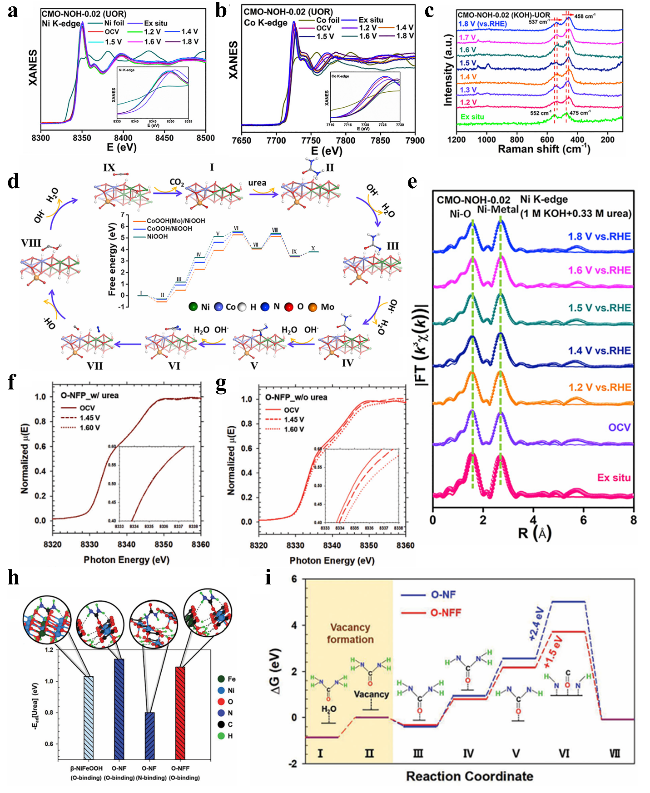
图5 原位电化学研究:(a) CMO-NOH-0.02在1.2~1.8 V电位范围内的镍K边和(b)钴K边原位XANES光谱;(c) CMO-NOH-0.02在1.2~1.8 V电位范围内的原位电化学拉曼光谱;(d) CoOOH(Mo)/NiOOH表面尿素氧化反应机理示意图;(e) 基于(a)中数据得到的CMO-NOH-0.02镍K边光谱傅里叶变换图。O-NFP在0.5 M KOH电解液中(f)含尿素和(g)不含尿素条件下的操作XANES分析;(h) 尿素吸附能;(i) O-NF和O-NFF催化剂上尿素氧化反应的自由能变化图Fig. 5 In situ electrochemistry (a) Ni K-edge and (b) Co K-edge XANES spectra of CMO-NOH-0.02 at the potentials of 1.2~1.8 V vs. RHE, (c) In situ ERS of CMO-NOH-0.02 (KOH) at the potentials of 1.2~1.8 V vs. RHE, (d) Proposed reaction mechanism for urea oxidation on CoOOH(Mo)/NiOOH surface, (e) Fourier transforms of Ni K-edge spectra for the CMO-NOH-0.02 obtained from (a)[74]. Copyright 2023, The Author(s). Operando XANES analysis of O-NFP in 0.5 M KOH (f) with and (g) without urea. (h) Urea adsorption energy. (i) ΔG diagram of UOR on O-NF and O-NFF[75]. Copyright 1999-2025 Wiley |
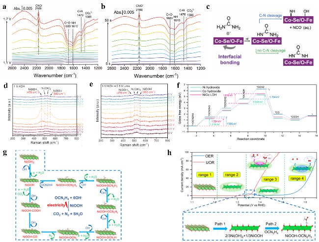
图6 (a) Fe-Co₀.₈₅Se/FeCo LDH在恒定电位下的原位傅里叶变换红外光谱。(b) Fe-Co₀.₈₅Se/FeCo LDH在1.45 V恒定电位下的原位时间分辨FTIR测量。(c) 尿素氧化反应关键步骤中可能中间体的示意图。不同电解液中Ni₀.₈₆₄Co₀.₁₃₆ LDH的原位拉曼研究:(d) 1 M KOH和(e) 含0.5 M尿素的1 M KOH电解液;(f) 氢氧化镍表面UOR的自由能变曲线;(g) UOR过程示意图;(h) Ni₀.₈₆₄Co₀.₁₃₆ LDH在不同电压区间催化过程的示意图Fig.6 (a) In situ FTIR spectra for Fe-Co0.85Se/FeCo LDH at constant potentials. (b) In situ time-resolved FTIR measurements of Fe-Co0.85Se/FeCo LDH at a constant potential of 1.45 V vs. RHE. (c) A schematic illustration of the possible intermediates in the key steps for UOR[78]. Copyright 1999-2025 Wiley. In situ Raman investigations on Ni0.864Co0.136 LDH with different electrolytes: (d) 1 M KOH and (e) 1 M KOH with 0.5 M urea, (f) reaction coordinates free energy profiles of UOR on Ni hydroxide, (g) schematic diagram of UOR process; (h) schematic diagram of catalytic process of Ni0.864Co0.136 LDH at different voltage ranges[79]. Copyright 2025 Elsevier |
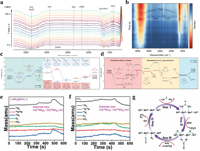
图7 (a) LNO-2在1.45 V施加电位下的全范围原位ATR-FTIR光谱。(b) LNO-2在1.35 V施加电位下的放大区域原位FTIR光谱。(c) LNO-0的AEM与LOM机制反应路径图。(d) LNO-0和LNO-2在(003)晶面上沿LOM机制路径的自由能变化曲线。(e) l-NiS2@MnOx在含0.33 M尿素(CO(¹⁴NH₂)₂∶ CO(¹⁵NH₂)₂ = 4∶1)的1 M KOH中催化的原位电化学质谱同位素示踪实验结果。(f) NiS2在含0.33 M尿素[CO(¹⁴NH₂)₂∶ CO(¹⁵NH₂)₂ = 4∶1]的1 M KOH中的原位电化学质谱同位素示踪实验。(g) 尿素在NiS2@MnOx阳极上的转化示意图Fig. 7 (a) Full range in situ ATR-FTIR spectra of the LNO-2 at applied potentials of 1.45 V. (d) Magnified in situ FTIR spectra of the LNO-2 catalysts at applied potentials of 1.35 V. (c) Pathway of AEM and LOM mechanism for LNO-0. d) Free energy profiles along pathways of the LOM mechanism on the (003) of LNO-0 and LNO-2[81]. Copyright 2022 Wiley. (e) In situ electrochemistry mass spectrometry isotope tracing experiment under the catalysis of l-NiS2@MnOx in 1 M KOH with 0.33 M urea (CO(14NH2)2∶CO(15NH2)2 = 4∶1). (f) In situ electrochemistry mass spectrometry isotope tracing experiment under the catalysis of NiS2 in 1 M KOH with 0.33 M urea. (g) The conversion process of urea over a NiS2@MnOx anode[82]. Royal Society of Chemistry 2022 |
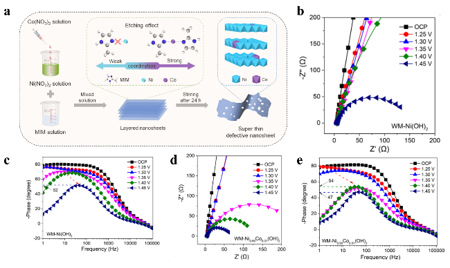
图8 (a) 通过痕量钴掺杂诱导缺陷工程制备缺陷型WM-Ni0.99Co0.01(OH)2的合成示意图。操作电化学阻抗谱测量:(b, c) 分别在WM-Ni(OH)2和WM-Ni0.99Co0.01(OH)2不同阳极极化电位下采集的奈奎斯特图;(d, e)分别在WM-Ni(OH)2和WM-Ni0.99Co0.01(OH)2不同阳极极化电位下采集的伯德相位图Fig. 8 (a) Synthesis of defective WM-Ni0.99Co0.01(OH)2 by trace Co doping-induced defect engineering. Operando EIS measurements: (b, c) Nyquist plots collected under different anodic polarization potentials for WM-Ni(OH)2 and WM-Ni0.99Co0.01(OH)2, respectively; (d, e) Bode-phase plots collected under different anodic polarization potentials for WM-Ni(OH)2 and WM-Ni0.99Co0.01(OH)2, respectively[83]. Copyright 2023, The Author(s) |
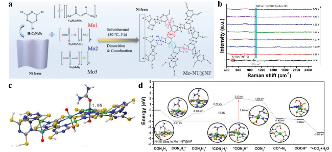
图9 (a) Mo-NT@NF材料制备过程示意图;(b) Mo₁-NT@NF在1 M KOH及1 M KOH + 0.33 M尿素电解液中随电位变化的原位拉曼光谱;(c) Mo-NT@NF催化剂中Ni³⁺与尿素分子相互作用的计算结合能;(d) UOR在Mo-NT@NF镍活性位点上的能量路径图Fig.9 (a) Schematic illustration of the fabrication of Mo-NT@NF, (b) Potential-dependent in situ Raman spectra of Mo1-NT@NF in 1 M KOH 1 M KOH + 0.33 M urea. (c) Calculated interaction energy between Ni³⁺ in the Mo-NT@NF catalyst and a urea molecule. (d) The energy pathways of UOR on the Ni sites of Mo-NT@NF[84]. Copyright 2023 Wiley |
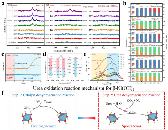
图10 (a) β-Ni(OH)2电极在含0、50和500 mM尿素的1 M KOH电解液中进行OER/UOR过程中的原位拉曼光谱;(b) β-Ni(OH)2电极在含0、50和500 mM尿素的1 M KOH电解液中的准原位XPS光谱;(c) 使用CO(¹⁴NH₂)₂进行尿素氧化反应周期性测量的原位微分电化学质谱;(d) β-Ni(OH)2电极在2800~3500 cm⁻¹波数范围内进行尿素氧化反应的同步辐射FTIR光谱;(e) β-Ni(OH)2电极在含0.5 M尿素的操作电化学阻抗谱测量;(f) β-Ni(OH)2电极上的UOR机理示意图Fig. 10 (a) In situ Raman spectra of the β-Ni(OH)2 electrode in 1 M KOH with urea during OER/UOR, (b) quasi in situ XPS spectra for the β-Ni(OH)2 electrode in 1 M KOH with 0, 50, and 500 mM urea, (c) In situ DEMS for periodic measurement of the UOR with CO(14NH2)2. (d) Operando SR-FTIR spectroscopy for the UOR over β-Ni(OH)2 electrode in the range of 2800 to 3500 cm-1. (e) Operando EIS measurements of β-Ni(OH)₂ electrode in 1 M KOH containing 0.5 M urea, (f) The UOR mechanism on the β-Ni(OH)2 electrode[85]. Copyright 2021 Wiley |
| [1] |
|
| [2] |
|
| [3] |
|
| [4] |
|
| [5] |
|
| [6] |
|
| [7] |
|
| [8] |
(薛世翔, 吴攀, 赵亮, 南艳丽, 雷琬莹. 化学进展, 2022, 34(12): 2686)
|
| [9] |
|
| [10] |
|
| [11] |
|
| [12] |
|
| [13] |
|
| [14] |
|
| [15] |
|
| [16] |
|
| [17] |
|
| [18] |
|
| [19] |
|
| [20] |
|
| [21] |
|
| [22] |
|
| [23] |
|
| [24] |
|
| [25] |
|
| [26] |
|
| [27] |
|
| [28] |
|
| [29] |
|
| [30] |
|
| [31] |
|
| [32] |
|
| [33] |
|
| [34] |
|
| [35] |
|
| [36] |
|
| [37] |
|
| [38] |
|
| [39] |
|
| [40] |
|
| [41] |
|
| [42] |
|
| [43] |
|
| [44] |
|
| [45] |
|
| [46] |
|
| [47] |
|
| [48] |
|
| [49] |
|
| [50] |
|
| [51] |
|
| [52] |
|
| [53] |
|
| [54] |
|
| [55] |
|
| [56] |
|
| [57] |
|
| [58] |
|
| [59] |
(丰收, 湛佳宇, 张鲁华. 化学进展, 2022, 34(4): 983)
|
| [60] |
|
| [61] |
|
| [62] |
|
| [63] |
|
| [64] |
|
| [65] |
|
| [66] |
|
| [67] |
|
| [68] |
|
| [69] |
|
| [70] |
|
| [71] |
(陈信, 王镜朝, 崔翔明, 周密, 王嘉楠, 延卫. 化学进展, 2025, 37(5): 758)
|
| [72] |
|
| [73] |
|
| [74] |
|
| [75] |
|
| [76] |
(卢明龙, 张晓云, 杨帆, 王练, 王育乔. 化学进展, 2022, 34(3): 547)
|
| [77] |
|
| [78] |
|
| [79] |
|
| [80] |
|
| [81] |
|
| [82] |
|
| [83] |
|
| [84] |
|
| [85] |
|
/
| 〈 |
|
〉 |