
†These authors contributed equally to this work.
Received date: 2025-04-06
Revised date: 2025-07-13
Online published: 2025-10-25
Supported by
Heilongjiang Province Key R&D Program(2023ZX04A01)
National Key Research and Development Program(2021YFC2902905)
Chongqing Key Technology Innovation and Application Development Project(2022TIAD-DEX0024)
Chongqing Key Technology Innovation and Application Development Project(2023TIAD-KPX0007)
Beijing Nova Program,and the Natural Science Foundation of Chongqing, China(2022NSCQ-JQX3895)
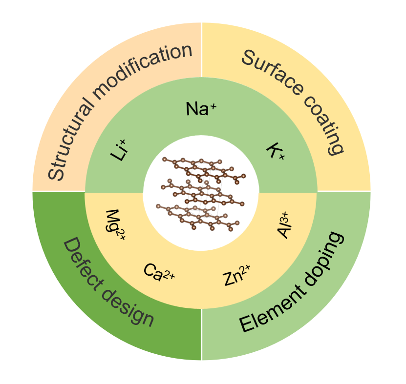
With the increasing proportion of renewable energy in the energy structure, the development of efficient and safe secondary battery energy storage technologies is crucial for addressing the challenges of integrating intermittent energy sources such as wind and solar power into the grid. Due to its unique structure and physicochemical properties, graphite anode material has been widely used in lithium-ion batteries. Inspired by the lithium storage behavior of graphite, its application in other metal-ion batteries has also been extensively studied, demonstrating significant potential. However, the application of graphite anode materials in various metal-ion secondary batteries still lacks a comprehensive understanding. This review analyzes the electrochemical behavior of graphite in different metal-ion secondary battery systems, identifies the challenges faced by graphite materials, and highlights the primary strategies and current research progress in addressing these issues. The aim is to provide a reference for the development of high-performance and sustainable graphite-based energy storage batteries.
1 Introduction
2 Basic concepts of graphite materials
2.1 Crystal structure of graphite
2.2 Graphite intercalation compound
2.3 Types of Graphite Anodes for Batteries
3 Lithium-ion batteries
3.1 Challenges faced by graphite anode of lithium ion battery
3.2 Modification methods and research progress
4 Sodium ion battery
4.1 Present situation and challenge of graphite anode in sodium ion battery
4.2 Modification strategy of graphite anode
5 Potassium ion battery
5.1 Potassium storage mechanism of graphite anode
5.2 Challenge of graphite anode in potassium ion battery
5.3 Modification method
6 Multivalent metal ion battery
6.1 magnesium ion battery
6.2 Calcium ion battery
6.3 Zinc ion battery
6.4 Aluminum ion battery
7 Summary and prospect
Qingdong Wang , Zitao Wang , Yu Dong , Tao Liu , Ning Li , Yuefeng Su . Graphite Materials in Metal-Ion Secondary Batteries[J]. Progress in Chemistry, 2025 , 37(12) : 1820 -1835 . DOI: 10.7536/PC20250408
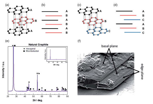
图1 (a) 六方石墨结构示意图;(b) 六方石墨基面和边缘面示意图;(c) 三方石墨结构示意图; (d) 三方石墨基面和边缘面示意图[14];(e) 天然石墨的XRD谱图;(f) 石墨的SEM图[15]Fig.1 (a) Illustration of hexagonal graphite structure; (b) illustration of the basal and edge plane surfaces of hexagonal graphite; (c) illustration of rhombohedral graphite structure; (d) illustration of the basal and edge plane surfaces of rhombohedral graphite; Reproduced with permission[14]. Copyright 2023, Royal Society of Chemistry. (e) XRD patterns of natural graphite; (f) SEM image of graphite. Reproduced with permission[15]. Copyright 2020, Royal Society of Chemistry |
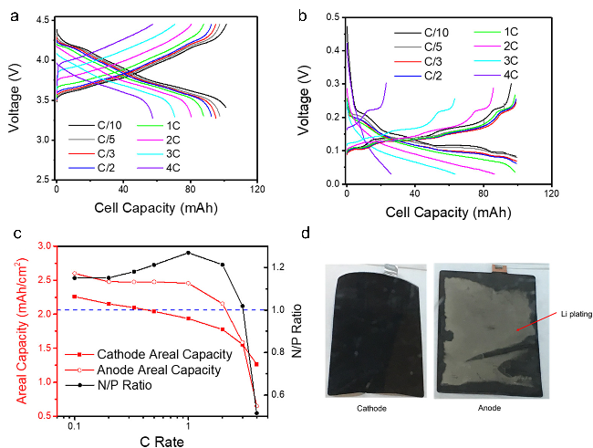
图2 (a) 对称电池中NMC811正极的电压分布, 电极在C/5下锂化,以不同的速率去锂化;(b) 对称电池中石墨负极的电压分布, 电极在C/5时脱锂, 并以不同的速率锂化;(c) NMC 811正极和石墨负极在不同速率下的面积容量以及由此产生的N/P比;(d) 来自NMC 811||石墨全电池的电极在充电速率性能测试后的图像[26]Fig.2 (a) Voltage profiles of NMC811 in the cathode symmetric cell. The electrode was lithiated at C/5 and delithiated at various rates. (b) Voltage profiles of graphite in the anode symmetric cell. The electrode was delithiated at C/5 and lithiated at various rates. (c) Areal capacity of the NMC811 cathode and graphite anode at each rate and the resulting N/P ratio. (d) Images of electrodes from the NMC811/Graphite full cell after charging rate performance test. Reproduced with permission[26]. Copyright 2018, Elsevier |
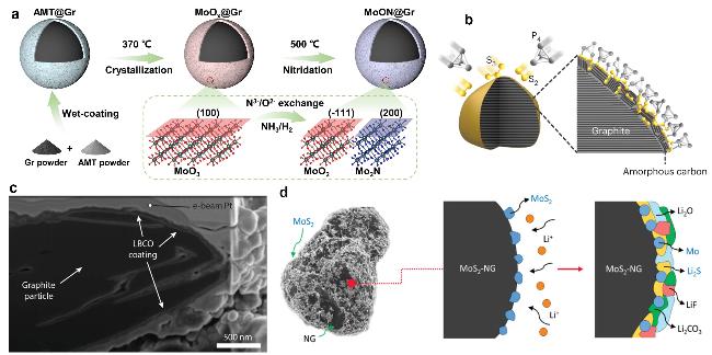
图4 (a) MoON@Gr合成示意图[35];(b) P-S-石墨形成机制示意图[36];(c) 聚焦离子束穿过单个LBCO包覆石墨颗粒的横剖面的SEM图像[37];(d) MoS2包覆石墨的SEI形成示意图[38]Fig. 4 (a) Synthetic schematic diagram of MoON@Gr. Reproduced with permission[35]. Copyright 2024, Wiley; (b) schematic of the formation mechanism of P-S-graphite. Reproduced with permission[36]. Copyright 2023, Springer Nature. (c) SEM image of focused-ion beam cross-section through a single graphite particle showing the conformal LBCO encapsulation of the particle. Reproduced with permission[37]. Copyright 2022, Wiley. (d) Schematic description of the SEI composition and reaction coordinates for MoS2-NG.; Reproduced with permission[38].Copyright 2025, Wiley |
表1 使用不同改性方法的石墨负极性能表现Table 1 Performance of graphite anode with different modification methods |
| Methods | Materials | Cycle performance (rate, cycle times, capacity retention rate) | Rate performance (rate, specific capacity) |
|---|---|---|---|
| Surface engineering | MoON@Gr[35] | 6 C, 4000, 85% | 5 C, 300 mAh/g |
| P-S-graphite[36] | 8 C, 2500, 81.7% | 10 C,130 mAh/g | |
| Al2O3@graphite[50] | 0.4 A/g, 100, 83% | 4 A/g, 337 mAh/g | |
| SGT@FC-N[51] | 1 C, 900, 93% | 15 C, 170 mAh/g | |
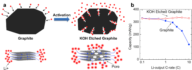
| Structure design | KOH-etched graphite[52] | 6 C, 100,74% | 6 C, 74 mAh/g |
| Expanded graphite[53] | 1 A/g, 700, 100% | 5 A/g, 208 mAh/g | |
| Nitrogen-doped hollow graphite[54] | 1 A/g, 500, 100% | 3 A/g, 200 mAh/g | |
| porous graphite nanosheet[44] | 4 C, 500, 90% | 8 C, 325 mAh/g | |
| Electrolyte engineering | 1.8 M LiFSI in DOL[55] | 20 C, 4000, 80% | 50 C, 180 mAh/g |
| 1 M LiTFSI in FEC/CPME[46] | 1 C, 300, 85% | 5 C, 150 mAh/g | |
| 0.02 M LiPF6 in EC/DMC[56] | 0.5 C, 200, 77.4% | 2 C, 140 mAh/g | |
| LHCE[57] | 4 C, 200, 85.5% | 4 C, 220 mAh/g |
| [1] |
|
| [2] |
|
| [3] |
|
| [4] |
|
| [5] |
|
| [6] |
|
| [7] |
|
| [8] |
|
| [9] |
|
| [10] |
|
| [11] |
|
| [12] |
|
| [13] |
|
| [14] |
|
| [15] |
|
| [16] |
|
| [17] |
|
| [18] |
|
| [19] |
|
| [20] |
|
| [21] |
|
| [22] |
|
| [23] |
|
| [24] |
|
| [25] |
|
| [26] |
|
| [27] |
|
| [28] |
|
| [29] |
|
| [30] |
|
| [31] |
|
| [32] |
|
| [33] |
|
| [34] |
|
| [35] |
|
| [36] |
|
| [37] |
|
| [38] |
|
| [39] |
|
| [40] |
|
| [41] |
|
| [42] |
|
| [43] |
|
| [44] |
|
| [45] |
|
| [46] |
|
| [47] |
|
| [48] |
|
| [49] |
|
| [50] |
|
| [51] |
|
| [52] |
|
| [53] |
|
| [54] |
|
| [55] |
|
| [56] |
|
| [57] |
|
| [58] |
|
| [59] |
|
| [60] |
|
| [61] |
|
| [62] |
|
| [63] |
|
| [64] |
|
| [65] |
|
| [66] |
|
| [67] |
|
| [68] |
|
| [69] |
|
| [70] |
|
| [71] |
|
| [72] |
|
| [73] |
|
| [74] |
|
| [75] |
|
| [76] |
|
| [77] |
|
| [78] |
|
| [79] |
|
| [80] |
|
| [81] |
|
| [82] |
|
| [83] |
|
| [84] |
|
| [85] |
|
| [86] |
|
| [87] |
|
| [88] |
|
| [89] |
|
| [90] |
|
| [91] |
|
| [92] |
|
| [93] |
|
| [94] |
|
| [95] |
|
| [96] |
|
| [97] |
|
| [98] |
|
| [99] |
|
| [100] |
|
| [101] |
|
| [102] |
|
| [103] |
|
| [104] |
|
| [105] |
|
| [106] |
|
| [107] |
|
| [108] |
|
/
| 〈 |
|
〉 |