Home Journals Progress in Chemistry
Progress in Chemistry

Abbreviation (ISO4): Prog Chem      Editor in chief: Jincai ZHAO

About  /  Aim & scope  /  Editorial board  /  Indexed  /  Contact  / 
Review

Applications and Challenges of Advanced Characterization Techniques in All-Solid-State Lithium-Sulfur Battery Cathodes

  • Jiawei Li ,
  • Guobao Xu , *
Expand
  • Hunan Provincial Key Laboratory of Thin Film Materials and Devices, School of Materials Science and Engineering, Xiangtan University, Xiangtan 411105, China

Received date: 2025-05-19

  Revised date: 2025-06-14

  Online published: 2025-12-10

Supported by

National Natural Science Foundation of China(12002294)

Department of Education Project of Hunan Province(23B0160)

National Natural Science Foundation of China(12074327)

Abstract

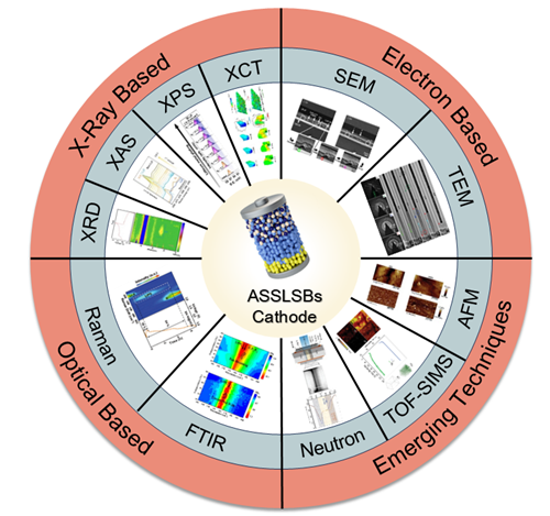
All-solid-state lithium-sulfur batteries (ASSLSBs) are regarded as one of the most promising next-generation energy storage systems due to their ultrahigh theoretical energy density (2600 Wh/kg) and enhanced safety. Current bottleneck issues primarily stem from the sluggish redox kinetics and mechanical degradation of sulfur-based cathodes in solid-state systems. Therefore, developing advanced characterization techniques to elucidate the behavior of sulfur cathodes in solid-state configurations is crucial for optimizing battery design and enhancing performance. This review summarizes recent research progress in advanced characterization technologies for cathode development in all-solid-state Li-S batteries. Through representative case studies, it comprehensively explores how X-ray, electron, optical, and other emerging techniques reveal the sluggish kinetics and degradation mechanisms of sulfur-based cathodes, providing guidance for high-performance cathode design. Finally, the article prospects future development directions of characterization technologies in solid-state Li-S battery cathodes and summarizes current challenges, offering valuable insights and references for future research endeavors.

Contents

1 Introduction

2 X-Ray related techniques

2.1 XRD

2.2 XAS

2.3 XPS

3 Electron related techniques

3.1 SEM

3.2 TEM

4 Optical related techniques

4.1 Raman

4.2 FTIR

5 Other emerging characterization techniques

5.1 AFM

5.2 TOF-SIMS

5.3 Neutron related techniques

5.4 XCT

6 Conclusion and outlook

Cite this article

Jiawei Li , Guobao Xu . Applications and Challenges of Advanced Characterization Techniques in All-Solid-State Lithium-Sulfur Battery Cathodes[J]. Progress in Chemistry, 2025 , 37(12) : 1846 -1865 . DOI: 10.7536/PC20250515

1 Introduction

Based on the urgent global demand for clean, renewable energy in the context of the global energy transition, high specific energy density secondary battery technologies have become a research focus in the field of electrochemical energy storage[1-2]. All-solid-state lithium-sulfur batteries (ASSLSBs), with their high theoretical specific capacity (1675 mAh·g-1) and energy density (2600 Wh·kg-1), are regarded as one of the most promising next-generation energy storage systems. By means of a synergistic design involving a lithium metal anode, solid-state electrolytes (SSEs), and a sulfur-based cathode, this system not only effectively suppresses the polysulfide shuttle effect prevalent in conventional liquid systems but also fundamentally reduces the risk of thermal runaway[3]. However, the actual performance of ASSLSBs still falls far short of theoretical expectations, with key bottlenecks lying in the sluggish kinetics of the sulfur cathode within the solid-state system and interfacial mechanical failure. These issues include low ionic conductivity of the active material, electrode structural degradation caused by the large volume expansion of sulfur (~80%), discontinuities in the electron/ion transport network, and capacity fade induced by side reactions at the solid–solid interface[4-6]. The root causes of these problems are closely linked to the microstructural evolution of the sulfur cathode, its interfacial chemical behavior, and its charge transport mechanisms. Therefore, the development of advanced characterization techniques to elucidate the behavior of the sulfur cathode in solid-state systems is crucial for optimizing electrode design and enhancing battery performance[7].
Characterization techniques can be categorized into two types based on experimental conditions: ex situ and in situ (or operando). The former involves static sampling to analyze the final state of electrode reactions, while the latter employs real-time, synchronous monitoring to dynamically resolve the structural evolution of electrodes and the mechanisms of interfacial reactions during electrochemical processes. It is important to note that “operando” characterization specifically refers to dynamic monitoring under continuous charge–discharge conditions, with a technical scope consistent with in situ characterization. Although ex situ techniques can reveal the overall electrochemical behavior of electrode materials, they have inherent limitations in studying dynamic reaction mechanisms: First, transient processes such as interfacial passivation in sulfur-based electrodes occur on sub-second timescales and are highly sensitive to electrochemical parameters like the voltage window and current density; static testing struggles to capture their dynamic evolution paths. Second, the intrinsic chemical instability of sulfur species (e.g., their high reactivity toward O₂/H₂O) can easily trigger secondary reactions during sample transfer, leading to test results that deviate from the true electrochemical process[89]. In contrast, in situ characterization, by employing closed testing systems, enables real-time tracking of the evolution of the electrode–electrolyte interface and the establishment of quantitative structure–property relationships between structural parameters (such as lattice strain and interfacial impedance) and electrochemical performance (such as capacity fade rate and polarization voltage), thereby providing crucial guidance for optimizing electrode materials and interface design.
The current mainstream characterization technology platforms—comprising three major traditional characterization modules based on X-ray technology, electron-based microscopy, and optical-spectroscopic principles—provide complementary structural and morphological analyses of sulfur-based cathode behavior from the atomic to the microscale[10-13]. On the other hand, emerging multimodal approaches—including atomic force microscopy (AFM), time-of-flight secondary ion mass spectrometry (TOF-SIMS), neutron depth profiling (NDP), and X-ray computed tomography (XCT)—leverage their advantages in spatial resolution and chemical sensitivity to further elucidate the interfacial reaction kinetics and elemental distribution patterns of the cathode[14-17]. In addition, specially designed in-situ cells can be used to track in real time the evolution of structural morphology during cycling. However, in-situ characterization of sulfur-based cathode systems faces a dual challenge: (1) sulfur-based active materials are prone to chemical degradation under high-energy X-ray or electron beam irradiation, leading to signal distortion; (2) solid–solid interfaces are deeply embedded within composite electrodes, and conventional characterization techniques (such as TEM and XPS), limited by penetration depth (<10 nm) and spatial resolution, struggle to accurately resolve the chemical evolution of subsurface interfaces. Overcoming these bottlenecks requires integrating cutting-edge technologies such as cryo-electron microscopy and synchrotron radiation sources to enable multi-scale, high-precision observations[18-19].
This article reviews the latest research advances in cathode characterization techniques for ASSLSBs in recent years. By combining typical examples, it elucidates how X-ray, electron, optical, and other emerging technologies provide a scientific basis for cathode optimization strategies by revealing underlying mechanisms related to mechanical degradation and slow redox kinetics. In addition, the article looks ahead to future development directions, such as integrated multi-technique characterization and AI-assisted data analysis, and summarizes the current technical bottlenecks of characterization techniques in cathodes, with the aim of providing theoretical support for the design and optimization of high-performance ASSLSBs cathodes.

2 X-ray-based characterization techniques

X-ray techniques constitute a powerful suite of tools for studying the properties of electrode materials. X-ray characterization techniques provide information on electronic and crystal structures through scattering, spectroscopy, and imaging methods. Currently, these primarily include spectroscopic techniques such as X-ray diffraction (XRD), X-ray absorption spectroscopy (XAS), and X-ray photoelectron spectroscopy (XPS), as well as imaging techniques such as transmission X-ray microscopy (TXM), scanning transmission X-ray microscopy (STXM), and coherent X-ray diffraction imaging (CXDI). It is worth noting that although X-ray imaging techniques have been applied in liquid lithium-sulfur batteries[20],their application across the broader solid-state Li-S system remains limited. This is due to sulfur's low X-ray absorption cross-section, which results in insufficient signal intensity and makes it difficult to obtain high-resolution characterization results. In contrast, techniques such as XRD, XAS, and XPS provide a wealth of critical information for research on all-solid-state lithium-sulfur battery cathodes. Therefore, this article will focus on introducing the research on solid-state Li-S cathodes using three key characterization techniques: XRD, XAS, and XPS.

2.1 X-ray diffraction

As a crystal-structure-sensitive characterization technique, XRD is widely used in compositional and elemental distribution analysis and is an important tool in materials research. It can be used to determine the phase composition and crystallinity of materials[21-22].
In all-solid-state lithium-sulfur batteries, the extremely low ionic conductivity of S and Li2S severely limits the battery's performance. Extensive efforts have been made in the past to address the conductivity issue. XRD, as the most widely used tool, provides information on structure and phase formation, aiding in the development of new electrolytes and the investigation of factors influencing electrode kinetics. Non-in situ XRD can detect the formation of new phases, offering crucial insights into the development of high-ion-conductivity electrolytes. Kamaya et al.[23]used non-in situ synchrotron XRD and discovered that the reaction product forms a new phase with a tetragonal unit cell, whose structure differs from any previously reported superionic conductor. Combined with neutron diffraction results, the composition of the new phase was determined to be Li10GeP2S12. Experiments have demonstrated that this novel electrolyte exhibits an ionic conductivity of 12 mS·cm-1at 27 ℃. In addition, the influence of the three-phase ratio within the electrode on kinetics has been investigated. Hosseini et al.[24]studied the performance of copper sulfide–carbon–sulfide (CuSS) composites with three different ratios as the composite cathode in ASSLSBs, and non-in situ XRD revealed that the enhancement of electrode conductivity is directly associated with the formation of the Cu phase. Based on this characteristic, they concluded that the CuSS(2-1) cathode, rich in CuS, exhibits the best redox performance.
The above ex situ studies investigated the source of high ionic conductivity by comparing the crystal phase changes of materials before and after cycling; however, the intermediate electrode energy storage mechanism remains unclear, which hinders the development of novel high-conductivity cathodes. By using in situ XRD to track phase transformations in real time, the ion transport mechanism in sulfur-based cathodes can be elucidated. For example, using synchrotron-based XRD, it was first revealed that the high ionic conductivity of the Li2S–LiI–MoS2 cathode originates from the in situ formation of a conductive LiI phase during discharge[25]. In addition, the influence of particle size on the conductivity of MoS2 has been explored. Cook et al.[26] compared the lithiation behavior of MoS2 with different particle sizes and concluded that bulk MoS2 undergoes an irreversible first-order phase transition, whereas the phase transition process in nano-MoS2 is significantly suppressed, which facilitates the formation of fast lithium-ion transport channels. On the other hand, the interfacial compatibility between TiS2 electrodes and LiBH4 has also been studied. Kharbachi et al.[27] showed that due to the strong reducing power of LiBH4, the intermediate phase generated by gas desorption can form a stable interface, further suppressing the solid-state reaction between TiS2 and LiBH4 while allowing lithium-ion conduction and charge-transfer reactions. In addition, in-depth research has been conducted on composite electrodes at low temperatures. Zhao et al.[28] used in situ XRD characterization to elucidate the phase transitions of the S7Se0.5Te0.5 (SST) cathode at low temperatures (Figure 1). When discharged to 20% DoD, a signal peak corresponding to crystalline Li2S appeared in the contour plot, indicating that the SST cathode with short-chain molecules facilitates the binding of Li+, thereby forming the Li2S phase. Combined with the analysis of the three-dimensional structural evolution of the electrode at low temperatures using synchrotron radiation XCT, it was found that after charging to 3.0 V, the expanded active material reverted to a uniformly distributed fine-particle state. This demonstrates that SST materials exhibit excellent structural reversibility under low-temperature conditions. The above studies indicate that using in situ diffraction techniques to track phase transitions in electrode materials is conducive to gaining a deeper understanding of the electrode energy storage mechanisms that give rise to high ionic conductivity.
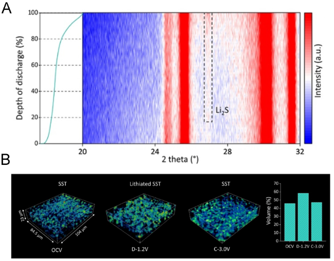
图1 (A) 低温下SST复合阴极的原位XRD图;(B)同步辐射X射线断层扫描重建与体积渲染显示了低温SST复合阴极的三维微观结构

Fig.1 (A) In situ XRD patterns of SST composite cathode at low temperature. (B) Synchrotron X-ray tomography reconstruction with volume rendering shows the 3D microstructure of the low-temperature SST composite cathode[28]. Copyright 2025, Wiley

Energy-dispersive X-ray diffraction (EDXRD) is a synchrotron-based technique that can provide structural information from within intact samples, such as batteries. This is because the incident X-ray beam can penetrate the battery casing, enabling tomography-like diffraction mapping within the bulk material. By using a polychromatic beam, diffraction patterns can be rapidly collected without changing the scattering angle, with a spatial resolution of up to tens of micrometers. This technique can be used to study the mechanical degradation process of cathodes. Sun et al.[29]used EDXRD technology to track the evolution of the unit cell in composite materials (Figure 2). The results show that Li6.6Ge0.6Sb0.4S5I undergoes lattice collapse below 0.7 V (manifested as a decrease in crystallinity and an increase in the d-spacing), which to some extent hinders ion transport. In addition, this technique has been applied to the study of macroscopic mechanical fracture[30-31]; in such studies, it is typically combined with XCT technology to capture volumetric changes. For example, EDXRD-XCT technology has been used to study the volume evolution of the Li-In anode in Li-S systems[30]. It was found that during charging, the original diffraction lines of In disappear, replaced by In-Li diffraction peaks. Furthermore, the volume change of lithium metal leads to the accumulation/release of stress at the electrode-electrolyte interface, thereby causing mechanical degradation of the electrode.
图2 EDXRD观测半电池和全电池的结果,包括Li-In负极和FeS2正极。(A) 半电池;(B) 全电池

Fig.2 EDXRD result of half-cell and full cell, including Li-In anode and FeS2 cathode. (A) half-cell; (B) full cell[29]. Copyright 2021, Wiley

However, the current application of in-situ XRD technology in solid-state lithium-sulfur batteries still faces several challenges. During the composite reaction involving sulfur, the formation of amorphous structures by sulfur species[32-33]limits real-time tracking of its phase transition process. Moreover, high-energy X-rays from synchrotron sources can easily cause structural damage and morphological degradation of sulfur-based materials[34], further compromising the reliability of in-situ characterization. To address these issues, non-destructive spectroscopic techniques such as Raman spectroscopy[35-36]not only enable dynamic monitoring of chemical state changes in sulfur species but also help mitigate sulfur-related damage. Notably, recently developed pair distribution function (PDF) technology has provided a new approach for analyzing the local structural distribution of amorphous sulfur[37]. By analyzing short-range order information from total scattering data, this technique has successfully revealed the evolution of sulfur's atomic distribution in all-solid-state lithium-sulfur systems.

2.2 X-ray absorption spectroscopy

XAS, with its element-specific resolution, can precisely track the evolution of the electronic structure, chemical bond reconfiguration, and valence state fluctuations of specific elements during cycling, making it a key tool for elucidating the physicochemical properties of sulfur electrodes. Based on energy range, XAS spectra are divided into X-ray Absorption Near-Edge Structure (XANES) and Extended X-ray Absorption Fine Structure (EXAFS)[38]:The former analyzes the oxidation state and coordination environment of the absorbing atom, while the latter reveals short-range order features at the atomic scale (such as coordination number, bond length, and the chemical properties of neighboring atoms).
Since sulfur undergoes ring-opening reactions during reduction, leading to changes in its oxidation state[39],XANES analysis helps to investigate the electrochemical reduction mechanism of the sulfur cathode[40-41]. Xiao et al.[42]conducted ex situ XANES analysis on solid-state lithium–sulfur batteries based on a sulfide electrolyte (Li3PS4). Their results indicate that sulfur undergoes a stepwise reduction process without disproportionation. Initially, long-chain polysulfides (S6 2-) are formed, which are subsequently reduced to medium-chain polysulfides (S4 2-) and short-chain polysulfides (S2 2-), ultimately being reduced to Li2S. Cao et al.[43]used synchrotron radiation XANES in combination with in situ Raman spectroscopy and found that the conversion from S to Li2S involves an metastable intermediate phase, Li2S2(Figure 3). They also concluded that due to slow solid–solid transformations and charge transfer, the transitions among S8, Li2S2, and Li2S exhibit sluggish reaction kinetics in ASSLSBs, resulting in underutilization of S8. On the other hand, Kim et al.[44]observed through sulfur K-edge XANES that during discharge in S/LGPS solid-state cathodes, the peak intensities of Li2S and Li2S2change synchronously, demonstrating that the discharge products in ASSLSBs are actually a mixed phase of Li2S and Li2S2, rather than the traditionally assumed single-phase Li2S. Furthermore, the study found that promoting the formation of discharge products primarily composed of Li2S2can enhance the initial discharge capacity, electrochemical reversibility, and cycle stability of ASSLSBs.
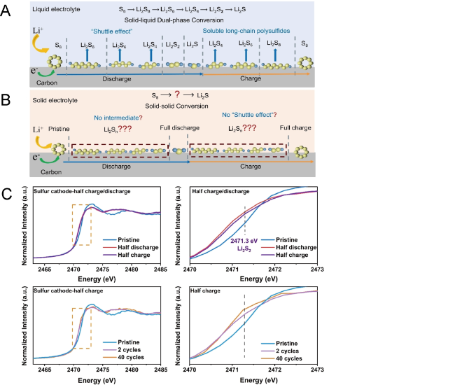
图3 锂硫电池反应机理对比以及XAS的表征结果。(A)液态锂硫电池的反应机理;(B) 固态锂硫电池的反应机理;(C) 基于同步加速器的非原位S K-边XANES解析全固态锂硫电池正极反应机理结果

Fig.3 Electrochemical reaction mechanisms of S8 in (A) liquid electrolyte and (B) solid electrolyte. (C) Understanding the reaction mechanism of ASSLSBs cathode through ex situ synchrotron sulfur K-edge XANES[43]. Copyright 2023, Wiley

The multiple sulfur reduction mechanism experiments mentioned above reveal the limited reaction kinetics in solid-state lithium–sulfur cathodes. Based on the concept of redox chemistry, recent studies have successfully enhanced the kinetics of the Li2S cathode using AQT redox mediators, and operando XANES has been used to elucidate its oxidation mechanism[45]. On the other hand, the use of single-atom catalysts to promote sulfur reduction kinetics is currently a research hotspot[46].
XAS combined with wavelet transform (WT) can be used to distinguish adjacent specific interactions in k- and R-space[47].This technique is particularly well-suited for developing single-atom catalysts. Cao et al.[48], based on EXAFS-WT combined with DFT calculations, propose that the optimal coordination configuration for a Fe single-atom catalyst is Fe-N2B2-1 (Figure 4). In combination with XPS characterization results, it is concluded that coordination between the less electronegative iron and boron atoms modulates the electron density at the Fe center. More importantly, this optimized electronic structure provides a satisfactory adsorption energy for intermediates and Li2S, and enhances the redox kinetics during the SRR/SOR process.
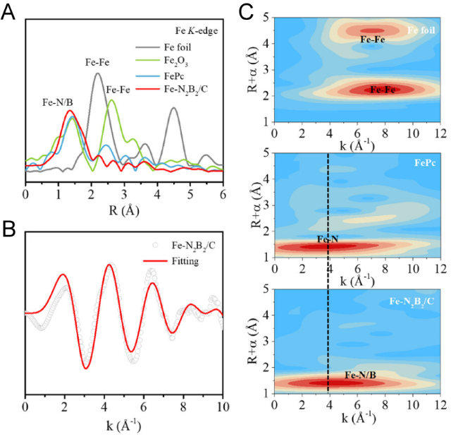
图4 基于小波变换的EXAFS的表征结果。(A) 对铁箔、Fe2O3、FePC和Fe-N2B2/C的FT-EXAFS;(B) Fe-N2B2/C的原始和拟合k空间;(C) Fe箔、FePc和Fe-N2B2/C的小波变换图像

Fig.4 The characteristic results based on FT-EXAFS. (A) FT-EXAFS of Fe foil, Fe2O3, FePc, and Fe-N2B2/C; (B) raw and fitted k space of Fe-N2B2/C; (C) wavelet transform images of Fe foil, FePc, and Fe-N2B2/C[48]. Copyright 2025, Wiley
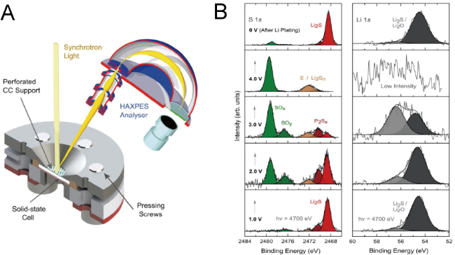
On the other hand, understanding the charging mechanism of all-solid-state lithium-sulfur batteries can provide an important theoretical basis for improving their operational performance. However, this research area remains largely unexplored. Some studies have already shown that the conversion efficiency during the charging process is below 90%[49-50],but there is still no consensus on the underlying mechanisms. XAS is an ideal tool for identifying sulfur species formed during charging, as it offers strong elemental resolution and is highly sensitive to changes in oxidation states. However, during actual charging, side reactions such as sulfur isomerization (e.g., the formation of chain-like sulfur species in addition to cyclic S8) and decomposition of the solid electrolyte (e.g., oxidation of sulfide electrolytes) may occur. These secondary factors significantly interfere with XAS’s ability to accurately identify sulfur species. Recently, some studies have used in-situ Raman spectroscopy combined with DFT calculations to predict the reaction pathways in Li-S batteries via thermodynamic pathways[51]. The approach employed in this work can be adapted for XAS characterization, thereby reducing the reliance of conventional XAS on high precision. However, theoretical models struggle to fully capture the potential side reactions occurring in real-world systems. Therefore, developing high-precision XAS techniques (such as those based on fourth-generation synchrotron radiation sources) remains a central focus of current research.

2.3 X-ray Photoelectron Spectroscopy

Thanks to its ultra-high surface sensitivity, XPS has become a core characterization technique for analyzing the surface chemical evolution, redox state transitions, and electronic structure reconstruction of solid-state battery materials. It can also be used in depth profiling mode, where the sample is sequentially sputtered while XPS spectra are collected, enabling the study of material properties at different depths.
The study by Ohno et al.[52]indicates that the degradation of SSE in the cathode increases interfacial impedance, reduces the lithium-ion transport capability of solid-state Li-S batteries, and hinders the reaction kinetics at the cathode. In recent years, ex-situ XPS combined with other characterization techniques has been used to investigate the electrochemical and thermodynamic transformation processes of sulfide-based solid electrolytes[53-56].However, during sample preparation and transfer, side reactions or other material transformations may introduce ambiguity into the results of ex-situ experiments. Therefore, it is essential to employ in-situ XPS to provide a new perspective on the degradation mechanisms of solid electrolytes.
Koerver et al.[57]used in-situ XPS to probe, from the back side within the XPS chamber, composite electrodes containing SSE and C in Li3PS4SSE. They found that the SSE decomposes to form redox-active species, and that when the charging voltage exceeds 4.3 V, a nanoscale degradation layer forms at the C/LPS interface. The thickness of this layer is positively correlated with the cutoff voltage, severely limiting battery performance. Wood et al.[58]developed a method to study the chemical evolution of the Li-LPS interface by creating "virtual electrodes." They used an electron gun to direct an electron flux onto the SSE surface, thereby effectively generating a negative bias at the interface. OperandoXPS revealed that the Li2S phase forms first and subsequently evolves into a layered configuration within the SEI. However, although the above-mentioned in-situ XPS can provide detailed insights into material decomposition, these battery designs often differ significantly from real-world operating conditions. To address this, Wu et al.[59]presented an in-situ battery design that can accommodate external stacking pressure during operation. In the voltage range above 2.1 V, they captured the formation of oxidation by-products of Li3PS4, providing direct evidence for the oxidative degradation pathway of sulfide electrolytes.
It is worth noting that the probing depth of conventional XPS (~10 nm) is insufficient to access deeply buried interfaces. To address this, hard X-ray photoelectron spectroscopy (HAXPES) extends the probing depth to 50–100 nm by increasing the inelastic mean free path of photoelectrons, and combines angle-resolved techniques to enable depth profiling of deeply buried interfaces[60].Recently, Aktekin et al.[61]used in-situ HAXPES to reveal the dynamic decomposition mechanism of the sulfide electrolyte Li6PS5Cl (Figure 5). The study shows that its electrochemical decomposition begins at 1.75 V (vs Li+/Li), with Li2S and Li2O being the dominant products in the 1.5–1.0 V range. Upon further polarization to 2–4 V, Li2O and Li2S are oxidized into sulfites and polysulfides, after which subsequent lithium deposition can reversibly restore the initial SEI components.
图5 原位HAXPES的示意图(A)和表征结果(B)

Fig.5 (A) Schematic illustration of the operando HAXPES measurement. (B) Normalized HAXPES detail spectra evolution during polarization to high potentials[61]. Copyright 2024, ACS

On the other hand, in situ XPS imaging, as an emerging technique, provides a unique perspective for investigating the mechanisms of electrolyte decomposition. This technique can acquire high-resolution core-level spectra of key elements while simultaneously offering spatially resolved morphological imaging and chemical composition analysis. Nandasiri et al.[62]were the first to develop in situ XPS imaging and apply it to SPE-based solid-state Li-S batteries (Figure 6). The imaging results revealed that parasitic reaction products (fluoride and sulfide anions) undergo cross-interactions with the adjacent electrolyte and nucleate to form the SEI layer. This phenomenon is manifested as aggregation in the XPS images, and the chemical trapping of dissolved polysulfides at the top of the lithium anode substrate leads to electrolyte fouling.
图6 (A) 原位XPS成像的示意图和(B) 表征结果

Fig.6 (A) Schematic diagram of the XPS sample holder developed for battery cycling and in situ XPS characterization. (B) XPS chemical imaging of the Li-electrolyte interfacial region after first charging cycle and first discharging cycle[62]. Copyright 2017, ACS
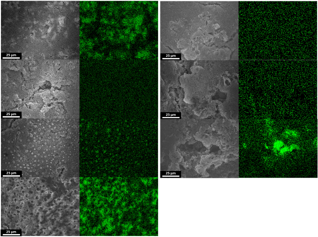
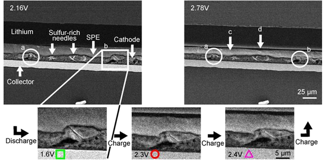
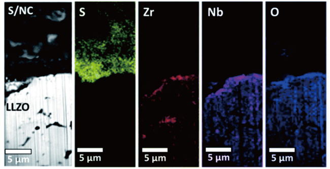
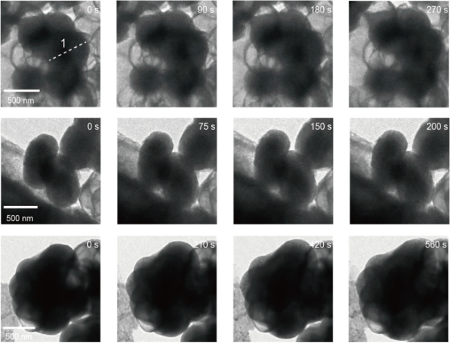
3 Electronic-based characterization techniques

3.1 Scanning Electron Microscopy

Scanning electron microscopy (SEM) can be used on most materials and offers a higher spatial resolution than optical microscopy (several nanometers). SEM can provide elemental information and crystallographic details through energy-dispersive X-ray spectroscopy (EDS) and electron backscatter diffraction (EBSD), respectively[63-64],making it a core tool for characterizing sulfur-based cathodes. SEM imaging requires that samples be placed in a vacuum chamber and have an exposed surface where the electron beam can perform raster scanning. During this process, sulfur-based cathodes may be damaged by the high-energy electron beam, so it is essential to monitor and control electron-beam-induced damage.
In ASSLSBs, the conversion reactions of the cathode active material lead to significant volume changes, with internal stresses accumulating prominently at the three-phase interface, thereby causing severe electrochemical-mechanical failure of the electrode. Ex situ scanning electron microscopy is widely used to evaluate the surface morphology, phase distribution, and microstructure of electrodes after mechanical failure. Ohno et al.[65]demonstrated that the particle size of the active material has a critical impact on the volume change of the composite cathode. SEM images show that the substantial volume expansion occurring during discharge results in a dense morphology in the hand-ground cathode. Conversely, during charging, the volume contraction of the active material creates gaps between the active material and the surrounding dense matrix, leading to loss of interfacial contact. In contrast, the ball-milled electrode with smaller particle sizes does not exhibit any obvious morphological changes. Oh et al.[66]suggested that electrolyte decomposition also contributes to crack-induced failure of the S cathode. SEM-EDS observations of the phase distribution at the Li-Si|Li2S-P2S5 three-phase interface revealed lithium-enriched regions within the SSE, formed during the plating process under high cutoff voltages. They attributed this phenomenon to electrochemical decomposition of the SSE at high cutoff voltages, which induces lithium dendrite growth. The crack-induced failure of the S cathode was attributed to microshort circuits caused by lithium dendrite growth within the SSE. On the other hand, Zou et al.[67]investigated the microstructure of FeS2-based cathodes after mechanical failure. They found that during lithiation, FeS2 nanorods undergo anisotropic volume expansion, and stress concentration triggers crack initiation at the base. SEM images reveal a trend toward fragmentation and pulverization within the FeS2 particles, a pulverization process that leads to poorer electrical contact and accelerates the degradation of cycling performance.
It is worth noting that the dynamic tracking capability of in-situ SEM can provide deeper mechanistic insights into the stress failure modes of sulfur-based cathodes. For example, Zhang et al.[68]used in-situ SEM combined with energy-dispersive spectroscopy to observe the volume expansion and stress evolution of the sulfur cathode during operation (Figure 7). Their findings indicate that the stress generated during the initial cycles is primarily associated with the nucleation and growth of solid Li-S phases, leading to structural rearrangements. In contrast, subsequent cycles are characterized mainly by elastic mechanical behavior. In other studies, this approach has been employed to investigate failure modes in SPE-based cathodes[69-70]. Marceau et al.[70]observed that the discharge products of the S cathode form needle-like deposits, which grow predominantly at the interface between the electrolyte and the electrode (Figure 8). This leads to an increase in cathode porosity and accelerates failure. The contrasting differences observed in the SPE suggest that polysulfides irreversibly dissolve into the electrolyte, resulting in a decline in battery capacity.
图7 硫阴极在第一个周期内不同充电状态下的原位SEM和EDS图像

Fig.7 In situ SEM and EDS images of a sulfur cathode at different states of charge during the first cycle[68]. Copyright 2019, Wiley

图8 基于SPE的Li-S电池在放电和充电状态下的原位SEM图像

Fig.8 In situ SEM images of the Li-S cell based on SPE in the discharged and charged state[70]. Copyright 2016, Elsevier

In summary, the predictive power of existing scoring systems for bleeding events is limited, and their results are inconsistent[25,30,33].
图9 LLZO SE 与循环电池的S/NC阴极之间的横截面FIB-SEM 图像和元素分布图

Fig.9 Cross-sectional FIB-SEM image and elemental map of the interface between LLZO SE and the S/NC cathode of the cycled cell[73]. Copyright 2020, Royal Society of Chemistry

Due to the destructive nature of FIB-SEM, it is essentially a non-in situ characterization technique. Recently, Perrenot et al.[75]designed an operando FIB-SEM system that, for the first time, enabled real-time observation of NMC composite electrodes during charge and discharge. This achievement has instilled great hope for the in situ application of FIB-SEM. In addition, FIB-SEM characterization can be further used for 3D tomographic visualization. Continuous milling of thin slices combined with interleaved scanning electron microscopy imaging can generate a library of 2D images, which can then be assembled into a 3D dataset. This approach allows for quantitative analysis of parameters such as porosity and surface area of cathode materials[76]. Notably, image segmentation can also quantify the evolution of different microstructural features; thus, FIB tomography has also been employed to investigate how mechanical effects-induced changes in electrode microstructure affect ion transport[77-78]. However, due to the relatively low elemental contrast within sulfur-based composite cathodes, the tomographic imaging capability has not been widely adopted for characterizing cathodes in ASSLSBs.

3.2 Transmission electron microscopy

TEM, with its atomic-level spatial resolution and electron structure analysis capabilities, occupies an irreplaceable position in the field of micro-characterization of battery materials. It is worth noting that most TEM studies do not use complete nanobatteries; instead, they employ designed experiments to focus on a single phenomenon, such as studying the electrochemical lithiation process of sulfur-based cathodes (Figure 10) [79]. These experiments avoid the lengthy and complex assembly process of nanobatteries while still providing crucial information about nanoscale phenomena within the cathode. The experimental setup for TEM remains largely consistent across most studies, typically including a sample holder equipped with a working electrode. The tip of the sample holder contains a lithium metal anode, and the Li2O formed in situ on the lithium metal surface is usually used as a solid-state electrolyte, as it effectively conducts ions and has minimal impact on the experimental results. This transformation has made what was once a highly challenging TEM experiment feasible.
图10 电化学装置示意图,用于对纳米封闭S阴极的电化学锂化作用进行原位TEM观察

Fig.10 Schematic illustration of the electrochemical device set up for a real-time TEM observation of an electrochemical lithiation of nanoconfined S cathodes[79]. Copyright 2015, Wiley

A key area of TEM characterization is elucidating the working mechanism and lithiation properties of sulfur cathodes. Kim et al.[79]used in-situ STEM-EELS to demonstrate that CNT nanoreactors effectively dissipate heat and suppress sulfur sublimation under high-energy electron beam irradiation in TEM. They showed that during lithiation, S forms Li2S,and the smooth reaction process and constant reaction rate are attributed to the high ionic conductivity at the grain boundaries of the nanocrystalline Li2S. Yang et al.[80]combined in-situ TEM imaging, ADF-STEM imaging, SAED, and EELS techniques to observe phase separation between S and Li2S and found no polysulfides. This confirms that sulfur undergoes a phase transition to Li2S under solid-state conditions without the evolution of intermediate lithium polysulfides. These two studies, using multi-modal in-situ TEM characterization, demonstrate that the formation of nanocrystalline Li2S provides a medium for ion and electron transport into the Li2S/S interface, offering insights into the reaction kinetics of sulfur cathodes. However, the in-situ TEM results from Xu et al.[81]indicate that lithium diffusion primarily occurs at the surface of sulfur particles, and the insulating Li2S shell that forms hinders Li+ penetration into the material's interior, leading to a significant decline in battery capacity.
The above-mentioned discrepancies in conclusions suggest that the idealized conditions of laboratory simulations may influence experimental results. Therefore, it is highly necessary to introduce multiple influencing factors (such as temperature variations) to obtain a more accurate mechanistic understanding. In recent years, microelectromechanical systems (MEMS) combined with TEM to simulate in-situ imaging under different temperature conditions have emerged as a promising approach[82].Wang et al.[83]reported the precipitation and decomposition of Li2S at elevated temperatures using a MEMS heating device in an in-situ open-aperture TEM configuration (Figure 11). They found that even further experiments conducted on samples with enhanced conductivity did not trigger the decomposition of Li2S, indicating that electrical conductivity is not the primary limiting factor for the decomposition of Li2S during charging. At 150 ℃ and a bias voltage of 3 V, Li2S underwent delithiation, while at 300 ℃, a more complete delithiation process occurred, suggesting that the slow diffusion rate of lithium ions is a critical step determining the reversibility of Li2S. This study also showed that highly crystalline Li2S was formed at temperatures as high as 800 ℃ and did not decompose even under a bias voltage of 8.0 V, indicating that high crystallinity is another factor contributing to the irreversibility of Li2S.
图11 (A) 固态Li-S电池的设计方案,其中配有用于原位TEM观察的MEMS加热装置;(B) S@CNT正极的锂化/去锂化过程

Fig.11 (A) A scheme showing the setup of the solid cell implemented with a MEMS heating device for in situ TEM observation. (B) Lithiation/delithiation process of the S@CNT[83]. Copyright 2020, Wiley

Another key area of TEM characterization is the study of volume changes in cathodes during lithiation, providing a new perspective on addressing mechanical degradation of electrodes due to stress concentration. Yu et al.[84]attached a Li-Li2O metal contact to a tungsten probe, brought it into contact with a Li2S-Li xIn2S3cathode, and applied a bias voltage to observe the cathode lithiation process. During delithiation/lithiation, the Li2S-Li xIn2S3exhibited volume changes of only 1.9% and 3.3%, respectively. In addition, for the electrochemical-mechanical behavior of nanomaterials, the use of a dual-probe electrostatic biasing stage often enables more precise positioning and reduces interference from surrounding regions[85-86]. Based on in-situ TEM characterization using a dual-probe stage, it was found that Li+ions flow through the Li2O solid electrolyte layer and react with the sulfur cathode encapsulated by MoS2. The S particle size expanded by only 33%–48% (Figure 12). This phenomenon can be attributed to the hollow structure of the S spheres, which provides additional space, and to the highly flexible MoS2nanosheets[87]. To investigate the correlation between electrochemical performance and volume expansion, Xu et al.[88]used in-situ TEM to examine the lithiation behavior of a porous carbon nanofiber/sulfur electrode. They found that the formation of lithiation products is closely related to the mechanical stability of the carbon host, and that microporous structures are more favorable than mesoporous structures for ion transport and for mitigating volume expansion.
图12 基于原位 TEM 研究的 MoS2-封装空心硫球中的锂扩散现象

Fig.12 Lithium diffusion phenomenon in MoS2-encapsulated hollow sulfur spheres based on in situ TEM study[87]. Copyright 2017, ACS

It is worth noting that most of the studies mentioned above were conducted under carbon-coating measures, as sulfur is highly sensitive to electron beams. Excitingly, cryogenic electron microscopy (Cryo-TEM, Cryo-FIB-SEM) can effectively suppress sulfur volatilization[89-90]. This is because cryogenic sample stages can cool the samples, thereby significantly enhancing the stability of sulfur-based materials under electron beam irradiation. Moreover, cryogenically prepared samples can preserve the structure extracted from the battery housing, thus preventing extraneous side reactions with the atmosphere. It is important to note that diffusion kinetics under cryogenic conditions are limited; therefore, cryo-electron microscopy is generally not suitable for in-situ studies. However, it may enable the observation of kinetic information that would be unprecedented under normal conditions. In ASSLSB cathodes, Cryo-(S)TEM has been used to study the microstructural evolution and lithiation mechanisms of MoS2electrodes during cycling[19,91]. Cryo-electron microscopy results indicate that single-layer and double-layer MoS2exhibit different crystal structures (Figure 13), which also accounts for the performance differences between the two[19]. Currently, Cryo-FIB-SEM is being used to observe the phase distribution in S/LPS cross-sections[67]. Future research should aim to visualize nanoscale chemical and structural details. If in-situ or ex-situ TEM characterization of sulfur-based cathodes in solid-state systems proves infeasible, cryo-electron microscopy may help bridge this critical technological gap.
图13 单层和双层MoS2的环形暗场Cryo-STEM图像

Fig.13 High-resolution annular dark-field Cryo-STEM images of monolayer and bilayer MoS2[19]Copyright 2019, Wiley

4 Optical-based characterization techniques

4.1 Raman spectroscopy

Raman spectroscopy can sensitively detect microscopic structural changes such as crystal symmetry breaking, bond order reconfiguration, and lattice strain[92-93].In the study of lithium-sulfur batteries, Hagen et al.[94]were the first to establish an in-situ Raman characterization platform, successfully capturing the dynamic formation process of polysulfide radical anions during discharge. However, Raman technology faces significant interference from thermal effects: the local temperature rise induced by laser irradiation can trigger non-intrinsic side reactions, with a particularly pronounced impact on the solid-state interface of heat-sensitive sulfur electrodes. This technique presents a dilemma: while short-wavelength lasers can enhance scattering efficiency and reduce heat absorption, they also lead to a sharp increase in fluorescence background noise; conversely, high-power lasers can boost signal intensity but exacerbate thermal damage to the sample[95].
A large body of research has demonstrated that polysulfide (PS) shuttling also occurs in solid-state lithium-sulfur batteries based on SPE systems[96-97]. As mentioned earlier, compared to XRD's reliance on long-range ordered structures, Raman spectroscopy exhibits unique advantages in characterizing short-range ordered systems (PSs), effectively compensating for the shortcomings of traditional diffraction techniques[98]. Raman spectroscopy can be used to study the slow kinetics of polysulfides. Meng et al.[99]used in-situ Raman spectroscopy to monitor in real time the evolution of the sulfur cathode interface in SPE-based systems, confirming that PS deposition is attributable to the constrained dissolution-diffusion coupling within the SPE system: the slow mass transfer rate of PSs causes them to deviate from the main redox reaction pathway, ultimately depositing at the electrode interface in an electrochemically inert form. In addition, Raman spectroscopy, combined with techniques such as AFM, can be used to assess the impact of PSs on the SPE. Song et al.[97]found that after three cycles at 65 and 75 ℃, the resistance of the SPE was higher than that of the LSB before cycling, indicating a reduction in the SPE's ionic conductivity. The additional semicircle appearing in the high-frequency region of the electrochemical impedance spectrum can be attributed to the formation of a Li2S2/Li2S passivation layer. By combining ex-situ Raman spectroscopy with AFM, the authors concluded that the above-mentioned degradation phenomenon is attributable to the aggregation of nanofillers and the disappearance of SPE chains caused by the dissolution of PSs. It is worth noting that this issue arises only in the field of SPE-based solid-state lithium-sulfur batteries.
To mitigate the impact of the aforementioned PSs, developing high-temperature working electrodes to enhance reaction kinetics is a viable approach. Raman spectroscopy can be used to evaluate the high-temperature stability of polymer cathodes. Wang et al.[100]found through temperature-dependent Raman spectroscopy that the C—S and S—S bonds in Poly-SCN exhibit significant temperature-dependent behavior: at room temperature, only bond-length relaxation occurs, whereas at elevated temperatures, complete bond cleavage takes place. The material transitions from a glassy to a rubbery state at 77 ℃. In the rubbery state, the Poly-SCN cathode exhibits an ionic conductivity comparable to that of LPSCl electrolyte at 100 ℃. Moreover, SPAN cathode materials have become a current research focus due to their ability to completely suppress the formation of PSs, thereby fundamentally addressing the issues associated with PSs. However, SPAN also faces the problem of volume expansion arising from the formation of Li2S[101]. Recent studies have successfully suppressed the formation of Li2S by altering the SPAN reaction pathway[102], and in-situ Raman spectroscopy has been employed to elucidate the reaction mechanism. The in-situ Raman spectrum of solid-state SPAN (Figure 14) shows no significant change in the intensity of the peaks associated with the C—S bonds, indicating that the C—S bonds do not weaken during cycling. Combined with in-situ nuclear magnetic resonance (NMR) spectroscopy and theoretical calculation results, it has been verified that solid-state SPAN does not generate Li2S. This can be attributed to the strong interaction between residual DMF (high polarity) and Li+, which prevents the interaction between the C—S bonds in solid-state SPAN and Li+.
图14 固态SPAN在(A) 充电和(B) 放电过程中的原位拉曼光谱。(C) 液态SPAN在充电和放电过程中的非原位拉曼光谱

Fig.14 In situ Raman spectra of solid SPAN during (A) charge and (B) discharge. (C) Ex situ Raman spectra of liquid SPAN during charge and discharge[102]. Copyright 2022, Royal Society of Chemistry

More advanced Raman characterization techniques include Raman imaging, which achieves spatially resolved analysis of the chemical composition on a sample’s surface through grating scanning combined with a micrometer-sized laser spot[103],and is particularly suitable for elucidating the phase distribution in composite sulfur cathodes and revealing underlying mechanisms. Yang et al.[104]systematically investigated the microstructural component distribution in sulfur–carbon nanotube (S-CNT) composite cathodes using Raman imaging and found that at low and medium sulfur loadings, sulfur species are uniformly coated on the CNT surface; however, when the sulfur content is too high, sulfur tends to penetrate into the CNT interior, forming an amorphous sulfur phase that exhibits a stacking structure distinct from that of S8.Lang et al.[105]used in situ confocal Raman microscopy to reveal the redox reactions in Li–S batteries, confirming that the sub-steps of sulfur reduction and the polysulfide redox process follow first-order reaction kinetics (Fig. 15).Although the above studies were conducted in liquid lithium–sulfur systems, given that Raman imaging can simultaneously identify both sulfur and polysulfides and provide high-resolution imaging of their spatial distribution, with carefully designed experiments, this technique holds great promise for playing a significant role in studying the electrochemical behavior of the cathode in SPE-based all-solid-state lithium–sulfur batteries.
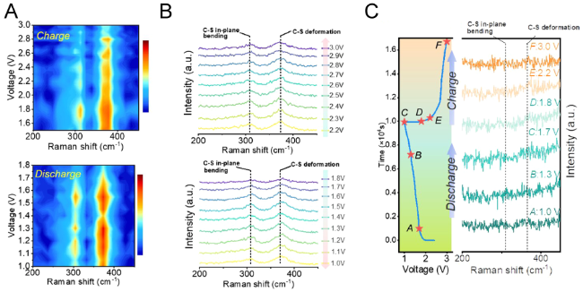
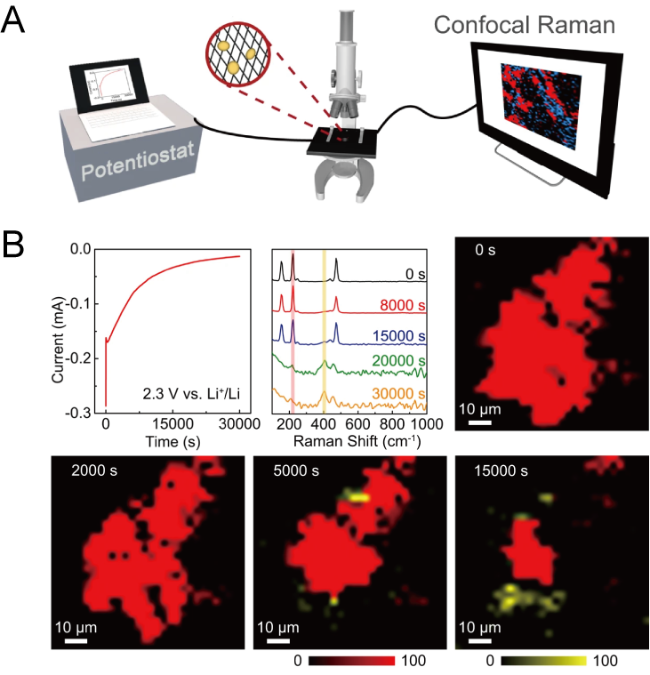
图15 (A) 用于探测Li-S电池氧化还原过程的机制和动力学的operando共焦拉曼显微镜实验装置示意图;(B) 硫电极在还原过程中的operando拉曼光谱和绘图图像

Fig.15 (A) Schematic illustration of the operando confocal Raman microscopy experimental setup for probing the mechanism and kinetics of Li-S redox processes. (B) Operando Raman spectra and mapping images of the sulfur electrode during reduction[105]. Copyright 2022, Springer Nature

4.2 Fourier Transform Infrared Spectroscopy

Fourier transform infrared (FTIR) spectroscopy is a non-destructive analytical technique based on molecular vibrational energy level transitions. Compared with traditional dispersive infrared spectroscopy, FTIR technology significantly enhances detection efficiency and data reliability through advantages such as rapid scanning, high signal-to-noise ratio, and excellent resolution. It has become an indispensable characterization tool for elucidating complex molecular structures and is currently widely used in characterization studies of organic compounds and polymer materials[106]. In the field of liquid Li-S batteries, FTIR spectroscopy is primarily used to study the degradation of electrodes and electrolytes[107-108]and to track polysulfides[109-110]. It is worth noting that the application of FTIR to the cathodes of ASSLSBs remains relatively limited, as Fourier transform infrared spectroscopy is more suitable for polymer materials.
In ASSLSBs, FTIR is used to study the composition of polymer electrodes after processing[111].For example, Shi et al.[112]used ATR-FTIR to investigate the thermal stability of the SPAN@LiFSI composite electrode and found that no new bonding vibrations emerged after heat treatment, indicating that no chemical reaction occurred between LiFSI and SPAN during the thermal process. The reduction in interfacial resistance at the cathode/LLZO electrolyte interface can be attributed to the filling of LiFSI particles, which enhances interfacial contact while preserving the integrity of the electrode structure. In addition, FTIR is more commonly used to elucidate the ion-conduction mechanism of SPEs. In their study of the "polymer-in-salt" electrolyte (PISE) system, Yang et al.[113]used FTIR vibrational mode analysis and found that the S-N-S bending vibration of TFSI-shifted from 650 cm-1 (PIS) to 646 cm-1 (PIS-AMW), demonstrating an interaction between the two. Combined with ex situ Raman spectroscopy, this indicates that the increased ionic aggregates in PIS-AMW directly lead to high ionic conductivity. Duan et al.[114]used ATR-FTIR to discover that during charge-discharge cycling, polysulfide dissolution in the PEO-LLZTO-Mg(TFSI)2 SPE system is significantly restricted, which is attributed to the formation of an insoluble magnesium composite layer at the cathode/CSE interface.
In situ FTIR technology is highly favored in the dynamic analysis of electrochemical processes due to its non-destructive and real-time monitoring capabilities. Some studies have used in situ techniques to track the evolution of the SEI during the thermal reaction of the LiBH4-S complex (Figure 16), revealing the unique chemical interactions between sulfur and hydrides as well as the formation pathway of the Li2B12H12intermediate[115]. However, in situ FTIR is still in its early stages, with one of the biggest challenges being the stringent configuration requirements for in situ cells. By taking into account the inherent characteristics of solid-state battery systems (such as high stacking pressure) and enhancing the infrared beam, it may be possible to develop an ideal in situ cell design that enables in situ characterization.
图16 (A) LiBH4+S和(B) 纯LiBH4的原位傅里叶变换红外光谱

Fig.16 In situ FTIR spectra of (A) LiBH4+ S; (B) pristine LiBH4[115]. Copyright 2022, Elsevier

5 Emerging Characterization Technologies

5.1 Atomic force microscopy

As a typical force-sensing characterization technique, AFM detects and amplifies atomic-level interaction forces between the probe tip and the sample surface via a microcantilever, enabling the analysis of surface morphology and material properties at the nanometer to atomic scale[116].However, atomic force microscopy still has certain limitations in practical applications. First, the technique requires exposing the sample surface; for in situ experiments, specially designed sample cells with exposed surfaces must be custom-built. Such designs, however, may deviate from the actual operating conditions of conventional all-solid-state batteries, making it difficult to accurately reflect their real-world performance. Similar to most high-resolution imaging techniques, AFM has a relatively limited field of view (typically only a few micrometers in each direction). More critically, AFM can only characterize the surface morphology of a sample and cannot directly probe the evolution of subsurface microstructures and chemical components. Despite these limitations, AFM remains one of the important tools for characterizing sulfur-based cathodes, providing not only surface morphology information but also enabling mechanical property measurements. In addition, other probe technologies based on AFM can be used to assess the charge behavior of electrodes[117-118].
The primary application of atomic force microscopy is to evaluate morphological evolution during cycling. Wan et al.[119]used in-situ electrochemical AFM (EC-AFM) to investigate the SEI formation and lithium insertion/extraction interface processes on ultra-flat monolayer MoS2electrodes (Figure 17). They found that the SEI film initially nucleates in isolated regions and forms a distinctive bilayer structure, which subsequently spreads across the entire electrode with a thickness of approximately 0.7 ± 0.1 nm, eventually accumulating to a thickness of 1.5 ± 0.7 nm. In addition, they observed that the stress generated during the phase transition in MoS2is ultimately relieved through the formation of a wrinkle-structured network. After the delithiation process is complete, these wrinkle networks remain at the interface, leading to reduced cycling efficiency and capacity fade in the battery.
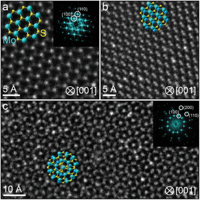
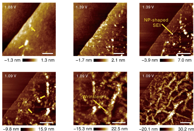
图17 通过原位原子力显微镜观察超平单层 MoS2/电解质界面的结构演变以及基于原子力显微镜测试A24和A19P5颗粒的形貌图像和杨氏模量等距分布

Fig.17 Structural evolution at the ultra-flat monolayer MoS2/electrolyte interface via in situ AFM. AFM-based testing of A24 and A19P5 pellets for topography images and Young's modulus areal distribution[119]. Copyright 2019, Springer Nature

In summary, existing scoring systems have limited predictive capabilities for bleeding events, and their results are inconsistent[25,30,33].
Many scanning probe microscopy (SPM) techniques, including Kelvin probe force microscopy (KPFM), atomic force microscopy–scanning electrochemical microscopy, and electrochemical strain microscopy (ESM), are variants of AFM and are used to assess charge activity behavior. KPFM operates without contacting the sample by generating a contact potential difference (CPD) between the cantilever and the sample. With its excellent surface electronic analysis capabilities, this technique has been used to observe the charge distribution after sulfur cathode engineering modifications. The results show that the electric field distribution in iPANI@rGO-CNT is uniform, demonstrating that this electrode facilitates the regulation of uniform ion flow and the suppression of Li dendrite growth[124].Mahankali et al.[125]combined AFM-SECM with in situ AFM and found that the conductive phase components in Li-S systems can undergo reversible phase transitions and participate in conversion reactions, while the insulating phase dominated by Li2S exhibits significant irreversible characteristics and is prone to side reactions with polysulfides (Figure 18).Electrochemical strain microscopy (ESM) can detect local lattice strain induced by the electric field at the tip-sample interface and has been used to evaluate the charge behavior of thin-film solid-state electrode materials[126-127].
图18 碳表面Li2S/Li2S2氧化过程中的AFM-SECM成像

Fig.18 AFM-SECM imaging of Li2S/Li2S2 on carbon surface during oxidation[125]. Copyright 2019, ACS

However, in situ atomic force microscopy experiments are currently largely limited to observing the cross-sections of ASSLSBs rather than their electrochemical planes, although such experimental designs have been used in research on SPEs and lithium metal anodes in solid-state lithium-sulfur batteries[128-129].Nevertheless, more work remains to be done on in situ experiments involving sulfur-based cathodes that can represent true electrochemical systems.

5.2 Time-of-Flight Secondary Ion Mass Spectrometer

As one of the most advanced and practical surface analysis techniques, TOF-SIMS can precisely determine the elemental composition of a surface by analyzing secondary ions generated from ion-beam bombardment of the sample surface. However, TOF-SIMS does have certain limitations in ASSLSB research. Similar to AFM, TOF-SIMS analysis requires exposing the sample, and because mass spectrometric analysis involves ablation, the sample is inevitably damaged to some extent, making in-situ TOF-SIMS analysis challenging. Consequently, ex-situ TOF-SIMS is a common approach for studying the cathodes of ASSLSBs.
The most common function of TOF-SIMS is to analyze elemental distribution. Zhong et al.[17]used TOF-SIMS depth profiling to analyze the composition of the LPO coating and rendered a 3D image of LPO@AB/S (Figure 19).It was found that within ~10 s after sputtering began, PO3 -gradually increased. Subsequently, these signals decreased significantly with increasing sputtering time. In contrast, the C-signal from the AB API remained relatively stable, indicating that the trend of secondary ion intensity with depth is consistent with the results from the depth profile, thereby confirming that atomic layer deposition (ALD) technology successfully coated LPO onto AB/S particles. Moreover, analyzing the dynamic changes in elemental distribution can also elucidate the redox reaction process at the S-based cathode three-phase interface[130-131]. Song et al.[15]used TOF-SIMS to study the evolution of iodine in the LBPSI-S cathode during charging, and the results showed a significant increase in the concentrations of I2 -and I3 -. In contrast, during discharging, the levels of I2 -and I3 -decreased, demonstrating that the redox reaction is reversible. Three-dimensional depth profiling further revealed that I2 -and I3 -are uniformly distributed throughout the cathode, indicating that this redox reaction occurs uniformly across the entire cathode. These results suggest that the LBPSI solid electrolyte can serve as a redox mediator.
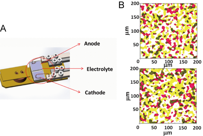
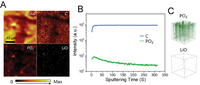
图19 (A) LPO@AB/S 样品在Cs+ 连续溅射120 s后的C-、PO3-和LiO-物种的TOF-SIMS 图像;(B) 通过溅射获得的C-和PO3-物种的深度剖面图;(C) 溅射体积的3D效果图

Fig.19 (A) TOF-SIMS images of C-, PO3-, and LiO- species after Cs+ consecutive sputtering for 120 s for the LPO@AB/S sample. (B) Depth profile of C- and PO3- species obtained by sputtering. (C) 3D render images of the sputtered volume of PO3- and LiO- species[17]. Copyright 2024, Wiley

It should be noted that TOF-SIMS typically requires a relatively long analysis time (>2 h) during depth profiling, especially for large-scale area analysis, and continuous ion sputtering may lead to unintended changes in the surface chemical state or structure of the cathode material. In light of this, developing multimodal cascade techniques to simultaneously obtain multidimensional information on composition, structure, and performance represents an important research direction for addressing the challenges of spatiotemporal resolution characterization in complex systems. Recently, work has integrated TOF-SIMS with SEM-based nanoindentation technology, enabling the simultaneous analysis of chemical composition changes and high-precision monitoring of mechanical properties to elucidate the chemo-mechanical behavior of composite electrodes[132].This innovative advancement provides valuable insights for the development of multi-technique integration, and it holds promise for future applications in experimental studies on the mechanical effects of cathodes in ASSLSBs.

5.3 Neutron-based technologies

In recent years, neutron-based characterization techniques such as neutron diffraction (ND) and neutron scattering have also been gradually applied to the study of cathodes in ASSLSBs. During the interaction between neutrons and atomic nuclei, the low energy of neutrons and their weak interaction with nuclei result in a high penetration depth, which is advantageous for probing the bulk regions of crystalline materials. Moreover, neutron diffraction differs from XRD in that it targets atomic nuclei rather than electrons, giving each technique a distinct focus and enabling them to provide complementary structural information. For example, Yu et al.[133]used neutron powder diffraction (NPD) in combination with XRD to demonstrate that the high ionic conductivity of Li6PS5Br arises from the high purity of lithium ions, the shortened average lithium-ion hopping distance, and the optimal arrangement of Br sites.
Neutron scattering is a powerful technique for obtaining structural information about materials, including small-angle neutron scattering (SANS) and quasi-elastic neutron scattering (QENS)[134-136].Currently, SANS is primarily used to study the distribution of sulfur in sulfur–carbon composites. The pore scattering effect of carbon's porous structure hinders the detection of sulfur, and traditional analytical tools struggle to detect this effect in mesoporous dispersed materials, making small-angle neutron scattering an ideal detection technique. Gungor et al.[137]used operando SANS to demonstrate that, during the first discharge cycle, a CEI forms inside the nanopores of nanoporous sulfur–carbon electrodes, not just on the outer surface of the particles. Chien et al.[135]employed SANS to elucidate the relationship between sulfur deposition on carbon nanotubes (CNTs) and battery performance. The study shows that at moderate discharge rates, a shortage of Li+ ions limits the utilization of active materials, directly constraining electrode reaction kinetics. More advanced scattering techniques include neutron pair distribution function (N-PDF) analysis. Similar to X-ray PDF analysis, it is typically used to study the local atomic structure of materials and is generally performed at synchrotron facilities. Garcia-Mendez et al.[138]investigated the local structure of sulfide SSEs prepared using different hot-pressing procedures. The study found a correlation between the local coordination of Li-S polyhedra and the elastic constants.
The principle of neutron imaging is similar to that of X-ray imaging; however, compared with X-ray imaging, neutron imaging offers a key advantage in lithium battery systems: neutrons have a strong interaction with lithium atoms. As a result, neutron imaging has the potential to become an important characterization technique for observing deeply embedded lithium-ion transport processes. However, its application in ASSLSBs remains limited by relatively low spatial resolution (typically only tens of micrometers)[139].To address this issue, several measures have been taken. First, samples suitable for neutron imaging typically consist of thick electrodes, and the characterization images require special processing. For example, lithium distribution images obtained using two-dimensional radiography are converted into neutron attenuation levels to indirectly represent lithium transport. Moreover, although the lithium environment between the SSE and the sulfur cathode is similar at the beginning of discharge, which affects neutron imaging at the interface, the additional carbon and sulfur present in the cathode are sufficient to alter the density of lithium distribution, thereby enabling differentiation of these two regions in radiographic images. This technique is currently used to reveal the kinetic processes in sulfur-based cathodes. Bradbury et al.[140]employed operandoneutron radiography and neutron tomography to observe the distribution of lithium within the composite sulfur cathode during cycling. Based on the rate of change in neutron attenuation as measured by neutron radiography, it was found that the reaction front moves from the separator side toward the current collector during initial discharge (Figure 20). Combined with three-dimensional neutron tomography, it was concluded that residual lithium elements concentrate near the current collector after charging, demonstrating that slow Li+transport within the cathode is the fundamental factor limiting the battery's rate performance.
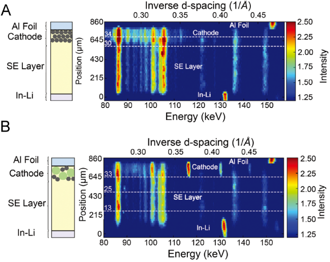
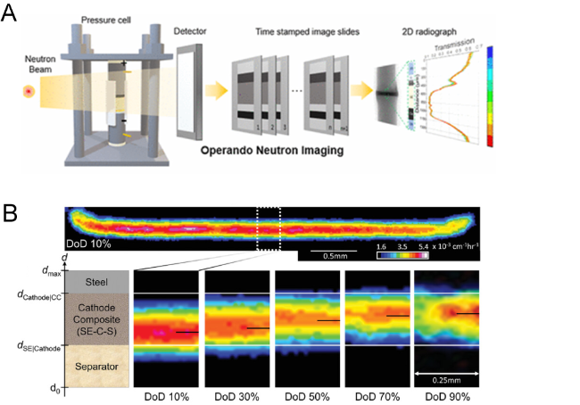
图20 (A) 中子成像示意图。(B) S/LPSC/C 固态复合材料阴极在不同电荷状态下的Operando中子成像。正极在不同电荷状态下的中子成像,并叠加了锂的浓度

Fig.20 (A) Diagram of an for neutron imaging[139]. (B) Operando neutron imaging of a S/LPSC/C solid-state composite cathode at different states of charge with the concentration of Li overlaid[140]. Copyright 2024, ACS, Copyright 2022, Wiley

5.4 X-ray computed tomography

XCT is a commonly used technique in medical imaging. Due to its non-destructive nature and its ability to acquire and image internal, buried features of materials or objects, XCT has also found widespread application in the electrochemical field[141-145]. The ability to generate high-resolution tomographic images non-destructively distinguishes XCT from other three-dimensional imaging techniques such as FIB and TOF-SIMS, which require ablation of material from the sample to produce tomographic images. The resolution of XCT imaging depends on the characteristics of the X-ray source, optical components, and experimental setup. In situ XCT with micrometer-level resolution can be performed on material sections extracted from batteries, while in situ experiments require battery casings that are very thin in thickness to ensure sufficient X-ray transmission[146].
In ASSLSB studies, in-situ synchrotron radiation XCT is more commonly used; as mentioned earlier, it is typically employed to observe the mechanical effects of sulfur-based cathodes[147-148].In addition, due to the high spatial resolution and favorable detection depth provided by its high-energy X-rays, XCT has recently made a series of advances in elucidating the kinetics of the Li2S nucleation process driven by catalytic mechanisms[149-150].For example, Song et al.[151] observed the spatial distribution of Li2S in synchrotron radiation XCT images and found that nitrogen vacancy defects in porous carbon serve as the active centers for the Li2S nucleation reaction. Moreover, the higher defect density in CA-2 promotes the kinetics of the Li2S nucleation reaction, demonstrating that graphene enhances electrocatalytic activity due to the presence of vacancies and tunable defect densities. In studies of copper-based catalyst systems, synchrotron X-ray 3D nanoCT also exhibits overwhelming functional advantages over other morphological characterization methods in detecting the Li2S nucleation reaction (Figure 21).It can be clearly observed that, due to the synergistic rapid catalysis of Cu-ETL-INT, the volume fraction of Li2S deposits is significantly higher than that achieved with other catalysts[152]. Although current nanoscale imaging resolutions are still insufficient to observe atomic-scale catalyst evolution, visualizing coordinated single atoms during the Li2S nucleation reaction is crucial for studying catalytic mechanisms.
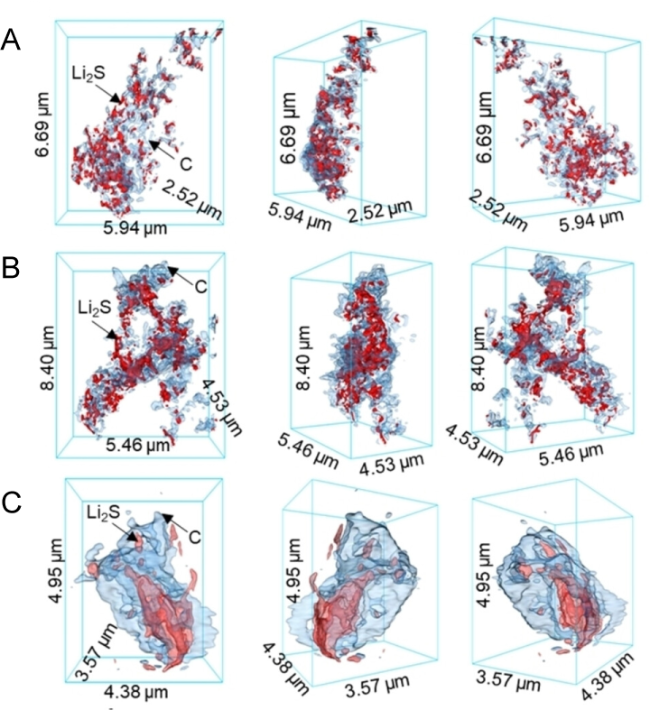
图21 同步辐射X射线三维纳米CT图像:碳基底上的Li2S沉淀与(A) Cu-ETL-INT、(B) Cu-ETL和(C) Cu-INT,其中红色、蓝色分别为Li2S和碳基底

Fig.21 Synchrotron radiation X-ray 3D nano-CT images of Li2S precipitations on carbon substrates with (A) Cu-ETL-INT, (B) Cu-ETL and (C) Cu-INT, where the red, blue is Li2S and carbon substrate, respectively[152]. Copyright 2025, Wiley

In addition, synchrotron radiation XCT scans have relatively short scan times, making them well-suited for combined characterization with spectroscopic techniques, including XANES-CT and PDF-CT[153-157].They have already been used in in-situ experiments to characterize the chemical composition of SSB materials, but have not yet been widely adopted in the field of sulfur-based cathodes for ASSLSBs.
More advanced characterization techniques, including magnetic resonance imaging (MRI), Rutherford backscattering spectroscopy (RBS), electron holography (EH), and atom probe tomography (APT), have demonstrated unique advantages in studying the interfacial chemistry and defect evolution in solid-state lithium batteries[158-161].However, the application of these techniques in elucidating the complex reaction kinetics and mechanical degradation of ASSLSBs is still in its early stages.

6 Conclusion and Outlook

Over the past several decades, significant progress has been made in developing and applying advanced in situ/ex situ characterization techniques for battery research. These technologies have opened new avenues for studying the structure, morphology, and chemical properties of cathode materials and components in ASSLSBs, as well as their relationship to electrochemical battery performance. Accordingly, this article reviews the latest advances in various characterization techniques—ranging from X-ray-, electron-, and optical-based methods to other emerging technologies—with a focus on ASSLSB cathodes. It emphasizes the role of these techniques in elucidating the mechanisms underlying slow cathode kinetics and mechanical degradation, thereby providing theoretical guidance for the design of high-performance cathodes.
By employing various in situ/non-in situ characterization techniques, phenomena such as phase transitions and volume expansion in active materials can be observed at the nanoscale or even atomic scale, providing crucial insights into the chemical, mechanical, and electrochemical transformations of cathode materials. However, extensive research indicates that sulfur-based cathodes typically undergo coordinated changes involving macroscopic mechanical transformations and microscopic compositional reorganization during the reaction process, with these phenomena often occurring on a millisecond timescale. This places high demands on the integration of multiple characterization techniques and on rapid characterization. Consequently, the future direction of characterization technology must involve the integrated consolidation of multiple techniques to simultaneously characterize the interactions among various substances within the electrode. As previously mentioned, a substantial body of work is currently dedicated to integrating various characterization techniques into a unified platform, with emerging new tools including AFM-Raman, AFM-IR, XRT-XANES, and others[162-164].From this perspective, battery systems compatible with multi-characterization can leverage artificial intelligence to assist in data analysis, enabling rapid analysis across smaller cascading time/space scales—and thereby directly yielding multi-scale, multi-parameter characterization data.
There are still some shortcomings and challenges in the field of characterization of the all-solid-state lithium-sulfur battery cathode described in this paper:
(1) The commercialization of all-solid-state lithium-sulfur batteries is still constrained by key challenges such as the slow interfacial kinetics of the sulfur cathode and mechanical degradation caused by volume changes. However, existing characterization techniques have yet to meet research needs in terms of precision and applicability, resulting in a lack of clear understanding of the interfacial behavior and electrochemical mechanisms of sulfur-based cathodes in ASSLSBs, which in turn hinders their development. Therefore, developing high-precision characterization instruments based on fourth-generation synchrotron radiation sources to reveal underlying electrochemical mechanisms holds promise for breaking through the core bottlenecks currently faced by ASSLSB cathodes.
(2) Sulfur-based materials pose significant challenges in characterization due to their low melting point and high compositional sensitivity. Although modification strategies such as carbon coating can partially mitigate these issues, the development of emerging non-destructive characterization techniques remains the fundamental solution. In addition to cryo-electron microscopy, small-angle scattering techniques based on X-rays and neutrons (SAXS, SANS) have recently shown significant potential in elucidating discharge products in liquid lithium-sulfur batteries and the reaction kinetics of lithium anodes[165-166].However, these emerging technologies are still in the developmental stage when applied to solid-state lithium-sulfur batteries, and there is an urgent need for multi-technique synergy to obtain comprehensive information. For instance, given the differences in detection ranges between neutron and X-ray small-angle scattering techniques, their combined use holds promise for monitoring the evolution of sulfur spatial distribution in solid-state systems.
(3) A significant gap still exists between the fundamental research on ASSLSB cathodes and their actual application performance parameters. This gap primarily stems from the fact that battery development and characterization are typically conducted under highly idealized laboratory conditions (such as inert atmospheres, controlled temperature and humidity, and high stacking pressure), making it difficult to effectively extrapolate theoretical models to real-world battery packs. Building an integrated multimodal in-situ characterization platform that simultaneously simulates complex factors such as dynamic changes in temperature and humidity under real operating conditions is an effective way to bridge the aforementioned knowledge gap. However, designing experimental setups that are compatible with multi-characterization technology terminals still presents significant technical challenges. A key difficulty lies in the fact that achieving these operational parameters often relies on large-scale precision instruments, which conflict with the inherent spatial, compatibility, or operational constraints of the terminal stations. Furthermore, current research generally lacks detailed reporting on specific experimental working parameters, which further hinders the standardized construction of such integrated platforms.
In summary, each of the aforementioned techniques has its own advantages and disadvantages. Although not all characterization techniques were discussed above, the valuable insights and information are generally applicable to the development of ASSLSB cathodes. We strongly recommend considering relevant technical benchmarks for sulfur-based cathodes to enable characterization under conditions as close to real-world scenarios as possible. By integrating various advanced characterization techniques and combining data-driven and physics-driven modeling approaches, it is expected that comprehensive evidence and robust support can be provided for the development of high-performance ASSLSBs.
[1]
Cano Z P, Banham D, Ye S Y, Hintennach A, Lu J, Fowler M, Chen Z W. Nat. Energy, 2018, 3(4): 279.

[2]
Etacheri V, Marom R, Elazari R, Salitra G, Aurbach D. Energy Environ. Sci., 2011, 4(9): 3243.

[3]
Yang X F, Luo J, Sun X L. Chem. Soc. Rev., 2020, 49(7): 2140.

[4]
Ding B, Wang J, Fan Z J, Chen S, Lin Q Y, Lu X J, Dou H, Kumar Nanjundan A, Yushin G, Zhang X G, Yamauchi Y. Mater. Today, 2020, 40: 114.

[5]
Lee J, Zhao C, Wang C H, Chen A N, Sun X L, Amine K, Xu G L. Chem. Soc. Rev., 2024, 53(10): 5264.

[6]
Liu Y, He P, Zhou H. Adv. Energy Mater., 2018, 8(4): 1701602.

[7]
Tripathi A M, Su W N, Hwang B J. Chem. Soc. Rev., 2018, 47(3): 736.

[8]
Morino Y, Sano H, Kawamoto K, Fukui K I, Takeuchi M, Sakuda A, Hayashi A. Solid State Ion., 2023, 392: 116162.

[9]
Raiß C, Peppler K, Janek J, Adelhelm P. Carbon, 2014, 79: 245.

[10]
Liu J, Qian T, Wang M F, Zhou J Q, Xu N, Yan C L. Nano Lett., 2018, 18(7): 4598.

[11]
Wang D W, Jhang L J, Kou R, Liao M, Zheng S Y, Jiang H, Shi P, Li G X, Meng K, Wang D H. Nat. Commun., 2023, 14: 1895.

[12]
Wu H L, Huff L A, Gewirth A A. ACS Appl. Mater. Interfaces, 2015, 7(3): 1709.

[13]
Wujcik K H, Pascal T A, Pemmaraju C D, Devaux D, Stolte W C, Balsara N P, Prendergast D. Adv. Energy Mater., 2015, 5(16): 1500285.

[14]
Bradbury R, Kardjilov N, Dewald G F, Tengattini A, Helfen L, Zeier W G, Manke I. Adv. Funct. Mater., 2023, 33(38): 2302619.

[15]
Song H, Münch K, Liu X, Shen K, Zhang R, Weintraut T, Yusim Y, Jiang D, Hong X, Meng J. Nature, 2025, 637 (8047): 846.

[16]
Song Y X, Wan J, Guo H J, Shi Y, Hu X C, Liu B, Yan H J, Wen R, Wan L J. Energy Storage Mater., 2021, 41: 642.

[17]
Zhong H Y, Su Y, Ma R Q, Luo Y, Lin H X, Gu J B, Gong Z L, Yang Y. Adv. Funct. Mater., 2024, 34(30): 2315925.

[18]
Gorlin Y, Patel M U M, Freiberg A, He Q, Piana M, Tromp M, Gasteiger H A. J. Electrochem. Soc., 2016, 163(6): A930.

[19]
Yu S H, Zachman M J, Kang K, Gao H, Huang X, DiSalvo F J, Park J, Kourkoutis L F, Abruña H D. Adv. Energy Mater., 2019, 9(47): 1902773.

[20]
Yu S H, Huang X, Schwarz K, Huang R, Arias T A, Brock J D, Abruña H D. Energy Environ. Sci., 2018, 11(1): 202.

[21]
Cheetham A K, Wilkinson A P. Angew. Chem. Int. Ed., 1992, 31(12): 1557.

[22]
Kunz M, Tamura N, Chen K, MacDowell A A, Celestre R S, Church M M, Fakra S, Domning E E, Glossinger J M, Kirschman J L. Rev. Sci. Instrum., 2009, 80(3): 035108.

[23]
Kamaya N, Homma K, Yamakawa Y, Hirayama M, Kanno R, Yonemura M, Kamiyama T, Kato Y, Hama S, Kawamoto K, Mitsui A. Nat. Mater., 2011, 10(9): 682.

[24]
Hosseini S M, Varzi A, Ito S, Aihara Y, Passerini S. Energy Storage Mater., 2020, 27: 61.

[25]
Pan W L, Yamamoto K, Matsunaga T, Watanabe T, Kumar M, Thakur N, Uchiyama T, Uesugi M, Takeuchi A, Sakuda A, Hayashi A, Tatsumisago M, Uchimoto Y. Batter. Supercaps, 2024, 7: e202300427.

[26]
Cook J B, Lin T C, Kim H S, Siordia A, Dunn B S, Tolbert S H. ACS Nano, 2019, 13(2): 1223.

[27]
El Kharbachi A, Wind J, Ruud A, Høgset A B, Nygård M M, Zhang J X, Sørby M H, Kim S, Cuevas F, Orimo S I, Fichtner M, Latroche M, Fjellvåg H, Hauback B C. Phys. Chem. Chem. Phys., 2020, 22(25): 13872.

[28]
Zhao W, Zhang Y, Liu Q S, Song Y J, Li X, Ren L P, Yin G P, Lou S F, Wang J J. Angew. Chem. Int. Ed., 2025, 64: e202413670.

[29]
Sun X, Stavola A M, Cao D X, Bruck A M, Wang Y, Zhang Y L, Luan P C, Gallaway J W, Zhu H L. Adv. Energy Mater., 2021, 11(3): 2002861.

[30]
Sun F, Dong K, Osenberg M, Hilger A, Risse S, Lu Y, Kamm P H, Klaus M, Markötter H, García-Moreno F, Arlt T, Manke I. J. Mater. Chem. A, 2018, 6(45): 22489.

[31]
Sun F, Osenberg M, Dong K, Zhou D, Hilger A, Jafta C J, Risse S, Lu Y, Markötter H, Manke I. ACS Energy Lett., 2018, 3(2): 356.

[32]
Ando T, Sato Y, Matsuyama T, Sakuda A, Tatsumisago M, Hayashi A. J. Ceram. Soc. Japan, 2020, 128(5): 233.

[33]
Xu Y H, Wen Y, Zhu Y J, Gaskell K, Cychosz K A, Eichhorn B, Xu K, Wang C S. Adv. Funct. Mater., 2015, 25(27): 4312.

[34]
Li M, Liu W W, Luo D, Chen Z W, Amine K, Lu J. ACS Energy Lett., 2022, 7(2): 577.

[35]
Ji X L, Lee K T, Nazar L F. Nat. Mater., 2009, 8(6): 500.

[36]
Luo L, Li J Y, Yaghoobnejad Asl H, Manthiram A. ACS Energy Lett., 2020, 5(4): 1177.

[37]
Yamaguchi H, Ishihara Y, Haniu Y, Sakuda A, Hayashi A, Kobayashi K, Hiroi S, Yamada H, Tseng J C, Shimono S, Ohara K. Commun. Chem., 2025, 8: 10.

[38]
Yang F P, Feng X F, Liu Y S, Kao L C, Glans P A, Yang W L, Guo J H. Energy Environ. Mater., 2021, 4(2): 139.

[39]
Li X, Yuan L X, Liu D Z, Xiang J W, Li Z, Huang Y H. Small, 2022, 18(43): 2106970.

[40]
Yan Y Y, Cheng C, Zhang L, Li Y G, Lu J. Adv. Energy Mater., 2019, 9(18): 1900148.

[41]
Zhao E Y, Nie K H, Yu X Q, Hu Y S, Wang F W, Xiao J, Li H, Huang X J. Adv. Funct. Mater., 2018, 28(38): 1707543.

[42]
Xiao Y, Yamamoto K, Matsui Y, Watanabe T, Sakuda A, Nakanishi K, Uchiyama T, Hayashi A, Shingubara S, Tatsumisago M, Ishikawa M, Watanabe M, Uchimoto Y. ACS Appl. Energy Mater., 2021, 4(1): 186.

[43]
Cao D X, Sun X, Li F, Bak S M, Ji T T, Geiwitz M, Burch K S, Du Y H, Yang G C, Zhu H L. Angew. Chem. Int. Ed., 2023, 62(20): e202302363.

[44]
Kim J T, Rao A, Nie H Y, Hu Y, Li W H, Zhao F P, Deng S X, Hao X G, Fu J M, Luo J, Duan H, Wang C H, Singh C V, Sun X L. Nat. Commun., 2023, 14: 6404.

[45]
Gao X, Zheng X L, Tsao Y, Zhang P, Xiao X, Ye Y S, Li J, Yang Y F, Xu R, Bao Z N, Cui Y. J. Am. Chem. Soc., 2021, 143(43): 18188.

[46]
Shen J D, Liang Z W, Gu T T, Sun Z Y, Wu Y W, Liu X Q, Liu J H, Zhang X Y, Liu J W, Shen L, Zhu M, Liu J. Energy Environ. Sci., 2024, 17(16): 6034.

[47]
Timoshenko J, Kuzmin A. Comput. Phys. Commun., 2009, 180(6): 920.

[48]
Cao G, Li X, Li M, Yang X, Duan R, Li M, Jiang Q, Li J, Wang J, Bai M. Adv. Funct. Mater., 2025, 2504228.

[49]
Pan H, Zhang M H, Cheng Z, Jiang H Y, Yang J G, Wang P F, He P, Zhou H S. Sci. Adv., 2022, 8(15): eabn4372.

[50]
Zhang Q, Huang N, Huang Z, Cai L T, Wu J H, Yao X Y. J. Energy Chem., 2020, 40: 151.

[51]
Liu R L, Wei Z Y, Peng L L, Zhang L Y, Zohar A, Schoeppner R, Wang P Q, Wan C Z, Zhu D, Liu H T, Wang Z Z, Tolbert S H, Dunn B, Huang Y, Sautet P, Duan X F. Nature, 2024, 626(7997): 98.

[52]
Ohno S, Rosenbach C, Dewald G F, Janek J, Zeier W G. Adv. Funct. Mater., 2021, 31(18): 2010620.

[53]
Rui X Y, Ren D S, Liu X, Wang X D, Wang K Y, Lu Y, Li L W, Wang P B, Zhu G L, Mao Y Q, Feng X N, Lu L G, Wang H W, Ouyang M G. Energy Environ. Sci., 2023, 16(8): 3552.

[54]
Khurram Tufail M, Ahmad N, Zhou L, Faheem M, Yang L, Chen R J, Yang W. Chem. Eng. J., 2021, 425: 130535.

[55]
Walther F, Randau S, Schneider Y, Sann J, Rohnke M, Richter F H, Zeier W G, Janek J. Chem. Mater., 2020, 32(14): 6123.

[56]
Wang S, Zhang Y B, Zhang X, Liu T, Lin Y H, Shen Y, Li L L, Nan C W. ACS Appl. Mater. Interfaces, 2018, 10(49): 42279.

[57]
Koerver R, Walther F, Aygün I, Sann J, Dietrich C, Zeier W G, Janek J. J. Mater. Chem. A, 2017, 5(43): 22750.

[58]
Wood K N, Steirer K X, Hafner S E, Ban C M, Santhanagopalan S, Lee S H, Teeter G. Nat. Commun., 2018, 9: 2490.

[59]
Wu X H, Villevieille C, Novák P, El Kazzi M. Phys. Chem. Chem. Phys., 2018, 20(16): 11123.

[60]
Narayanan S, Ulissi U, Gibson J S, Chart Y A, Weatherup R S, Pasta M. Nat. Commun., 2022, 13: 7237.

[61]
Aktekin B, Kataev E, Riegger L M, Garcia-Diez R, Chalkley Z, Becker J, Wilks R G, Henss A, Bär M, Janek J. ACS Energy Lett., 2024, 9(7): 3492.

[62]
Nandasiri M I, Camacho-Forero L E, Schwarz A M, Shutthanandan V, Thevuthasan S, Balbuena P B, Mueller K T, Murugesan V. Chem. Mater., 2017, 29(11): 4728.

[63]
Zhang L, Zhang X, Guo B, Rong Z, Yan Z, Wang B, Li M, Wang Z, Zhu L, Huang Q. ACS Energy Lett., 2025, 10: 898.

[64]
Zhang Y Y, Sun Y L, Peng L F, Yang J Q, Jia H H, Zhang Z R, Shan B, Xie J. Energy Storage Mater., 2019, 21: 287.

[65]
Ohno S, Koerver R, Dewald G, Rosenbach C, Titscher P, Steckermeier D, Kwade A, Janek J, Zeier W G. Chem. Mater., 2019, 31(8): 2930.

[66]
Oh Y S, Kim M, Kang S, Park J Y, Lim H T. Chem. Eng. J., 2022, 442: 136229.

[67]
Zou J, Zhao J, Wang B J, Chen S L, Chen P Y, Ran Q W, Li L, Wang X, Yao J M, Li H, Huang J Y, Niu X B, Wang L P. ACS Appl. Mater. Interfaces, 2020, 12(40): 44850.

[68]
Zhang Y W, Luo Y T, Fincher C, McProuty S, Swenson G, Banerjee S, Pharr M. Energy Storage Mater., 2019, 16: 491.

[69]
Baudry P, Armand M, Gauthier M, Masounave J. Solid State Ion., 1988, 28: 1567.

[70]
Marceau H, Kim C S, Paolella A, Ladouceur S, Lagacé M, Chaker M, Vijh A, Guerfi A, Julien C M, Mauger A, Armand M, Hovington P, Zaghib K. J. Power Sources, 2016, 319: 247.

[71]
Deng R M, Ke B Y, Xie Y H, Cheng S L, Zhang C C, Zhang H, Lu B G, Wang X H. Nano-Micro Lett., 2023, 15: 73.

[72]
Jin T W, Liang K Y, Yu J H, Wang T, Li Y H, Li T D, Ong S P, Yu J S, Yang Y. Nano Lett., 2024, 24(22): 6625.

[73]
Pervez S A, Vinayan B P, Ali Cambaz M, Melinte G, Diemant T, Braun T, Karkera G, Behm R J, Fichtner M. J. Mater. Chem. A, 2020, 8(32): 16451.

[74]
Zhou J, Holekevi Chandrappa M L, Tan S, Wang S, Wu C, Nguyen H, Wang C, Liu H, Yu S, Miller Q R. Nature, 2024, 627(8003): 301.

[75]
Perrenot P, Bayle-Guillemaud P, Jouneau P H, Boulineau A, Villevieille C. ACS Energy Lett., 2024, 9(8): 3835.

[76]
Shi T, Zhang Y Q, Tu Q S, Wang Y H, Scott M C, Ceder G. J. Mater. Chem. A, 2020, 8(34): 17399.

[77]
Choi S, Jeon M, Ahn J, Jung W D, Choi S M, Kim J S, Lim J, Jang Y J, Jung H G, Lee J H, Sang B I, Kim H. ACS Appl. Mater. Interfaces, 2018, 10(28): 23740.

[78]
Hlushkou D, Reising A E, Kaiser N, Spannenberger S, Schlabach S, Kato Y, Roling B, Tallarek U. J. Power Sources, 2018, 396: 363.

[79]
Kim H, Lee J T, Magasinski A, Zhao K J, Liu Y, Yushin G. Adv. Energy Mater., 2015, 5(24): 1501306.

[80]
Yang Z Z, Zhu Z Y, Ma J, Xiao D D, Kui X, Yao Y, Yu R C, Wei X, Gu L, Hu Y S, Li H, Zhang X X. Adv. Energy Mater., 2016, 6(20): 1600806.

[81]
Xu R, Belharouak I, Zhang X F, Chamoun R, Yu C, Ren Y, Nie A M, Shahbazian-Yassar R, Lu J, Li J C M, Amine K. ACS Appl. Mater. Interfaces, 2014, 6(24): 21938.

[82]
Gong Y, Chen Y Y, Zhang Q H, Meng F Q, Shi J A, Liu X Y, Liu X Z, Zhang J N, Wang H, Wang J Y, Yu Q, Zhang Z, Xu Q, Xiao R J, Hu Y S, Gu L, Li H, Huang X J, Chen L Q. Nat. Commun., 2018, 9: 3341.

[83]
Wang Z F, Tang Y F, Zhang L Q, Li M, Shan Z W, Huang J Y. Small, 2020, 16(28): 2001899.

[84]
Yu P W, Sun S R, Sun C H, Zeng C Y, Hua Z, Ahmad N, Shao R W, Yang W. Adv. Funct. Mater., 2024, 34(8): 2306939.

[85]
Liu N, Lu Z D, Zhao J, McDowell M T, Lee H W, Zhao W T, Cui Y. Nat. Nanotechnol., 2014, 9(3): 187.

[86]
Yang L T, Li X, Pei K, You W B, Liu X H, Xia H, Wang Y G, Che R C. Adv. Funct. Mater., 2021, 31(35): 2103971.

[87]
Tang W, Chen Z, Tian B, Lee H W, Zhao X, Fan X, Fan Y, Leng K, Peng C, Kim M H. J. Am. Chem. Soc., 2017, 139(29): 10133.

[88]
Xu Z L, Huang J Q, Chong W G, Qin X Y, Wang X Y, Zhou L M, Kim J K. Adv. Energy Mater., 2017, 7(9): 1602078.

[89]
Levin B D A, Zachman M J, Werner J G, Sahore R, Nguyen K X, Han Y M, Xie B Q, Ma L, Archer L A, Giannelis E P, Wiesner U, Kourkoutis L F, Muller D A. Microsc. Microanal., 2017, 23(1): 155.

[90]
Zachman M J, Tu Z Y, Archer L A, Kourkoutis L F. ACS Energy Lett., 2020, 5(4): 1224.

[91]
Choi H N, Kim H, Kim M J, Sun Y K. ACS Appl. Mater. Interfaces, 2024, 16(8): 11076.

[92]
Baddour-Hadjean R, Pereira-Ramos J P. Chem. Rev., 2010, 110(3): 1278.

[93]
Harks P P R M L, Mulder F M, Notten P H L. J. Power Sources, 2015, 288: 92.

[94]
Hagen M, Schiffels P, Hammer M, Dörfler S, Tübke J, Hoffmann M J, Althues H, Kaskel S. J. Electrochem. Soc., 2013, 160(8): A1205.

[95]
Chen B B, Xuan J, Offer G J, Wang H Z. Appl. Energy, 2020, 279: 115687.

[96]
Liu Y, Liu H W, Lin Y T, Zhao Y X, Yuan H, Su Y P, Zhang J F, Ren S Y, Fan H Y, Zhang Y G. Adv. Funct. Mater., 2021, 31(41): 2104863.

[97]
Song Y X, Shi Y, Wan J, Lang S Y, Hu X C, Yan H J, Liu B, Guo Y G, Wen R, Wan L J. Energy Environ. Sci., 2019, 12(8): 2496.

[98]
Chen J J, Yuan R M, Feng J M, Zhang Q, Huang J X, Fu G, Zheng M S, Ren B, Dong Q F. Chem. Mater., 2015, 27(6): 2048.

[99]
Meng X Y, Liu Y Z, Ma Y F, Boyjoo Y, Liu J, Qiu J S, Wang Z Y. Adv. Mater., 2023, 35(22): 2212039.

[100]
Wang S, Zhou J B, Feng S J, Patel M, Lu B Y, Li W K, Soulen C, Feng J Q, Meng Y S, Liu P. ACS Energy Lett., 2023, 8(6): 2699.

[101]
Wang Y, Wang G X, He P G, Hu J K, Jiang J H, Fan L Z. Chem. Eng. J., 2020, 393: 124705.

[102]
Li C, Zhang Q, Sheng J Z, Chen B, Gao R H, Piao Z H, Zhong X W, Han Z Y, Zhu Y F, Wang J L, Zhou G M, Cheng H M. Energy Environ. Sci., 2022, 15(10): 4289.

[103]
Otoyama M, Ito Y, Hayashi A, Tatsumisago M. J. Power Sources, 2016, 302: 419.

[104]
Yang G, Tao R M, Jafta C J, Shen C, Zhao S, He L L, Belharouak I, Nanda J. J. Phys. Chem. C, 2021, 125(24): 13146.

[105]
Lang S Y, Yu S H, Feng X R, Krumov M R, Abruña H D. Nat. Commun., 2022, 13: 4811.

[106]
McKelvy M L, Britt T R, Davis B L, Gillie J K, Lentz L A, Leugers A, Nyquist R A, Putzig C L. Anal. Chem., 1996, 68(12): 93.

[107]
Santos É A, Anchieta C G, Fernandes R C, Pinzón C M J, Miranda A N, Galantini I, Maia F C B, Doubek G, Rodella C B, Da Silva L M, Zanin H. Nano Energy, 2023, 116: 108809.

[108]
Santos É A, Policano M C, Pinzón M J, Galantini I, Gonçalves V A, Maia F C B, Macedo L J A, Doubek G, Freitas R G, Zanin H. J. Energy Chem., 2024, 98: 702.

[109]
Dillard C, Singh A, Kalra V. J. Phys. Chem. C, 2018, 122(32): 18195.

[110]
Saqib N, Ohlhausen G M, Porter J M. J. Power Sources, 2017, 364: 266.

[111]
Zhang W, Zhang Y Y, Peng L F, Li S P, Wang X M, Cheng S J, Xie J. Nano Energy, 2020, 76: 105083.

[112]
Shi C M, Alexander G V, O’Neill J, Duncan K, Godbey G, Wachsman E D. ACS Energy Lett., 2023, 8(4): 1803.

[113]
Yang J, Chu Y, Zhang X Z, Li Y X, Cui X M, Pan Q M. J. Energy Storage, 2024, 96: 112539.

[114]
Duan H H, Li L S, Fu X X, Deng Y F, Chen G H. Chem. Eng. J., 2022, 450: 138208.

[115]
Li S Y, Ruan J F, Jiang R H, Wu W, Liu M, Cao R G, Fang F, Sun D L, Song Y, Wang F. Energy Storage Mater., 2022, 48: 283.

[116]
Danis L, Gateman S M, Kuss C, Schougaard S B, Mauzeroll J. ChemElectroChem, 2017, 4(1): 6.

[117]
Liu X R, Wang D, Wan L J. Sci. Bull., 2015, 60(9): 839.

[118]
Tennyson E M, Gong C, Leite M S. ACS Energy Lett., 2017, 2(12): 2761.

[119]
Wan J, Hao Y, Shi Y, Song Y X, Yan H J, Zheng J, Wen R, Wan L J. Nat. Commun., 2019, 10: 3265.

[120]
Shi C M, Yu M P. Energy Storage Mater., 2023, 57: 429.

[121]
Ma R Q, Fan Y T, Jin Y T, Pan S Y, Zhong H Y, Luo Y, Gu J B, Luo M Z, Wu Y Q, Hu W X, Chen P Z, Su Y, Wu G Y, Yan J W, Gao J, Gong Z L, Yang Y. Adv. Energy Mater., 2024, 14(19): 2304412.

[122]
Sakai H, Taniguchi Y, Uosaki K, Masuda T. J. Power Sources, 2019, 413: 29.

[123]
Wang W W, Gu Y, Wang J H, Chen Z B, Yin X T, Wu Q H, Yan J W, Mao B W. J. Electrochem. Soc., 2022, 169(2): 020563.

[124]
Li M, Chen H, Guo C, Qian S S, Li H P, Wu Z Z, Xing C, Xue P, Zhang S Q. Adv. Energy Mater., 2023, 13(25): 2300646.

[125]
Mahankali K, Thangavel N K, Reddy Arava L M. Nano Lett., 2019, 19(8): 5229.

[126]
Oh J, Park G, Kim H, Kim S, Shin D O, Kim K M, Byon H R, Lee Y G, Hong S. ACS Appl. Mater. Interfaces, 2023, 15(22): 26660.

[127]
Zhu J, Lu L, Zeng K Y. ACS Nano, 2013, 7(2): 1666.

[128]
Liu G X, Tian J X, Wan J, Li Y, Shen Z Z, Chen W P, Zhao Y, Wang F Y, Liu B, Xin S, Guo Y G, Wen R. Angew. Chem. Int. Ed., 2022, 61(52): e202212744.

[129]
Song Y X, Shi Y, Wan J, Liu B, Wan L J, Wen R. Adv. Energy Mater., 2020, 10(25): 2000465.

[130]
Hu L Y, Yang T Q, Yan X, Liu Y N, Zhang W K, Zhang J, Xia Y, Wang Y, Gan Y P, He X P, Xia X H, Fang R Y, Tao X Y, Huang H. ACS Nano, 2024, 18(11): 8463.

[131]
Yamamoto M, Goto S, Tang R, Nomura K, Hayasaka Y, Yoshioka Y, Ito M, Morooka M, Nishihara H, Kyotani T. ACS Appl. Mater. Interfaces, 2021, 13(32): 38613.

[132]
Ai Q, Chen Z Y, Zhang B Y, Wang F, Zhai T S, Liu Y F, Zhu Y F, Terlier T, Fang Q Y, Liang Y L, Zhao L H, Wu C S, Guo H, Fan Z, Tang M, Yao Y, Lou J. ACS Energy Lett., 2023, 8(2): 1107.

[133]
Yu C, Hageman J, Ganapathy S, van Eijck L, Zhang L, Adair K R, Sun X L, Wagemaker M. J. Mater. Chem. A, 2019, 7(17): 10412.

[134]
Altorfer F, Buhrer W, Anderson I, Scharpf O, Bill H, Carron P L. J. Phys. Condens. Matter, 1994, 6(46): 9937.

[135]
Chien Y C, Lacey M J, Steinke N J, Brandell D, Rennie A R. Chem, 2022, 8(5): 1476.

[136]
Lefevr J, Cervini L, Griffin J M, Blanchard D. J. Phys. Chem. C, 2018, 122(27): 15264.

[137]
Senol Gungor A, von Mentlen J M, Ruthes J G A, García-Soriano F J, Drvarič Talian S, Presser V, Porcar L, Vizintin A, Wood V, Prehal C. ACS Appl. Mater. Interfaces, 2024, 16(49): 67651.

[138]
Garcia-Mendez R, Smith J G, Neuefeind J C, Siegel D J, Sakamoto J. Adv. Energy Mater., 2020, 10(19): 2000335.

[139]
Cao D X, Zhang Y X, Ji T T, Zhao X H, Cakmak E, Ozcan S, Geiwitz M, Bilheux J, Xu K, Wang Y, Burch K S, Tu Q H, Zhu H L. Nano Lett., 2024, 24(5): 1544.

[140]
Bradbury R, Dewald G F, Kraft M A, Arlt T, Kardjilov N, Janek J, Manke I, Zeier W G, Ohno S. Adv. Energy Mater., 2023, 13(17): 2203426.

[141]
Lu X K, Bertei A, Finegan D P, Tan C, Daemi S R, Weaving J S, O’Regan K B, Heenan T M M, Hinds G, Kendrick E, Brett D J L, Shearing P R. Nat. Commun., 2020, 11: 2079.

[142]
Ning Z Y, Jolly D S, Li G C, De Meyere R, Pu S D, Chen Y, Kasemchainan J, Ihli J, Gong C, Liu B Y, Melvin D L R, Bonnin A, Magdysyuk O, Adamson P, Hartley G O, Monroe C W, Marrow T J, Bruce P G. Nat. Mater., 2021, 20(8): 1121.

[143]
Pietsch P, Wood V. Annu. Rev. Mater. Res., 2017, 47: 451.

[144]
Scharf J, Chouchane M, Finegan D P, Lu B Y, Redquest C, Kim M C, Yao W L, Franco A A, Gostovic D, Liu Z, Riccio M, Zelenka F, Doux J M, Meng Y S. Nat. Nanotechnol., 2022, 17(5): 446.

[145]
Withers P J, Bouman C, Carmignato S, Cnudde V, Grimaldi D, Hagen C K, Maire E, Manley M, Du Plessis A, Stock S R. Nat. Rev. Meth. Primers, 2021, 1: 18.

[146]
Lewis J A, Cortes F J Q, Liu Y, Miers J C, Verma A, Vishnugopi B S, Tippens J, Prakash D, Marchese T S, Han S Y, Lee C, Shetty P P, Lee H W, Shevchenko P, De Carlo F, Saldana C, Mukherjee P P, McDowell M T. Nat. Mater., 2021, 20(4): 503.

[147]
Xu R Y, Xiang J W, Feng J R, Lu X K, Hao Z X, Kang L Q, Li M, Wu Y S, Tan C, Liu Y Y, He G J, Brett D J L, Shearing P R, Yuan L X, Huang Y H, Wang F R. Energy Storage Mater., 2020, 31: 164.

[148]
Zhang Z G, Dong K, Mazzio K A, Hilger A, Markötter H, Wilde F, Heinemann T, Manke I, Adelhelm P. Adv. Energy Mater., 2023, 13(2): 2203143.

[149]
Chen L, Sun Y J, Wei X J, Song L X, Tao G, Cao X, Wang D, Zhou G M, Song Y Z. Adv. Mater., 2023, 35(26): 2300771.

[150]
Yu S L, Sun Y J, Song L X, Cao X, Chen L, An X T, Liu X H, Cai W L, Yao T, Song Y Z, Zhang W. Nano Energy, 2021, 89: 106414.

[151]
Chen L, Yu S L, Zhang Y P, Song Y Z, Song L X. J. Power Sources, 2021, 514: 230607.

[152]
Yang Q, Wang C S, Song L X, Zhang Y F, Shen Z Y, Cai W L, Song Y Z. Angew. Chem. Int. Ed., 2025, 64(3): e202415078.

[153]
Amezawa K, Kimura Y. Next Generation Batteries: Realization of High Energy Density Rechargeable Batteries. Singapore: Springer, 2021. 239.

[154]
Huang S, Kimura Y, Nakamura T, Ishiguro N, Sekizawa O, Nitta K, Uruga T, Takeuchi T, Okumura T, Tada M, Uchimoto Y, Amezawa K. J. Phys. Chem. C, 2024, 128(15): 6213.

[155]
Kimura Y, Fakkao M, Nakamura T, Okumura T, Ishiguro N, Sekizawa O, Nitta K, Uruga T, Tada M, Uchimoto Y, Amezawa K. ACS Appl. Energy Mater., 2020, 3(8): 7782.

[156]
Kimura Y, Huang S, Nakamura T, Ishiguro N, Sekizawa O, Nitta K, Uruga T, Takeuchi T, Okumura T, Tada M, Uchimoto Y, Amezawa K. Small Meth., 2023, 7(10): 2300310.

[157]
Wragg D S, Skautvedt C, Brennhagen A, Geiß C, Checchia S, Koposov A Y. J. Phys. Chem. C, 2023, 127(48): 23149.

[158]
Bazak J D, Allen J P, Krachkovskiy S A, Goward G R. J. Electrochem. Soc., 2020, 167(14): 140518.

[159]
Chandrashekar S, Trease N M, Chang H J, Du L S, Grey C P, Jerschow A. Nat. Mater., 2012, 11(4): 311.

[160]
Liang J W, Li X N, Zhao Y, Goncharova L V, Li W H, Adair K R, Banis M N, Hu Y F, Sham T K, Huang H, Zhang L, Zhao S Q, Lu S G, Li R Y, Sun X L. Adv. Energy Mater., 2019, 9(38): 1902125.

[161]
Xu X, Liu Y Z, Wang J, Isheim D, Dravid V P, Phatak C, Haile S M. Nat. Mater., 2020, 19(8): 887.

[162]
Conder J, Marino C, Novák P, Villevieille C. J. Mater. Chem. A, 2018, 6(8): 3304.

[163]
Dazzi A, Prater C B. Chem. Rev., 2017, 117(7): 5146.

[164]
Cosas Fernandes J P, Mareau V H, Gonon L. Int. J. Polym. Anal. Charact., 2018, 23(2): 113.

[165]
Prehal C, von Mentlen J M, Drvarič Talian S, Vizintin A, Dominko R, Amenitsch H, Porcar L, Freunberger S A, Wood V. Nat. Commun., 2022, 13: 6326.

[166]
Yang Q, Cai J Y, Li G W, Gao R H, Han Z Y, Han J J, Liu D, Song L X, Shi Z X, Wang D, Wang G M, Zheng W T, Zhou G M, Song Y Z. Nat. Commun., 2024, 15: 3231.

Outlines

/