Home Journals Progress in Chemistry
Progress in Chemistry

Abbreviation (ISO4): Prog Chem      Editor in chief: Jincai ZHAO

About  /  Aim & scope  /  Editorial board  /  Indexed  /  Contact  / 
Review

Hydrogen Production via Seawater Electrolysis: Current Advances and Future Perspectives on Process Optimization and System Integration

  • Dongyi Liu 1 ,
  • Miaoting Sun 1 ,
  • Yang Yu 1 ,
  • Jiaxiang Chen 1 ,
  • Yanting Zhou 1 ,
  • Xingxing Wang 2 ,
  • Wei Zhou , 1, *
Expand
  • 1 School of Energy Science and Engineering, Harbin Institute of Technology, Harbin 150001, China
  • 2 CHN ENERGY Yuedian Taishan Power Generation Co., Ltd., Taishan 529200, China

Received date: 2025-05-22

  Revised date: 2025-07-04

  Online published: 2025-12-10

Supported by

Key Research and Development Program of Heilongjiang Province(2024ZXJ03C06)

Natural Science Foundation of Heilongjiang Province(YQ2022E027)

National Natural Science Foundation of China(52476192)

Abstract

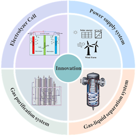
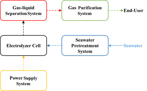
As a clean and efficient secondary energy source, hydrogen energy represents a strategic pillar for future energy transition, capable of replacing fossil fuels to achieve deep decarbonization in industries, transportation, and other sectors. In recent years, seawater electrolysis has emerged as a promising route for green hydrogen production, owing to its potential to utilize seawater as a feedstock and address offshore wind power utilization challenges in remote marine areas. However, current research on seawater electrolysis predominantly focuses on catalyst development at the material level, with insufficient attention to synergistic optimization at the system and process levels. To bridge this gap, this review systematically summarizes the state-of-the-art technologies and future trends in seawater electrolysis systems and processes. The system is decomposed into four key components: electrolyzer, power supply system, gas-liquid separation system, and gas purification system, with a comprehensive analysis of their current research progress. Additionally, this paper highlights innovations in non-catalyst aspects, including technological and methodological advancements. Finally, future directions and application prospects for seawater electrolysis systems are discussed, emphasizing the importance of integrated system design, scalability, and cost-effectiveness to accelerate industrial deployment. This work aims to provide insights into the holistic development of seawater electrolysis technology for sustainable hydrogen production.

Contents

1 Introduction

2 Principles, types of technologies and challenges of hydrogen production by electrolysis of water and seawater

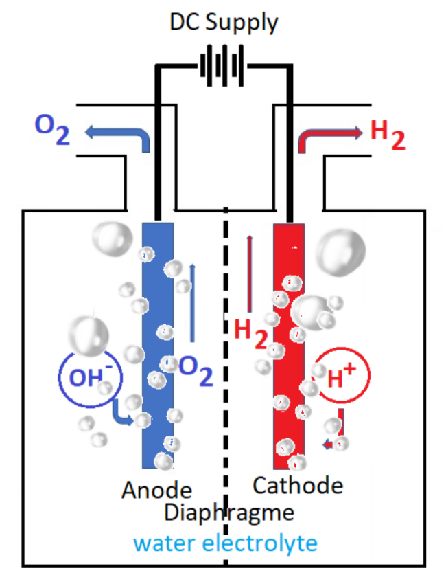
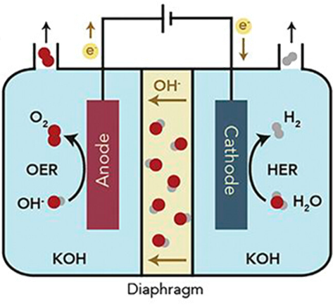
2.1 Hydrogen production by water electrolysis

2.2 Hydrogen production by sea water electrolysis

3 Hydrogen production system and process by seawater electrolysis

3.1 Seawater pretreatment system

3.2 Electrolyzer cell

3.3 Power supply system

3.4 Gas-liquid separation system

3.5 Gas purification system

4 Innovation in the process of hydrogen production by seawater electrolysis

4.1 Innovation of the electrolyzer

4.2 Innovation in water electrolysis method

5 Conclusions and prospects

Cite this article

Dongyi Liu , Miaoting Sun , Yang Yu , Jiaxiang Chen , Yanting Zhou , Xingxing Wang , Wei Zhou . Hydrogen Production via Seawater Electrolysis: Current Advances and Future Perspectives on Process Optimization and System Integration[J]. Progress in Chemistry, 2025 , 37(12) : 1877 -1901 . DOI: 10.7536/PC20250519

1 Introduction

Against the backdrop of global climate change and China's low-carbon energy transition, the development and utilization of clean energy has become increasingly important. As a clean, efficient, and renewable secondary energy source, hydrogen energy has emerged as a core focus of national energy strategies. Hydrogen energy boasts enormous application potential, with its use cases spanning transportation, industry, power generation, and the building sector, particularly in hard-to-decarbonize industries such as steel and chemicals[1].According to a report by the International Energy Agency (IEA), hydrogen has the potential to meet 20% of global energy demand by 2030 and reduce carbon dioxide emissions by 7 billion tons by 2050. However, approximately 95% of the world's current hydrogen production still relies on fossil fuel reforming (such as steam methane reforming) or coal gasification technologies, whose high carbon emissions run counter to the "dual carbon" goals. Therefore, achieving large-scale, low-cost production of green hydrogen—produced via electrolysis of water using renewable energy—has become a critical breakthrough for the development of the hydrogen energy industry.
Among the many hydrogen production methods, water electrolysis technology, particularly seawater electrolysis (i.e., producing hydrogen and oxygen by electrolyzing seawater), stands out due to its unique advantages such as "zero carbon emissions, wide availability of feedstock, and flexible compatibility with renewable energy sources"[2]. Compared with traditional fossil fuel-based hydrogen production, the core advantage of water electrolysis lies in its ability to flexibly match the fluctuating power output of wind, solar, and other renewable energy sources, thereby providing an effective pathway for large-scale integration and cross-temporal regulation of renewable energy[3]; at the same time, the hydrogen production process generates almost no greenhouse gases, and the full lifecycle carbon emission intensity can be reduced by more than 70%[4]; moreover, the produced hydrogen boasts a purity as high as 99.99%, making it directly suitable for applications such as fuel cells[5]. Currently, the mainstream technological routes for water electrolysis include alkaline water electrolysis (AWE), proton exchange membrane electrolysis (PEM), anion exchange membrane electrolysis (AEM)[6], and solid oxide electrolysis (SOEC)[7]. However, regardless of the technology employed, the overall performance and cost of the electrolysis system remain the key constraints limiting its large-scale deployment.
In summary, current research on water electrolysis for hydrogen production mainly focuses on optimizing and innovating single components such as catalyst materials. However, issues at the system level—such as energy transfer losses and dynamic response coordination among different units—still pose bottlenecks to large-scale applications. Therefore, the industrialization of water electrolysis technology not only depends on breakthroughs in catalyst performance but also requires deep coupling between process optimization and system-level coordination. From a system perspective, a water electrolysis hydrogen production device consists of four core units: the electrolyzer, the power supply system, the gas-liquid separation system, and the gas purification system. This article summarizes the research progress on the aforementioned water electrolysis hydrogen production systems. Figure 1shows the process flow diagram of a seawater electrolysis hydrogen production system.
图1 电解海水制氢系统工艺流程图

Fig.1 Process flow for seawater electrolysis hydrogen production system

2 The principles, technological types, and challenges of hydrogen production via water electrolysis and seawater electrolysis.

2.1 Electrolysis of Water for Hydrogen Production

2.1.1 Principle of Hydrogen Production via Water Electrolysis

In short, the predictive ability of existing scoring systems for bleeding events is limited, and their results are inconsistent[25,30,33].
图2 电解水制氢反应过程图[10]

Fig. 2 Diagram of the reaction process of hydrogen production by electrolysis of water[10]

(1) Reaction process of water splitting: The overall reaction in the electrolyzer is the decomposition of liquid water into hydrogen and oxygen. Although the electrode reactions appear different, they are essentially the same, particularly the discharge of H+and OH-ions:
$\mathrm{H}_{2} \mathrm{O} \rightarrow \mathrm{H}_{2}+\frac{1}{2} \mathrm{O}_{2}$
$\Delta E^{0}=E_{\mathrm{H}_{2} \mathrm{O} / \mathrm{H}_{2}}^{0}-E_{\mathrm{OH}^{-} / \mathrm{O}_{2}}^{0}=-1.23 \mathrm{~V}$
however, water splitting is not a spontaneous reaction at room temperature, so external energy input is required for this reaction to occur:
$\mathrm{H}_{2} \mathrm{O}(\mathrm{l}) \xrightarrow{\text { 电能 }} \mathrm{H}_{2}(\mathrm{~g})+\frac{1}{2} \mathrm{O}_{2}(\mathrm{~g})$
in an alkaline environment, the anode and cathode undergo the following reactions at their respective potentials:
$ \begin{aligned} \text { 阳极: } 2 \mathrm{OH}^{-} & \rightarrow \frac{1}{2} \mathrm{O}_{2}+\mathrm{H}_{2} \mathrm{O}+2 \mathrm{e}^{-} \\ E_{\mathrm{OH}^{-} / \mathrm{O}_{2}}^{0} & =0.4 \mathrm{~V} / \mathrm{RHE} \end{aligned}$
$\begin{array}{c} \text { 阴极: } 2 \mathrm{H}_{2} \mathrm{O}+2 \mathrm{e}^{-} \rightarrow \mathrm{H}_{2}+2 \mathrm{OH}^{-} \\ E_{\mathrm{H}_{2} \mathrm{O} / \mathrm{H}_{2}}^{0}=-0.83 \mathrm{~V} / \mathrm{RHE} \end{array}$
in an acidic environment, the anode and cathode undergo the following reactions at their respective potentials:
$\begin{array}{c} \text { 阳极: } \mathrm{H}_{2} \mathrm{O} \rightarrow \frac{1}{2} \mathrm{O}_{2}+2 \mathrm{H}^{+}+2 \mathrm{e}^{-} \\ E_{\mathrm{H}_{2} \mathrm{O} / \mathrm{O}_{2}}^{0}+1.23 \mathrm{~V} / \mathrm{RHE} \end{array}$
$ \begin{array}{l} \text { 阴极: } 2 \mathrm{H}^{+}+2 \mathrm{e}^{-} \rightarrow \mathrm{H}_{2} \\ \quad\quad E_{\mathrm{H}^{+} / \mathrm{H}_{2}}^{0}=0.00 \mathrm{~V} / \mathrm{RHE} \end{array}$
(2) The theoretical voltage for water splitting leads to the same conclusion when thermodynamic calculations of the water-splitting voltage are performed using the Gibbs-Helmholtz equation. At 25 ℃, the standard enthalpy of formation of gaseous water is ΔH 0= 57.8 kcal/mol. Since liquid water splits at the electrode, under standard conditions (25 ℃ and 1 standard atmosphere), the heat of vaporization of liquid water Q vmust also be considered:
$\begin{aligned} -\Delta H & =\Delta H^{0}+Q_{\mathrm{v}}=57.8+10.52 \\ & =68.32 \mathrm{kcal} / \mathrm{mol} \end{aligned}$
the change in free enthalpy (Gibbs energy) ΔG in an electrochemical processis given by the difference between the enthalpy change of the chemical reaction and the product of the standard temperature (25 ℃ = 298 K) and the entropy change ΔS.Gibbs energy is also equal to the product of the number of electrons exchanged in the electrochemical process z,the Faraday constant (F), and the potential difference ΔE between the anode and cathode:
$\Delta G=\Delta H-T \cdot \Delta S=-z \cdot F \cdot \Delta E$
from this equation, extract ΔEand calculate the theoretical voltage difference between the anode and cathode required for water splitting, also known as the water-splitting voltage:
$\Delta E=\frac{-\Delta H+T \cdot \Delta S}{z \cdot F}=1.23 \mathrm{~V}$
based on the reversible potentials of oxygen (obtained through oxidation) and hydrogen (obtained through reduction), ΔE is calculated,yielding the same theoretical voltage for water decomposition in either alkaline or acidic media:
$\begin{aligned} \Delta E_{\text {theoretical }} & =E_{\mathrm{ox}}-E_{\mathrm{red}}=E_{\mathrm{oxygen}}-E_{\mathrm{hydrogen}} \\ & =0.4-(-0.83)=1.23 \mathrm{~V} \end{aligned}$
$\begin{aligned} \Delta E_{\text {theoretical }} & =E_{\mathrm{ox}}-E_{\mathrm{red}}=E_{\mathrm{oxygen}}-E_{\mathrm{hydrogen}} \\ & =1.23-(0.00)=1.23 \mathrm{~V} \end{aligned}$
(3) Due to anode and cathode polarization (η) and the presence of the electrolyzer and RI(voltage drops across the electrolyte solution, conductors, contacts, and membrane), the actual voltage for water splitting is higher than the equilibrium voltage:
$\Delta E=\Delta E_{\text {theoretical }}+\eta_{\mathrm{a}}+\eta_{\mathrm{c}}+R \cdot I$
the type of electrode, the nature of the electrolyte, the electrochemical mechanisms of the electrochemical reactions, and the temperature all affect electrode polarization and determine overvoltage (the deviation from the standard equilibrium potential). Polarization consists of two components: one associated with electron transfer, known as charge-transfer polarization; the other related to mass transport, known as concentration polarization. The discharge overvoltage of hydrogen and oxygen has a significant impact on the voltage balance, so research aims to minimize overvoltage as much as possible. The voltage drops across the membrane, conductors, contacts, and electrolyte solution add up to a substantial voltage drop across the electrolyzer. At the same time, the type, concentration, and temperature of the electrolyte, as well as the bubbles produced, all influence the voltage drop across the electrolyte. Therefore, the actual water-splitting voltage ranges between 1.6 and 1.74 V, with the exact value depending on the type of electrolyte[11]..

2.1.2 Challenges and Research Status of Electrolysis for Hydrogen Production

Currently, there are four main types of water electrolysis technologies for hydrogen production: alkaline water electrolysis (AWE), proton exchange membrane electrolysis (PEM), anion exchange membrane electrolysis (AEM), and solid oxide electrolysis (SOEC).
(1) AWE hydrogen production technology: AWE hydrogen production technology is one of the most mature and widely applied methods, and has already been fully industrialized both domestically and internationally. The electrolyzer structure is shown in Figure 3. Its operating principle involves the reduction of water molecules at the cathode under the influence of direct current, producing hydrogen ions and hydroxide ions. Under the driving force of the electric field and the concentration gradient between the cathode and anode, these hydroxide ions migrate through the membrane to the anode, where an oxygen evolution reaction occurs, generating oxygen and water. In AWE electrolyzers, the electrolyte typically consists of a 30% (by mass) KOH solution, with an operating temperature range of 70–90 ℃. Membrane materials may include asbestos or polyphenylene sulfide, and the anode and cathode catalysts are generally nickel-plated perforated stainless steel[12].
图3 AWE电解水制氢技术原理图[13]

Fig.3 AWE water electrolysis technology for hydrogen production[13]

AWE technology is known for its simplicity, maturity, and reliability, and operates effectively under ambient temperature and pressure conditions. However, it also has certain drawbacks, including long start-up and shutdown response times, low current density, corrosiveness of the electrolyte, alkali permeation, environmental pollution concerns, and the need for complex maintenance of alkaline fluids. Demnitz et al.[14]studied the effect of adding iron to the electrolyte on improving electrolysis efficiency. The experimental results indicate that a moderate addition of iron can significantly enhance the efficiency of alkaline water electrolysis; however, during electrolysis, iron may deposit on the electrode surface or redissolve into the electrolyte, and its long-term effects require further investigation. Zhu et al.[15]conducted research on the impact of temperature on enhancing the efficiency of alkaline water electrolysis, proposing an asymmetric temperature control strategy in which the hydrogen evolution reaction and the oxygen evolution reaction proceed at different temperatures during electrolysis. The results show that asymmetric temperature control can significantly improve the efficiency of alkaline water electrolysis. Regarding the issue of pressurization in alkaline water electrolyzers, Brauns et al.[16]developed a dynamic process model comprising four sub-models to describe the system behavior in pressurized alkaline water electrolyzer systems with respect to gas contamination, electrolyte concentration, cell potential, and temperature. The results indicate that appropriate operating strategies and system design can effectively reduce gas contamination, optimize electrolyte circulation, and enhance the overall energy efficiency of the system.
(2) PEM hydrogen production technology: PEM (proton exchange membrane) hydrogen production technology is a method that generates hydrogen and oxygen by electrolyzing water molecules. This technology uses a specialized proton exchange membrane as the electrolyte, which effectively dissociates water molecules into hydrogen and oxygen. PEM electrolysis boasts high conversion efficiency, enabling more effective conversion of electrical energy into chemical energy in the form of high-purity hydrogen. Compared with traditional alkaline water electrolysis, PEM electrolysis operates at lower temperatures, reducing energy loss. In addition, PEM systems can respond rapidly to load changes, making them highly suitable for integration with intermittent renewable energy sources such as wind and solar power, thereby enhancing overall energy efficiency.
A PEM electrolyzer is a device used to electrolyze water to produce hydrogen, employing a special proton exchange membrane as the electrolyte, as shown in Figure 4.At the core of the electrolyzer is a thin membrane that selectively allows protons (hydrogen ions) to pass while blocking electrons. This creates a voltage difference between the electrodes, facilitating the dissociation of water molecules into hydrogen and oxygen. During electrolysis, water molecules are oxidized at the anode, producing oxygen, protons, and electrons. The protons migrate through the proton exchange membrane to the cathode, where they combine with electrons via a reduction reaction to form hydrogen gas.
图4 PEM电解水制氢技术原理图[17]

Fig.4 PEM water electrolysis technology for hydrogen production[17]

With the growing global demand for clean energy, PEM water electrolysis for hydrogen production is widely recognized as a promising hydrogen-generation method due to its high efficiency and environmental friendliness. Höglinger et al.[18]proposed a systematic testing method for PEM stacks, which, by comparing test results from different stacks, provides valuable insights into assessing design, material suitability, and operational performance, thereby advancing the development and application of proton exchange membrane water electrolysis technology. Padgett et al.[19]investigated two different structures of anode catalyst layers: an IrO2nanoparticle catalyst layer and a dispersed nanostructured thin film (NSTF) Ir catalyst layer. The study found that high electronic resistance leads to increased local overpotential in the catalyst layer, triggering non-uniform catalyst degradation. Zhang et al.[20]studied a novel sulfur-doped polysulfide (marcasite)-type electrocatalyst to enhance the catalyst's hydrogen evolution performance and stability in acidic media. Non-precious-metal-based hydrogen evolution catalysts reduce costs.
(3) AEM hydrogen production technology: AEM (anion exchange membrane) hydrogen production technology is one of the more advanced water electrolysis technologies currently in the early stages of research. The structure of its electrolyzer is shown in Figure 5. It uses an anion exchange membrane instead of a PEM or proton exchange membrane. This anion exchange membrane features high gas tightness and ionic conductivity, effectively reducing pressure-related issues and gas emissions during the hydrogen production process in AWE systems. During operation, feedwater enters the cathode side of the AEM device, where water molecules undergo a reduction reaction at the cathode, gaining electrons to form hydroxide ions and hydrogen gas. The hydroxide ions then migrate through the polymer anion exchange membrane to the anode, where they participate in an oxidation reaction, losing electrons to form water and oxygen. A solution of KOH or NaHCO3 can be added to the feedwater as an auxiliary electrolyte to enhance the efficiency of the AEM electrolyzer[21].
图5 AEM电解水制氢技术原理图[22]

Fig.5 AEM water electrolysis technology for hydrogen production[22]

Anion exchange membrane water electrolysis combines the advantages of alkaline water electrolysis and PEM electrolysis, offering higher current density, faster response, and greater energy conversion efficiency. AEM electrolysis can operate under near-neutral conditions, which reduces corrosion issues. The electrolyte does not require high concentrations of acid or base, thereby reducing the need to handle and store highly corrosive chemicals and lowering both costs and safety risks. Although anion exchange membrane technology alleviates corrosion and material selection challenges, it still faces issues related to membrane stability and ion transport efficiency. Currently, most R&D efforts focus on improving membrane materials and enhancing the long-term stability and efficiency of the system. Ha et al.[23]developed a novel NiFeCo-OOH catalyst and integrated it with a silicon-based solar cell, achieving a solar-to-hydrogen efficiency of 12.44%. Khataee et al.[24]studied the Aemion™ anion exchange membrane tested in a flow-through electrolyzer; experimental results indicate that the Aemion™ anion exchange membrane maintains good electrochemical stability in both mid-term (>100 h) and long-term (>700 h) experiments. Li et al.[25]used micro- and nanofabrication technologies to develop ultrathin liquid/gas diffusion layers with tunable pore structures, thereby enhancing the performance of anion exchange membrane electrolyzers and achieving an efficiency of up to 81.9% at 60 ℃.
(4) SOEC hydrogen production technology: Solid oxide electrolysis cells (SOECs) represent a green hydrogen production technology that is still in its infancy as a commercial product. This method uses a solid oxide electrolyte to split water into hydrogen and oxygen by applying a direct current voltage at high temperatures (typically 600–1000°C), resulting in high efficiency. By utilizing excess electricity generated by wind turbines and other environmentally beneficial energy sources, SOECs can produce green hydrogen. When production exceeds demand, this hydrogen can be safely stored in fuel cells and subsequently converted back into electrical energy as needed. Due to their lower equilibrium potential and faster reaction kinetics, SOECs offer higher efficiency[26].However, SOEC technology is limited to specific high-temperature applications where the demand for electrical energy decreases while the demand for thermal energy increases. High-temperature conditions may lead to heat loss and excessive use of water resources[27].

2.2 Electrolysis of Seawater for Hydrogen Production

2.2.1 The principle of hydrogen production by electrolyzing seawater

Compared with freshwater electrolysis, it is more meaningful to use natural seawater as a feedstock for seawater electrolysis, which can achieve high efficiency, selectivity, and stability. The electrolysis of seawater follows principles similar to those of pure water electrolysis, but introduces additional complexity. Compared with pure water, seawater contains a high concentration (∼0.5 M) of chloride ions (Cl⁻), so during seawater electrolysis, the chlorine evolution reaction (CER) typically occurs concurrently with the oxygen evolution reaction (OER). Possible electrochemical reactions for CER are shown in Equations (14) and (15):
$2 \mathrm{Cl}^{-} \rightarrow \mathrm{Cl}_{2}(\mathrm{~g})+2 \mathrm{e}^{-} \quad E^{0}=1.36 \mathrm{~V}$
$\begin{array}{c} \mathrm{Cl}^{-}+2 \mathrm{OH}^{-} \rightarrow \mathrm{ClO}^{-}+\mathrm{H}_{2} \mathrm{O}+2 \mathrm{e}^{-} \\ E^{0}=0.89 \mathrm{~V} \end{array}$
from equations (14) and (15), it can be seen that CER is an electrochemical process involving two electrons, which clearly exhibits faster kinetics than OER, a four-electron transfer process. Consequently, a competition arises between OER and the oxidation of Cl dissolved in seawater, and this competition depends on multiple factors, including pH, potential, and temperature[28].
Seawater contains various soluble cations, microorganisms, and fine particles. The localized increase in pH at the electrode surface leads to the formation of Ca(OH)₂and Mg(OH)₂, which block active sites on the cathode and significantly compromise electrode stability. The reaction processes of hydrogen and oxygen generated from water electrolysis are closely linked to the pH of the electrolyte solution. In seawater electrolysis, even though dissolved carbonates in seawater provide a buffering effect, it remains difficult to control the local pH near the cathode where HER-induced pH elevation occurs. According to the seawater chemistry and pH model proposed by Halevy, Bachan, and others[29], the pH of recent seawater ranges from 7.5 to 9. Consequently, compared with most basic water electrolysis studies and industrial electrolyzers, seawater electrolysis is conducted under relatively mild conditions. Due to the low ion concentration in neutral seawater and the complex reaction mechanisms involved, developing highly active electrocatalysts under neutral seawater conditions presents a challenging task.

2.2.2 Technical Challenges and Current Research Status of Electrolyzing Seawater for Hydrogen Production

(1) Electrolysis of seawater technology faces significant technical challenges. The primary advantage of hydrogen production via seawater electrolysis is the abundance and even global distribution of seawater. However, seawater electrolysis encounters substantial technical hurdles.
First is the issue of energy efficiency. In general, the slow kinetics of anodic OER primarily governs the efficiency of overall water electrolysis. However, since seawater is near neutral and lacks H+and OH-reactants, seawater electrolysis exhibits a higher energy barrier. The challenges of electrolyzing seawater at near-neutral pH are more severe than those in alkaline media. The local pH at the anode in neutral solutions tends to become acidic more easily, making the catalyst susceptible to dissolution. As the pH decreases, CER often occurs, leading to anode corrosion. Furthermore, compared with buffer electrolytes such as phosphates that can partially mitigate and offset pH changes, the pH gradients formed near the cathode and anode surfaces in seawater—where no buffering ions are present—result in even higher overpotentials.
Second, the challenges of seawater electrolysis stem from the complexity of seawater composition: sediments, microorganisms, and a wide variety of ions. Moreover, the composition of natural seawater is not fixed; geographical location and seasonal variations both influence its physical and chemical properties. Sediments and microorganisms primarily affect the cleanliness of the seawater electrolyzer and can be removed through pre-treatment filtration. However, many ions in seawater (such as Cl-,SO4 2-,Br-,F-,Na+,Mg2+,Ca2+,K+,Sr2+,Cu2+,Cd2+,HCO3 -, and CO3 2-) cannot be simply filtered out, so their effects must be considered in seawater electrolysis[30].
In addition to the CER competing reaction, Cl-also corrodes the anode material through multiple mechanisms, leading to deactivation of the electrode material and reduced system lifespan. During seawater electrolysis, Cl-is locally adsorbed on the anode surface, disrupting the passivation film on the electrode surface and forming a microcell structure that triggers pitting corrosion, resulting in the delamination of the catalyst layer. High salinity and seawater flow further enhance the diffusion of Cl-,increasing the pitting corrosion rate by several orders of magnitude compared to that in freshwater. Moreover, Cl-penetrates along the grain boundaries of the electrode material, causing selective dissolution that preferentially targets the active metal phases at the grain boundaries, leading to intergranular corrosion. This results in the detachment of grain boundaries and the loss of the electrode’s mechanical properties.
(2) Current research status of seawater electrolysis: Due to the complexity of seawater composition and the harsh operating environment, the four major mainstream water electrolysis hydrogen production technology routes (AWE, PEM, AEM, SOEC) face severe challenges and are subject to special requirements.
AWE technology must address issues such as anode corrosion caused by high concentrations of Cl- in seawater, reduced current efficiency due to CER competition, and scaling and fouling of membrane pores by Mg2+/Ca2+. Current research efforts focus on developing chlorine-resistant anode catalysts, optimizing electrolyte circulation systems, and employing scale-resistant membranes. The core bottleneck of PEM technology lies in the Cl--induced deactivation of precious-metal catalysts (such as IrO2) in acidic seawater environments, as well as the cost of membrane electrode assemblies. Current research is centered on designing highly selective, Cl--resistant anode catalysts and developing low-cost titanium-based bipolar plate protective coatings. Although AEM technology can reduce reliance on precious metals in alkaline seawater systems, anion-exchange membranes face challenges such as Cl--competitive conduction, which leads to a decline in OHconductivity. Kang et al.[31] developed a RuMoNi catalyst using a two-step process involving hydrothermal and electrochemical activation. An amorphous MoO3layer was in situ formed on the outer surface of the RuMoNi nanoparticles, exhibiting significant resistance to Cl-corrosion. The seawater AEM electrolyzer incorporating RuMoNi demonstrated higher reaction activity and selectivity, sustaining seawater splitting for over 3000 hours at a current density of 500 mA·cm-2without significant performance degradation. In high-temperature seawater steam electrolysis, SOEC technology must address the accelerated degradation of electrode materials caused by NaCl vapor; current research focuses on constructing protective anode interfacial layers.
Currently, researchers are focusing on developing electrocatalysts that can maintain high activity, selectivity, and stability in complex seawater media. These catalysts must effectively promote OER and HER in near-neutral or alkaline seawater environments while suppressing undesirable side reactions such as CER. Researchers have employed various strategies to enhance catalyst performance, including innovative catalyst design[32],self-cleaning cathodes that prevent precipitation[33],protection of anode current collectors[34],self-restructuring and dynamic dissolution of anode catalysts[35],regulation of the surface microenvironment[36], andcoordination modulation to resist seawater corrosion[37].

3 Electrolysis of Seawater for Hydrogen Production Systems and Processes

3.1 Seawater Pre-treatment System

In seawater electrolysis hydrogen production systems, seawater pretreatment is an indispensable first step and a critical safeguard for ensuring the system’s efficient and stable operation. The complex impurities in seawater—such as high concentrations of salts (e.g., sodium chloride, magnesium salts, calcium salts), microorganisms, organic matter, and suspended particles—pose a direct threat to the core components of the electrolyzer if not effectively removed. These impurities can readily cause poisoning and deactivation of precious metal catalysts, fouling and blockage of ion-exchange membranes, and corrosion and degradation of electrodes, significantly reducing system efficiency and lifespan. Therefore, it is essential to employ targeted pretreatment processes to purify and desalinate seawater, ensuring that the feedwater meets the stringent water quality requirements of the electrolysis hydrogen production process. Seawater pretreatment methods primarily include reverse osmosis (RO), ultrafiltration, thermal distillation, and electrodialysis (ED).
Reverse osmosis technology relies on special membranes that selectively allow certain solute components to pass under applied pressure, thereby achieving pretreatment for seawater desalination. It is currently the most mature seawater pretreatment technology in development. Given the stringent water quality requirements for membranes during the desalination process, pretreatment steps such as coagulation and disinfection are necessary.
Ultrafiltration is a pressure-driven membrane separation process. Ultrafiltration membranes are riddled with tiny pores designed to allow only water molecules and certain small molecules to pass through. The technology boasts high efficiency and chemical stability. However, a drawback is that ultrafiltration places stringent demands on the membrane itself, requiring frequent cleaning and maintenance to ensure optimal performance.
Thermal distillation technology is also a widely used seawater pretreatment method in industry, including multi-effect distillation (MED), multi-stage flash distillation (MSF), and vapor-compression distillation (VCD). As a pioneering method for seawater desalination pretreatment, MED utilizes a series of stages in which the feed water is heated by steam in tube bundles, typically by dispersing brine over the tube bundles. Part of the water evaporates, and the resulting steam is directed to the tubes in the next stage, where further vaporization occurs. MSF is a water treatment process that purifies water by converting part of the water into steam across multiple heat-exchange stages operating in countercurrent mode. Before entering a series of stages with progressively decreasing pressure, the seawater is first heated to 90–120 ℃ in a brine heater using low-pressure steam. Vapor-compression distillation (VCD) is a process in which the heat provided by compressed steam is used to evaporate seawater or brine.
Electrodialysis (ED) technology uses an electric field to drive oppositely charged ions through cation-exchange and anion-exchange membranes in seawater. This method can effectively reduce salt concentration, thereby achieving desalination of seawater. Unlike other processes, electrodialysis does not require high temperatures or pressures, making it an ideal choice for seawater desalination. However, its current efficiency decreases in high-salt environments, and the significant resistance encountered during ion migration limits its broader application.

3.2 Electrolyzer

As the core reaction unit of an electrolyzer-based water electrolysis hydrogen production system, the performance of the electrolyzer directly determines hydrogen production efficiency, energy consumption, and economic viability. The structural design of the electrolyzer revolves around precise control of electrochemical reactions and efficient energy transfer, and it primarily consists of electrodes, a membrane, bipolar plates, membrane electrode assemblies, and a sealing system. Among these components, the electrodes provide reactive active sites; the membrane prevents hydrogen–oxygen mixing while conducting ions; the bipolar plates connect the stack units in series and optimize fluid distribution; and the sealing structure ensures safe and stable operation under high-pressure conditions. The material compatibility among these components and their interfacial synergistic interactions collectively influence the electrolyzer’s ohmic losses, gas purity, and long-term durability. An in-depth analysis of the functional characteristics and coupling mechanisms of the core components is a critical foundation for overcoming performance bottlenecks in electrolyzers and advancing the large-scale application of hydrogen production technologies.

3.2.1 Electrode substrate

(1) Nickel foam (NF) is a new type of functional material. Its skeleton is hollow and interconnected in the metallurgical state, with pore sizes of approximately 1–2 mm. NF boasts advantages such as high porosity, large specific surface area, and low bulk density. It exhibits strong alkali corrosion resistance, a unique reticulated structure, good stability, and favorable mechanical processing and fluid dynamic properties, and it demonstrates a low HER overpotential during water splitting[38].
In recent years, many research teams have used methods such as electrodeposition, hydrothermal synthesis, acid activation, and chemical etching to prepare various materials using nickel foam as a substrate. Liu et al.[39]first reported a simple and ultrafast synthesis method in which a solution of 2-mercaptoethanol is dropped onto a nickel foam substrate followed by high-temperature annealing to prepare a nickel sulfide (Ni3S2) thin film (Ni3S2/NF). Due to the large specific surface area provided by the three-dimensional structure of NF, it offers numerous sites for the growth of catalytic materials, resulting in Ni3S2/NF exhibiting excellent activity and stability for both HER and OER. In alkaline media, it achieves current densities of 10 and 100 mA·cm-2with overpotentials of 131 and 312 mV, respectively. This work benefits from the stability of NF and its excellent mechanical processability, enabling the preparation of low-cost, high-performance, and stable catalysts. Zhang et al.[40]studied all-in-one nickel-based electrodes that exhibit high performance for both HER and OER in neutral media (pH = 7.0). The study employed a combined chemical and electrochemical etching approach, using pre-treated NF as the working electrode and immersing it in 0.5 M H2SO4for 5 minutes. At a current density of 10 mA·cm-2, NF exhibited extremely low overpotentials of 110 mV (HER) and 432 mV (OER). Wu et al.[41]used an in-situ Na2S-induced etching method to transform NF into atomically thin nickel sulfide nanosheets doped with Fe. The synthesized Fe xNi3- xS2@NF exhibits excellent bifunctional activity, remarkable stability, and favorable water adsorption/dissociation kinetics.
In addition to foam-structured substrates, metal meshes/foils as self-supporting substrates have also been extensively studied. For example, Qiao et al.[42]synthesized a 3D cobalt selenide electrode with CoSe and Co9Se8phases by one-step calcination and controlling the mass ratio of Co foil to Se powder, in order to achieve the electrocatalytic performance of cobalt selenide catalysts. This electrode achieved a current density of 100 mA·cm-2at an overpotential of 280 mV in OER. The self-interconnected network of porous CoS2nanosheets synthesized by Song et al.[43]on a Ti mesh (P-CoS2/Ti) exhibits a high oxidation state. P-CoS2/Ti demonstrates excellent catalytic performance, with an overpotential of 91 mV and a current density of 10 mA·cm-2for HER.
(2) Carbon cloth (CC) is made by carbonizing pre-oxidized polyacrylonitrile fiber fabrics or weaving carbon fibers, and is also referred to as carbon fiber cloth. In the field of electrochemical research, catalyst materials can be deposited on the surface of carbon cloth to prepare catalytic electrodes for OER, HER, and other tests.
The catalytically active material is deposited in situ on the carbon cloth, forming a stable, self-supporting catalytic electrode in a “self-supporting” configuration. The lightweight and high flexibility of carbon cloth have attracted considerable attention from researchers. Kuang et al.[44]successfully prepared a pure-phase NiMoP2nanowire via a simple and highly reproducible in-situ P/O exchange process on carbon cloth. The unbonded layered structure of the NiMoP2nanowires grown in situ on the carbon cloth provides a larger active surface area, which not only facilitates electron and mass transport but also reduces the tendency of the catalyst to disintegrate during the gas-evolution process. Hu et al.[45]prepared Pt-CoS2/CC on carbon cloth. Carbon cloth is regarded as an ideal substrate for depositing ultrafine Pt. The Pt-CoS2/CC hybrid exhibits an overpotential of 24 mV at 10 mA·cm-2in HER. This work enhances the utilization efficiency of precious metals and provides a direction for preparing highly active and stable heterogeneous catalysts. Qu et al.[46]designed and synthesized a quaternary nanowire array on carbon cloth, yielding a binder-free NiCoPS/CC electrode that delivers efficient and durable electrocatalytic performance in both HER and OER. The co-doping of nickel and phosphorus modulates the electronic structure of the catalyst’s active sites and progressively improves the electrode’s performance in HER. This study employs an elemental substitution strategy to tune the electronic structure of the catalyst’s active sites, thereby enhancing the catalyst’s activity and stability.
(3) Novel flexible substrate materials: With the widespread development of traditional metal substrates, foam metal substrates, and non-metallic conductive substrates, researchers have begun to explore new substrate materials. Consequently, new non-conductive materials such as paper, sponge, and fabric have been introduced into the field of electrochemical catalysis. These novel substrates offer advantages such as light weight, flexibility and foldability, low cost, and environmental friendliness. However, compared with traditional substrates, they lack inherent conductivity and intrinsic advantages as catalytic materials. Conductive catalysts can be loaded onto these non-conductive supports through hydrothermal synthesis, chemical plating, and other methods[47].These electrodes can be used in the field of water splitting for hydrogen production and exhibit excellent catalytic performance.
Ram et al.[48]reported a simple method for preparing N-doped cotton fabric as a catalytic electrode. As an electrocatalyst, N-doped cotton fabric exhibits excellent electrocatalytic activity, stability, and flexibility in overall water splitting, with one of the best overpotentials and stabilities among metal-free electrocatalysts. Moreover, this approach provides a new strategy for developing durable and low-cost catalytic electrodes using materials abundant on Earth. Guo et al.[49]conducted a study to deposit conductive catalysts onto inexpensive and readily available paper, textiles, and sponge insulating substrates to fabricate practical catalytic electrodes. The prepared Ni-P-B/Paper electrode requires only a 76 mV overpotential during HER to drive a current density of 50 mA·cm-2, and it can sustain efficient catalysis at a high current density of 1000 mA·cm-2 for 240 consecutive hours. By depositing conductive catalysts onto the insulating substrates of paper, cloth, and sponge, a series of catalytic electrodes has been developed, exhibiting advantages such as low cost, high performance, scalability, good flexibility, light weight, environmental friendliness, and simplicity. The approach demonstrated in this work can be extended to large-scale practical applications, offering a new pathway toward more environmentally friendly electrode fabrication.

3.2.2 O catalyst

As commercially available electrocatalysts on the anode side of electrolyzers, Ir-based catalysts can not only withstand highly corrosive conditions but also exhibit high catalytic efficiency. Precious metal materials (Ir-based OER catalysts and Pt-based HER catalysts) are the best catalysts; however, their high cost and limited reserves constrain their long-term commercial application. Therefore, highly active, low-cost catalysts are the focus of ongoing research.
(1) Ideal anode catalysts must exhibit high activity, good conductivity, corrosion resistance, and long-term stability in harsh environments. Current research has employed various strategies, including nanostructure, alloy and heterostructure design, functional modification, and interface engineering, to enhance the performance of anode catalysts[50].
In summary, existing scoring systems have limited predictive capabilities for bleeding events, and their results are inconsistent[25,30,33].
Meanwhile, during the process of hydrogen production via seawater electrolysis, the anode is eroded by halide ions, especially Cl-, leading to rapid deactivation. Therefore, enhancing anode stability is a critical issue for advancing its industrial application. Current strategies to mitigate Cl- interference primarily include reducing the selectivity of the CER and constructing an anode protective layer.
Currently, many studies focus on inhibiting the selectivity of CER from a thermodynamic or kinetic perspective, thereby ensuring high OER selectivity and stability at the anode. Petrykin et al.[54]used spray-freeze-drying to develop a zinc-doped ruthenium dioxide catalyst (Ru1- xZnO₂). The study found that in an acidic medium (0.1 M HClO₄ + 0.15 M NaCl), the OER selectivity of Ru1- xZnO₂ (≈87%) was significantly higher than that of pristine RuO₂ (≈0%). The enhanced selectivity is attributed to zinc doping, which promotes the formation of surface oxygen vacancies and prevents the formation of peroxide bridges between two oxygen-coordination-unsaturated sites, thereby inhibiting Cl-adsorption. Constructing a special protective layer on the anode surface is an effective and direct strategy for inhibiting CER by repelling surface Cl-and reducing the local concentration of Cl-. Liu et al.[55]developed a highly stable ruthenium-molybdenum-nickel (RuMoNi) nanorod array with in-situ-generated MoO4 2-on its surface. This electrode exhibits excellent corrosion resistance during high-current-density seawater electrolysis. The study found that the in-situ-formed MoO4 2-ions readily adsorb and accumulate on the anode surface, with this phenomenon being more pronounced at the anode potential. The abundant MoO4 2-anions effectively block Cl-, giving the electrode outstanding OER selectivity and durability. In alkaline seawater, this electrode can operate stably for over 3000 hours at a high current density of 500 mA·cm-2.
(2) Cathode catalysts To achieve efficient and stable HER performance in various electrolytes and corrosive environments, researchers have developed multiple multifunctional design strategies. These strategies primarily include the design of nanostructures and surface modifications, the construction of alloyed and multimetal catalysts, and atomic dispersion[56].These designs aim to enhance multiple properties of the catalyst through multifunctional strategies. Such designs not only improve the catalyst's activity and selectivity but also significantly enhance its corrosion resistance and long-term stability.
In summary, existing scoring systems have limited predictive capabilities for bleeding events, and their results are inconsistent[25,30,33].
Alloy and polynuclear catalysts optimize electronic interactions between metals and harness the synergistic effects of different metals to modulate electronic structures, thereby enhancing catalytic performance. For example, Yuan et al.[59]prepared NiMo thin-film catalysts via electrodeposition. This alloying strategy optimized the electronic interactions between Ni and Mo, enhancing HER activity and enabling a low overpotential of 31.8 mV in a 1 mol/L KOH + 0.5 mol/L NaCl solution. Ros et al.[60]developed a carbon-supported Ni-Mo-Fe electrocatalyst. This polynuclear composite material incorporates Fe to improve the electronic structure, thereby enhancing the catalyst's corrosion resistance and electrochemical stability.
Through atomic dispersion and interface engineering, the atomic structure and interfacial properties of catalysts can be precisely regulated, which is of great significance for enhancing the multifunctionality and stability of catalysts. Zang et al.[61]designed a Ni-N3 catalyst with a triple nitrogen coordination structure, which exhibited no activity decay over 14 hours. This single-atom catalysis strategy enhances the stability and activity of the catalyst by fine-tuning the coordination environment of Ni atoms. Zhang et al.[62]prepared CMO thin films by in-situ electrochemical reduction to anchor molybdenum-oxygen functional groups onto a Cu substrate, thereby optimizing the electronic structure and improving the selectivity and corrosion resistance of the catalyst.

3.2.3 Diaphragm

To prevent the mixing of products from the cathode and anode and to avoid potentially harmful reactions, electrolytic cells generally use a diaphragm to separate the cathode and anode compartments. The diaphragm must have a certain porosity to allow ions to pass through while preventing molecules or bubbles from doing so. When current flows, the diaphragm should exhibit low ohmic voltage drop. These performance requirements must remain essentially unchanged during operation, and the diaphragm must maintain good chemical stability and mechanical strength under the influence of the electrolytes in both the cathode and anode compartments. In water electrolysis, the electrolytes in the cathode and anode compartments are identical, so the diaphragm in the electrolytic cell only needs to separate these compartments to ensure the purity of hydrogen and oxygen and to prevent explosions caused by their mixture. A more common and complex scenario involves different compositions of electrolytes in the cathode and anode compartments of the electrolytic cell. In such cases, the diaphragm must also prevent the mutual diffusion and interaction of electrolytic products between the cathode and anode compartment electrolytes.
In the seawater electrolysis hydrogen production system, the membrane faces multiple challenges posed by the complex composition of seawater, such as high salinity, high Cl-concentration, the risk of Ca2+/Mg2+precipitation, and microbial contamination. Consequently, the seawater electrolysis system places more stringent requirements on the membrane. For example, due to the high Cl-concentration in seawater, Cl-ions can easily penetrate the membrane during electrolysis, triggering the chlorine evolution reaction (CER), which competes with the oxygen evolution reaction (OER) and corrodes the electrodes. This necessitates that the membrane possess high selective ion conductivity, resistance to Cl-penetration, and long-term chemical corrosion stability. In the alkaline environment at the cathode, Ca2+and Mg2+in seawater form precipitates such as CaCO3and Mg(OH)2, which can clog the membrane pores and increase ohmic resistance. This requires the membrane to exhibit excellent anti-scaling and anti-fouling performance. Moreover, since the electrical conductivity of seawater is lower than that of alkaline electrolytes, direct electrolysis of seawater increases energy consumption. Therefore, the membrane must have low electrical resistance to reduce costs.
To meet the stringent performance requirements of electrolyzers for membranes, researchers have developed and applied various membrane technologies with different material compositions and structural characteristics. Below is an overview of several major and representative types of membranes currently used in the electrolysis field. Research on membrane technologies suitable for seawater electrolysis (such as bipolar membranes and forward osmosis membranes) will be discussed in detail later in this document.
(1) PPS fabric composite separators: A new type of composite separator based on polyphenylene sulfide (PPS) fabric is currently the most widely used separator in the industry. As a substrate, PPS fabric provides a certain degree of physical support and boasts excellent heat resistance, high mechanical strength, and superior electrical performance. However, PPS fabric has very poor hydrophilicity; if used alone as a separator, it would result in excessively high internal resistance in the electrolyzer. Therefore, the PPS fabric must be modified to enhance its hydrophilicity.
Compared with PPS fabric membranes, organic-inorganic composite membranes exhibit better hydrophilicity and lower area resistance, effectively reducing system energy consumption. However, their low tensile strength and limited bubble point pressure render them unsuitable for practical applications in high-pressure environments. Therefore, it is necessary to develop higher-performance composite membranes to enhance electrolysis efficiency and reduce system energy consumption. Liu et al.[63]prepared an ultra-thin composite membrane with a support layer. This ultra-thin design achieves high tensile strength and low area resistance by incorporating a PPS mesh. Li et al.[64]used preheated compression molding, phase inversion precipitation, and vacuum stirring degassing techniques to prepare a high-performance composite membrane, with an area resistance reduced to 0.1 Ω·cm-2, a bubble point pressure increased to 2.46 bar, and a voltage of 1.84 V at 1000 mA·cm-2, significantly enhancing the efficiency of hydrogen production via alkaline water electrolysis.
(2) Nafion Nafion exhibits irreplaceable performance advantages in the field of water electrolysis for hydrogen production, thanks to its hydrophilic-hydrophobic microphase-separated channels formed by its perfluorosulfonic acid structure. Its high proton conductivity and excellent chemical stability support high current density operation of the electrolyzer, while the gas barrier properties of its perfluorinated backbone effectively inhibit hydrogen-oxygen mixing, ensuring system safety and hydrogen purity.
However, the high cost and membrane thickness limitations resulting from the perfluorinated structure have constrained its large-scale application. In recent years, research has sought breakthroughs through composite modification and the development of ultrathin membranes. Nevertheless, a prominent drawback is its high fuel permeability, which leads to significant fuel loss when used in PEM fuel cells and methanol fuel cell systems, thereby reducing performance. Moreover, due to the high production costs of the membrane, Nafion is very expensive. Researchers have made numerous attempts to address these shortcomings, including the incorporation of inorganic fillers, acid doping, and the introduction of different polymer backbones into Nafion membranes[65].Furthermore, operating electrolyzers at higher temperatures induces more efficient hydrogen production by increasing ionic conductivity and reducing activation overpotentials at the anode and cathode. For example, Nafion composite membranes doped with TiO2nanoparticles exhibit an increased conductivity of 0.15 S·cm-1at 120 ℃, with a 30% reduction in swelling ratio; the enhanced ultrathin Nafion membrane (<15 μm) developed by Gore in the United States reduces the area resistance to 0.05 Ω·cm2through an ePTFE support layer, making it suitable for fluctuating renewable energy inputs. In addition, Dongyue Group in China has optimized the synthesis process of perfluorosulfonic acid resins, reducing the cost of domestically produced membranes by 40% and gradually breaking DuPont's technological monopoly. In the future, the application of Nafion membranes in water electrolysis for hydrogen production will focus on developing systems with high dynamic response (such as scenarios involving fluctuations in wind and solar power), ultra-high-pressure integration (>70 bar), and wide-temperature-range adaptability (-30~120 ℃). By combining non-noble metal catalysts with flow field optimization, the levelized cost of hydrogen (LCOH) from electrolyzers is reduced, providing critical material support for the large-scale supply of green hydrogen.
(3) Polybenzimidazole (PBI): Polybenzimidazole (PBI) refers to an aromatic heterocyclic polymer that contains several benzimidazole units in its structure. Compared to Nafion membranes, PBI offers several advantages, including high tensile strength, good chemical stability, and a unique affinity for polyaryletherketones and certain other polymers. The rigid aromatic structure of PBI contributes to its excellent chemical stability, high mechanical strength, and outstanding thermal stability.
By treating pure PBI with various inorganic acids through a hybrid membrane synthesis method, its proton conductivity can be enhanced. For example, Parnian et al.[66]prepared ion-crosslinked structures by blending PBI with sulfonated poly(ether ether ketone) (SPEEK), sulfonated polysulfone, or sulfonated partially fluorinated aryl ether polymers. The proton conductivity of phosphoric acid (PA)-doped PBI membranes depends largely on the acid doping level, which is defined as the number of PA molecules per polymer repeat unit. The proton conductivity of acid-doped PBI membranes is also influenced by the doping acid in the following order: H2SO4>H3PO4>HClO4>HNO3>HCl. Due to the presence of more effective acid sites, sulfonated PBI membranes exhibit higher proton conductivity compared to pure PBI membranes[67].
(4) Sulfonated polyether ether ketone membrane (SPEEK membrane): SPEEK membrane is a functionalized polymer obtained by introducing sulfonic acid groups (―SO₃H) into the polyether ether ketone (PEEK) backbone via a sulfonation reaction. Its structure retains PEEK’s rigid aromatic skeleton, endowing the material with excellent thermal stability (decomposition temperature > 280 ℃), mechanical strength (tensile strength > 60 MPa), and chemical resistance (resistant to acids, bases, and organic solvents). The introduction of sulfonic acid groups significantly enhances SPEEK’s hydrophilicity and ion-exchange capacity, enabling it to exhibit outstanding performance in proton conduction, ion selectivity, and gas barrier properties[68]. Consequently, its performance is significantly influenced by the degree of sulfonation (DS). Studies have shown that a DS within the range of 48%–65% can balance proton conductivity with alcohol rejection performance, whereas an excessively high DS (e.g., >80%) leads to excessive swelling, and a too-low DS compromises proton transport efficiency[69].
To overcome the limitations of single-component membranes, researchers have employed composite modification strategies to enhance their overall performance. For example, Yagizatli et al.[70]prepared SPEEK (with varying degrees of sulfonation) and PVA blend membranes using a solid solution casting method, which exhibited favorable synergistic effects in PEM fuel cells. Analysis of the results indicated that the blend membrane significantly inhibited membrane dissolution in water. Sgreccia et al.[71]prepared blend membranes based on the aromatic polymers SPEEK and SiPPSU, and characterized the ionomer membranes using multiple techniques, confirming that the presence of phenyl-silanol groups led to a marked reduction in water uptake and a substantial increase in membrane mechanical strength.

3.2.4 Bipolar plate

As the core component of an electrolyzer, the bipolar plate performs multiple functions, including gas distribution, reactant separation, electrical and thermal conduction, and structural support. Its performance directly affects the stack’s volume, cost, and efficiency. In particular, in seawater electrolysis hydrogen production systems, the bipolar plate must meet several critical requirements in the face of seawater’s complex composition: corrosion resistance, anti-deposition properties, low impedance, high mechanical strength, and long-term stability. Studies have shown that the bipolar plate accounts for more than 60% of the electrolyzer stack’s volume and 30% of its cost[72].Therefore, lightweight and thin design is crucial for its commercial application, requiring a balance among mechanical strength, corrosion resistance, anti-deposition properties, and conductivity.
Based on the processing materials, bipolar plates are broadly classified into metal and graphite bipolar plates. While traditional graphite bipolar plates exhibit excellent chemical stability and conductivity, they suffer from high brittleness, difficult machining, and limitations in lightweighting thick plates. Moreover, the high-temperature graphitization process is prone to porosity defects, which restricts their large-scale application. Metal bipolar plates (such as those made from stainless steel, titanium alloys, etc.), with their advantages of high mechanical strength, ease of machining, and low cost, have become a research hotspot. However, in acidic environments, they are susceptible to corrosion and the formation of high-resistance passivation films, leading to increased interfacial contact resistance (ICR) and reduced durability. Therefore, surface modification of bipolar plates is an important approach to reduce the interfacial contact resistance and corrosion current density of metal bipolar plates, thereby enhancing electrolyzer performance and service life. The following section presents current research on metal bipolar plate materials and their surface modifications.
(1) Uncoated stainless steel (SS) is widely used as a bipolar plate in electrolyzers due to its chemical stability during chemical reactions and its excellent electrical conductivity. Lee et al.[73]subjected SS316L samples to electrochemical treatment, resulting in a thinner chromium-rich oxide film on the SS316L surface. Studies have shown that this Cr-rich thin oxide film on SS316L significantly enhances the electrolyzer's corrosion resistance, conductivity, performance, and lifespan. Kraytsberg et al.[74]applied different types of SiC-based diamond polishing pastes (1–127 μm) to fibrillate the SS316L surface and reduce interfacial contact resistance.
(2) Metal coatings are widely used thin films that enhance the corrosion resistance and conductivity of stainless steel. Zuo et al.[75]prepared Pd-Co gradient coatings on stainless steel bipolar plates by periodically adjusting the current density. The test results concluded that, compared with coatings deposited at a constant current density, the Pd-Co gradient coatings exhibited significantly better microhardness, superior adhesion strength to stainless steel, and lower porosity. To enhance the corrosion resistance, hydrophobic properties, and conductivity of AISI304 stainless steel bipolar plates, Rajaei et al.[76]prepared Ni-Mo and Ni-Mo-P alloy coatings on AISI304 stainless steel substrates using electrodeposition. After applying the Ni-Mo and Ni-Mo-P coatings, the ICR values before and after the endurance tests decreased significantly, with the ICR value of the coated bipolar plates being approximately 8 times lower than that of the stainless steel substrate at a representative clamping force of 220 N·cm-2.
(3) Nitrogen-containing TiN coatings are among the most common nitrogen-containing coatings for stainless steel. Orsi et al.[77]deposited a 1 mm-thick titanium nitride (TiN) thin-film coating on the surface of a 316L stainless steel substrate using PVD technology. The ICR and corrosion resistance of this bipolar plate were then evaluated. The results showed that ICR increased with rising pH and applied potential, and that ICR improved most rapidly at the start of operation. Hu et al.[78]prepared pinhole-free Cr2N coatings on martensitic stainless steel bipolar plates using a thermochemical process. The Cr2N-coated stainless steel bipolar plates exhibited good corrosion resistance in a 60 ℃ H2SO4 solution, whereas the uncoated stainless steel corroded rapidly.
(4) Alloy-coated titanium boasts advantages such as low density, excellent mechanical strength, and superior corrosion resistance. However, an insulating oxide layer readily forms on the surface of titanium metal, which significantly reduces its conductivity. Peng et al.[79]fabricated a TiSiN nanocomposite coating on a Ti-6Al-4V substrate using reactive sputter deposition to meet the corrosion resistance and conductivity requirements of metal bipolar plates. Compared with the bare substrate, the TiSiN coating exhibited significantly higher corrosion resistance at all HF concentrations. Moreover, the TiSiN coating also demonstrated both conductivity and hydrophobicity, making it a promising material for protecting metal bipolar plates from corrosive attack.
Aluminum can also serve as a material for bipolar plates. To enhance the conductivity and corrosion resistance of aluminum bipolar plates, Chen et al.[80]fabricated graphene films on aluminum substrates. The corrosion current density was less than 1×10⁻⁶ A·cm-2, approximately 1000 times lower than that of bare aluminum substrates. Furthermore, compared to bare aluminum substrates, aluminum bipolar plates with a graphene layer exhibit a relatively lower and more stable ICR. Madadi et al.[81]produced various coating materials, such as NiCr, NiCrBSi, and (Co-Ni)CrAlY, on aluminum bipolar plates via thermal spraying. The experimental results indicate that NiCrBSi-coated bipolar plates exhibit higher corrosion resistance and better performance than those with other coatings.
Nickel has long been regarded as a suitable material for bipolar plates due to its high mechanical strength, excellent thermal conductivity, and good electrical conductivity. However, nickel bipolar plates are susceptible to corrosion when exposed to humid environments for extended periods. To enhance the corrosion resistance of nickel bipolar plates, Jadi et al.[82]prepared polypyrrole films on nickel substrates using chronoamperometry with different current densities. Open-circuit potential (OCP) and electrochemical impedance spectroscopy (EIS) tests showed that, compared to uncoated nickel, nickel with a polypyrrole film exhibits enhanced corrosion resistance and stability.

3.3 Power supply system

3.3.1 Traditional Grid Power Sources

The primary method of using traditional grid power for water electrolysis to produce hydrogen involves converting alternating current (AC) to direct current (DC) via a rectification unit, which then drives the electrolyzer to carry out the water-splitting reaction. Specifically, the AC power supplied by the grid is converted into the DC required by the electrolyzer using a thyristor (SCR) or insulated-gate bipolar transistor (IGBT) rectification module, and harmonic interference is suppressed through filtering devices to ensure current stability. The rectification unit primarily comprises a rectifier cabinet, transformer, control system, and cooling system.
(1) Thyristor (SCR) rectifier cabinets are primarily used in alkaline water electrolysis hydrogen production systems. They use high-power thyristors to convert AC power into DC power, making them well-suited for high-current, high-voltage applications. This rectifier technology is mature and cost-effective, making it ideal for high-power industrial applications. For example, the KHS series of thyristor rectifier cabinets from Xiangtan Zhongchuang Electric supports DC current ratings from 300 A to 160 kA, with a voltage range of 16–1400 V, and employs pure water cooling technology, making it suitable for large-scale hydrogen production scenarios. However, due to drawbacks such as high harmonic content in the power grid and slow dynamic response, which necessitate the use of specialized transformers and reactive power compensation equipment, they are gradually being replaced by IGBT-based solutions.
(2) Insulated-Gate Bipolar Transistor (IGBT) Rectifier Cabinets: IGBT rectifier cabinets, with fully controlled power devices at their core, are well-suited for proton exchange membrane electrolyzers and fluctuating renewable energy inputs. They offer advantages such as high switching frequency, low harmonics, fast dynamic response, support for intelligent control, reduced requirements for auxiliary equipment, and high overall conversion efficiency. Due to IGBTs’ greater compatibility with the fluctuating power from wind and solar sources, their market share is likely to expand further, making them a mainstream choice for future hydrogen production power supplies. For example, the Nairisong Photovoltaic Hydrogen Production Industry Demonstration Project in Jungar Banner, Ordos City, Inner Mongolia, was the first to use IGBT power supplies in the kilo-ampere range on a large scale, replacing traditional thyristors. Sinopec Group’s Xinxing Company successfully completed field testing of a large-scale 9.6 MW IGBT hydrogen production power supply in Yinchuan. Sunway Hydrogen Energy’s pulse width modulation (PWM)-based hydrogen production power supply employs fully controlled IGBT power devices and PWM control algorithms, achieving a power regulation response time on the order of hundreds of milliseconds and enabling it to respond instantaneously to rapid fluctuations in photovoltaic and wind power output. At the hydrogen production end, its output voltage ripple remains below 1%, ensuring stable operation of the electrolyzer and the entire hydrogen production system while reducing energy consumption. Relying on these advantages, this product has won bids for several flagship projects, including the Da’an Green Hydrogen Project, the Yangtze Power Green Electricity–Green Hydrogen Demonstration Project, the Ordos Shanghai Miao Economic Development Zone Photovoltaic Hydrogen Production Project, and the China Energy Construction Songyuan Hydrogen Energy Industrial Park Project.

3.3.2 Hydrogen Production via Photovoltaic Power Generation

Solar photovoltaic (PV) systems use electricity generated by photovoltaic cells to power electrolyzers for water electrolysis, producing hydrogen. The setup is illustrated in Figure 6. This system is one of the cleanest hydrogen production technologies, capable of generating large quantities of high-purity hydrogen without adverse environmental impacts. However, factors such as shading, dust, and operating temperature limit the power output of photovoltaic solar cells to 10%–20% of the incident power[83],making it difficult to meet the required power demand. Moreover, the availability of solar energy is limited, as it is only accessible during daylight hours, which restricts its overall usability. These limitations can be mitigated or eliminated by employing hybrid systems that combine other renewable energy sources with energy storage systems.
图6 光伏电解水制氢系统[86]

Fig.6 Photovoltaic water electrolysis hydrogen production system[86]

Purnami et al.[84]investigated the current status of solar-powered water electrolysis and innovative applications used to enhance overall system efficiency, including the application of magnetic fields, light energy, ultrasound, and pulsed electric fields. This study provides insights into new applications for improving electrolysis efficiency. Almomani et al.[85]developed a solar-driven hydrogen production (S-DPOH) system that achieved a cumulative hydrogen production of 43.75 mmol (CPOH) over 50 hours of solar irradiation, generating H2 at a rate of 38.66 ± 0.655 mmol/hg, which is 1.5 times higher than the maximum rate reported for pure TiO2-based photocatalysts.

3.3.3 Wind-to-Hydrogen Energy Generation

The principle of wind-powered water electrolysis is the same as that of solar-powered water electrolysis. A wind-powered electrolysis system comprises a wind turbine, a converter (AC/DC), and a water electrolyzer, as shown in Figure 7.Wind energy for hydrogen production is the simplest and cleanest method of hydrogen generation. Compared with other renewable energy sources, it offers lower costs and higher efficiency in hydrogen production. However, using wind energy to produce hydrogen requires mature wind turbine designs, electrolyzers capable of accommodating wind fluctuations, and appropriate hydrogen storage systems as supporting equipment.
图7 风能电解水制氢系统

Fig. 7 Wind energy electrolysis water hydrogen production system

Ntziachristos et al.[87]used a horizontal-axis wind turbine (HAWT) to power alkaline water electrolysis for hydrogen production, and utilized excess hydrogen for fuel cell power generation, finding that the system's overall efficiency was 60%. Abdel-Basset et al.[88]believe that wind-powered electrolysis is key to sustainable hydrogen production in the short term, and that appropriate forecasting is needed for accurate energy calculations. Precise wind speed forecasting can enhance system safety while also simplifying scheduling and reducing revenue loss.

3.3.4 Hybrid renewable energy

The power-supply hybrid renewable energy hydrogen production technology integrates various clean energy sources such as wind power, photovoltaics, and energy storage to build a multi-energy complementary power supply system. This system mitigates the volatility of single energy sources and enhances hydrogen production efficiency, making it an important pathway for the large-scale production of green hydrogen. The system is illustrated in Figure 8. This technology uses an energy management system (EMS) to dynamically allocate wind, solar, and stored electrical power, prioritizing the use of volatile renewable energy to drive electrolyzers and switching to the grid or backup power when necessary, thereby maximizing the consumption of renewable energy.
图8 混合可再生能源制氢系统

Fig.8 Hydrogen production system from hybrid renewable energy

In recent years, many studies have focused on various applications of hybrid renewable energy systems. For example, Uwineza et al.[89]investigated the feasibility of combining hybrid renewable energy with large-scale reverse osmosis desalination. The latter’s energy system includes photovoltaic panels, wind turbines, microturbines, batteries, converters, thermal load controllers, and boilers. Wang et al.[90]argue that a hybrid wind-wave system is a cost-effective solution for offshore power supply. They used AMESim and MATLAB/Simulink to model this novel wind-wave hybrid power generation system. The results indicate that the energy coupling efficiency of this hybrid system ranges from 80.34% to 99.12%. Ghenai et al.[91]developed a grid-connected standalone hybrid renewable energy system that includes a solar PV/wind turbine setup, with excess electricity generated being sold back to the grid. The study reported the lowest electricity cost (70 AUD/MWh) and the highest renewable energy percentage (94.3%) for this hybrid system.

3.4 Gas-Liquid Separation System

Gas–liquid separation refers to the process of separating gas and liquid phases by disrupting their interaction. In hydrogen production, the electrolysis of water effectively generates hydrogen and oxygen; however, because the generated gases mix with cooling water, the application of gas–liquid separation technology becomes particularly critical. Moreover, compared with electrolysis-based hydrogen production systems that use pure water as the medium, seawater electrolysis systems face a harsh corrosive environment (chloride ions, chlorine-containing compounds), a high risk of severe scaling (calcium and magnesium precipitates), a greater tendency to form stable foam, and salt crystallization-induced blockages—challenges that significantly influence the design and selection of gas–liquid separation systems. For hydrogen production via seawater electrolysis, both the gas–liquid separator and its internal components must exhibit high corrosion resistance and be designed with anti-scaling features. Mechanical defoaming devices should be installed for multi-stage defoaming, or compatible defoaming and antiscaling agents should be added. Additionally, areas prone to crystallization must be thermally insulated and equipped with electric heating to maintain temperatures above the crystallization point, thereby preventing dissolved salts (primarily NaCl) from crystallizing and precipitating as moisture evaporates.
Therefore, gas-liquid separation not only directly affects the yield and purity of hydrogen but also, to a certain extent, determines the economic viability and feasibility of hydrogen production. Common types of gas-liquid separators include gravity separators, inertial separators, centrifugal separators, and filter separators.

3.4.1 Gravity Separator

Gravity-based liquid-gas separators are primarily used to separate the alkaline solution from the gas in alkaline water electrolysis (AWE)-based hydrogen production. The H2 and O2 produced by the hydrogen generation unit are initially separated from the alkaline solution before being introduced into the liquid-gas separator for further separation. The gas is discharged through the upper gas overflow port of the separator, while the alkaline solution flows out through the lower liquid overflow port and is returned to the alkaline electrolyzer via an alkaline solution circulation pump.
Many scholars have conducted extensive research on gas crossover in AWE. Trinke et al.[92]used numerical simulation and experimental techniques to study gas crossover in AWE, revealing that gas crossover is generated by the circulation of mixed gas-containing alkaline solution. By improving the gas–liquid separation efficiency of the gas-containing alkaline solution, the phenomenon of gas crossover can be alleviated. David et al.[93]investigated gas crossover in AWE using PI control and optimal control methods, demonstrating that adjusting the liquid-level difference in the gas–liquid separator can mitigate gas crossover. Qi et al.[94]argued that altering the operating parameters of AWE cannot resolve system power fluctuations, leading to significant fluctuations in the processing capacity endured by the gas–liquid separator. Wang et al.[95]studied the separation efficiency of gas–liquid separators and found that structural and operational parameters are key determinants affecting the separation efficiency of gas–liquid separators.

3.4.2 Inertial Separator

Inertial gas-liquid separation is based on the combined principles of inertial separation and gravitational separation. It leverages the inertial differences between gas and liquid in a gas-liquid mixture, using abrupt changes in flow direction to cause liquid droplets to collide with the vessel walls, coalesce, and separate. When a gas-liquid mixture enters the separator, the flow direction of the fluid changes abruptly, typically through an elbow or a converging section. This sudden change induces a drastic alteration in the fluid’s motion state, causing the gas and liquid to separate due to differences in density and inertia. As the gas-liquid mixture flows into the separator, gravity causes the relatively heavier liquid to settle downward, while the lighter gas tends to continue flowing upward. Due to the density difference between the gas and liquid, the liquid is forced to move toward the outer side of the separator and is discharged through the bottom of the separator, whereas the gas, driven by inertia, is compelled to converge in the upper part of the separator. Separators are typically equipped with specially designed elbows or flow-guiding plates to enhance the efficiency of gas-liquid separation, increase the deposition area for the liquid, and thereby accelerate the separation process.
Yang et al.[96]proposed an improved inertial separator equipped with a vortex generator. Experimental data show that the average droplet diameter at the separator outlet decreased from 32.07 μm to 23.13 μm, and the overall separation efficiency increased from 81% to 92%. Yang et al.[97]developed an Euler–Lagrangian model to predict droplet behavior in the airflow and derived equations for velocity distribution and particle trajectories within the separator. Prediction equations were established for how the dimensions of the curved-wing structure affect separator efficiency and pressure drop. The results indicate that the grade-specific separation efficiency for 10–20 μm droplets improved by 25.7%–66.51%. At a flow velocity of 5.5 m/s, the total removal rate increased from 0.8 to 0.92, with a drag coefficient as low as 2.7. Dong et al.[98]proposed a falling-film co-current cyclone separator (F2CFCD) and conducted numerical and experimental studies on its gas–liquid flow characteristics and performance. The results demonstrate that the F2CFCD exhibits high separation efficiency for droplets.

3.4.3 Centrifugal Separator

The operating principle of a centrifugal separator is based on the density differences among the phases in a multiphase medium, which enable phase separation under the influence of centrifugal force. When a gas–liquid mixture rotates at high speed, the centrifugal force can be hundreds or even thousands of times greater than gravitational force, resulting in a separation efficiency that is significantly higher than that achieved through gravitational settling. When the gas–liquid mixture enters the centrifugal separator, it flows through the inlet into the rotating chamber. Inside the chamber, as the rotation accelerates, the fluid is subjected to centrifugal force: the heavier liquid components are forced outward, while the lighter gas components concentrate toward the center of the rotating chamber. The magnitude of the centrifugal force is closely related to the fluid’s density, rotational speed, and radius. Due to its lower density, the gas in the mixture experiences a weaker centrifugal force and thus moves toward the center. In contrast, the liquid, with its higher density, experiences a relatively stronger centrifugal force and is pushed toward the outer wall of the chamber. As the liquid and gas separate, the liquid flows along the outer wall into the collection trough, while the gas is collected at the center of the chamber.
Wei et al.[99]proposed a novel centrifugal gas–liquid pipeline separator for high-speed wet gas separation. As gas velocity increases, separation efficiency consistently improves, rather than entrainment increasing as in traditional gas–liquid separators. This new type of pipeline separator significantly expands the operating range of gas and liquid superficial velocities. Ninahuanca et al.[100]described the flow characteristics in centrifugal separators. The parameters studied included film thickness, velocity components, streamline angles, and liquid level height above the inlet. Numerical simulations and experimental measurements were used to evaluate these quantities at different flow rates. The results indicate that an increase in inlet flow rate leads to an increase in liquid film thickness and liquid level height. Furthermore, as flow rate increases, centrifugal forces become more pronounced. Zeng et al.[101]proposed a novel gas–liquid separator that combines gravitational separation with centrifugal separation. This study experimentally investigated the separator's performance across a wide range of gas volume fractions (5%–90%) and at different liquid flow rates, and analyzed the phenomena occurring within the separator. The results show that as long as the liquid level in the downcomer remains within a reasonable range, the separator can maintain efficient separation across various flow regimes. At the same time, the allowable minimum and maximum liquid levels are defined and measured using differential pressure and a ruler.

3.4.4 Filter separator

In essence, the basic principle of a filter-type separator is to treat the gas using a filtering medium, achieving gas-liquid separation through multiple mechanisms such as mechanical interception, inertial impaction, diffusion, and gravitational settling. The core component of a filter separator is the filter element, with metal mesh filters and glass fiber filters being widely used due to their superior filtration performance. The gas-liquid mixture first enters the separator through an inlet, typically designed in a tangential direction to enhance the rotational effect. Due to inertia, liquid droplets in the mixture are initially forced to collide with the inner wall of the shell or the primary filtering medium. This step removes larger liquid droplets and some solid particles. Next, the gas containing smaller liquid droplets continues to pass through the fine filtering medium. At this stage, liquid droplets are further captured on the surface of the porous filtering medium. Larger particles and droplets are directly blocked by the pores of the filtering medium. Because of their inertia, liquid droplets cannot follow the gas flow around the filter fibers; instead, they directly impact the fibers. Extremely small droplets and particles deviate from the gas flow path due to Brownian motion and eventually come into contact with the filtering medium, where they are captured. With the aid of the filtering medium, liquid droplets coalesce to form larger droplets, which then descend under the influence of gravity and are collected by the drainage device.
In the study of filtration separation mechanisms, Liu et al.[102]analyzed the droplet size distribution at different sampling locations in a filtration separator. The results indicate that for droplets larger than 4 μm, the separation efficiency of the filtration separator can reach 98%–99.8%. In addition, the study found that the pressure drop across the filtration separator is very small, ranging only from 250 to 500 Pa. Xie et al.[103]revealed through dynamic visualization experiments the regulatory mechanism by which the wettability of the mesh surface controls droplet behavior. The study shows that as the impact velocity and mesh inclination angle increase, the contact angle between the droplet and the mesh significantly decreases, and the wetted surface area expands; meanwhile, superhydrophobic nano-modification can induce droplets to bounce upon impact, and by optimizing the mesh inclination angle, secondary droplet entrainment can be suppressed, thereby enhancing separation efficiency.
Compared with inertial impingement separators, filter separators have a larger surface area for intercepting droplets, providing better separation performance for gas–liquid mixtures with high liquid content, as well as higher precision and lower equipment manufacturing costs. However, filter separators are prone to secondary entrainment of droplets. The removal of droplets also leads to the deposition of solid particles, which may clog the mesh and prevent airflow, thereby increasing the pressure drop. This necessitates regular cleaning of the mesh, which is difficult to achieve for meshes fixed in pipelines. Due to these drawbacks, gas–liquid filter separators have high operating costs.

3.5 Gas purification system

3.5.1 Deoxygenation and drying

In water electrolysis hydrogen production systems, deoxygenation and drying of hydrogen are critical steps in gas purification, aimed at removing residual oxygen and moisture from the electrolysis products to ensure that the hydrogen purity meets the requirements of downstream applications, such as fuel cells and the electronics industry. The deoxygenation process typically employs catalytic oxidation, which relies on precious metal catalysts (such as palladium- or platinum-based catalysts) to promote a catalytic reaction between hydrogen and oxygen at a specific temperature (80–150 ℃): 2H2+ O2→ 2H2O, reducing the residual oxygen content to the ppm level. A typical configuration is a fixed-bed reactor, in which preheated hydrogen enters the catalytic bed, and the water vapor generated by the reaction is removed by a subsequent drying unit.
The drying process is divided into two categories: adsorption and condensation. Adsorption utilizes the high specific surface area and hydrophilicity of porous materials such as molecular sieves, silica gel, or activated alumina to capture gaseous moisture through physical adsorption. Once the adsorbent becomes saturated, it can be regenerated by heating (e.g., pressure swing adsorption PSA or temperature swing adsorption TSA). Condensation, on the other hand, cools the air (typically to below -40 °C) to cause moisture to condense and precipitate out, making it suitable for high-humidity, high-flow scenarios. In practical systems, a multi-stage cascading strategy is often employed: for example, most of the moisture is first removed by condensation, followed by deep drying via molecular sieve adsorption (dew point ≤ -70 °C). To ensure continuous operation, industrial units are typically equipped with dual-tower or multi-tower configurations, with programmatic control used to switch between adsorption and regeneration cycles.
Since Pd and Pt metals are catalytic materials with high reactivity in H2-O bond-forming reactions, most research on catalyst compositions typically focuses on these two metals. Kim et al.[104]compared the effects of Pt and Pd in Pt-Pd/TiO2catalysts at room temperature. In the case of 0.1%Pt~0.9%Pd/TiO2catalysts, a high H2conversion rate of 90% was achieved at an H2concentration of 0.5% in the jet stream. Through analysis of the correlation between catalyst activity and performance, it was found that Pt plays a role in providing high dispersity for the active metal (Pt-Pd), and that H2activity increases as the surface Pd ratio increases. Lalik et al.[105]studied the performance of single-metal Pd and Pt catalysts, as well as bimetallic Pd-Pt catalysts synthesized on alumina (Al2O3) and silica (SiO2) supports, and the tendency of H2+O2composite reactions to produce H2O, which leads to catalyst deactivation. The study found that the H2conversion rate of the 2%Pd/SiO2catalyst was 99.9%. The conversion rate of the 1%Pt/Al2O3catalyst was only 3.9%, but increased with rising reaction temperature, reaching a conversion rate of 98.5% to H2at 75 ℃. Yasnev et al.[106]investigated the use of RK-102-12, which consists of an alumina support in the form of spherical particles (diameter 3.5–5.0 mm) and cordierite (2А12О3·2МgО·5SiO2) as a ceramic honeycomb catalyst. When the initial gas mixture contains low levels of H2and O2(0.2 vol%), the modified ceramic block begins to operate effectively within 1–2 minutes and quickly reaches its maximum conversion rate. At the same time, the use of honeycomb ceramics in catalytic devices can optimize the temperature distribution along the catalytic tower, thereby preventing localized overheating.

3.5.2 Hydrogen Purification

There are many types of hydrogen purification technologies, some of which have already been implemented in industrial applications, while others are still in the development stage. Hydrogen purification technologies can be categorized into chemical and physical methods. Chemical methods are based on chemical reactions, primarily catalyzed by metals or metal hydrides. Physical methods include adsorption (pressure swing adsorption, temperature swing adsorption, and vacuum pressure swing adsorption) as well as cryogenic and membrane separation.
(1) Adsorption purification using pressure swing adsorption (PSA) technology is the most widely used and advanced industrial process for hydrogen separation. This process can produce hydrogen with a purity of 96% to 99.999%[107].PSA technology is primarily used in the chemical/petrochemical industry, as well as for recovering hydrogen from industrial waste gases, including those generated during reforming, pyrolysis, and coking processes. Currently, approximately 85% of the world's hydrogen production is purified using PSA[108].In the PSA process, a hydrogen-rich gas mixture passes through a high-surface-area adsorber capable of adsorbing contaminants such as CO, CO2, CH4, H2O, and N2, while allowing hydrogen to permeate into the adsorbent material. Brea et al.[109] proposed focusing on developing new adsorbents suitable for simultaneously removing multiple contaminants present in hydrogen, synthesizing a pristine NaX molecular sieve within CaX and MgX molecular sieve frameworks using ion-exchange methods. The results indicate that all three tested adsorbents can achieve hydrogen purities exceeding 99.99%. You et al.[110] demonstrated that under equivalent conditions, vacuum pressure swing adsorption (VPSA) and PSA processes can produce hydrogen of similar purity; however, when vacuum pressure swing adsorption is used, hydrogen recovery efficiency increases by approximately 10%. Lopes et al.[111] showed that compared to conventional PSA processes, rapid vacuum pressure swing adsorption (RVPSA) can increase hydrogen purification efficiency by nearly 410%.
(2) Cryogenic distillation purification: Cryogenic distillation is a widely used gas separation process that relies on differences in boiling points. This technique purifies hydrogen by cooling the gas mixture to condense and remove impurities, leveraging hydrogen’s extremely low boiling point of -252.9°C to achieve separation. After hydrogen is liquefied through this process, it can be stored efficiently. Prior to cryogenic distillation, the feed gas must be pre-treated to remove components that could cause freezing. The moisture content in the feed gas must be reduced to below 1 ppm, and the CO2content should be less than 100 ppm for effective operation. Due to its limited efficiency in achieving high-purity hydrogen, cryogenic distillation is only used for purification when purity requirements do not exceed 95%[112].Although cryogenic distillation has drawbacks in terms of purity and high operating costs, it is widely used in large-scale industrial applications.
(3) Metal hydride purification: Metal hydride separation is an advanced technology used for hydrogen production and purification, leveraging the properties of metal hydrides to effectively absorb and release hydrogen. This method is crucial for separating hydrogen from mixed gas streams and plays a significant role in hydrogen storage solutions. Metal hydrides can absorb hydrogen under high pressure and release it upon heating, thereby facilitating selective hydrogen capture. The efficiency of this process is influenced by the material's hydrogen storage capacity, absorption and desorption kinetics, and thermal stability.
Grimmer et al.[113]Studies have shown that the development of metal hydride composites has addressed traditional limitations such as slow hydrogen absorption and release rates. By combining different metal hydride phases or incorporating other materials, these composites exhibit enhanced performance in hydrogen separation. Sadeq et al.[114]Research indicates that the use of advanced materials such as palladium alloys and nanostructured materials can effectively enhance the selectivity and capacity of catalytic purification systems. These materials demonstrate superior performance in removing trace contaminants that poison catalysts and degrade system performance.
(4) Membrane separation purification is considered the most promising gas purification method because it offers advantages over traditional techniques such as cryogenic distillation and pressure swing adsorption in terms of product purity and production scale. Membranes commonly used for hydrogen purification include metal membranes, inorganic membranes, and polymer membranes.
Palladium membranes are among the most widely used metal membranes. They are characterized by excellent hydrogen permeability and high resistance to various hydrogen qualities, enabling autocatalytic hydrogenation reactions. However, palladium membranes are prone to hydrogen embrittlement when used at low temperatures, and their fabrication costs are high. By adding other metals (such as Ag, Au, Cu, Ni, Y, etc.) during the synthesis stage, palladium membranes can be modified into Pd-metal alloy membranes, thereby increasing the hydrogen permeation rate through the modified membranes[115].Li et al.[116]have shown that vanadium-group metals (W, V, Nb, and Ta), when used to form alloy membranes, exhibit better performance than palladium membranes, as vanadium-based metals possess a different cross-linking structure from palladium, along with higher hydrogen permeability and mechanical strength. However, a dense oxide layer forms on the surface of membranes composed of vanadates, which results in a lower hydrogen permeation rate through vanadate thin films.
Carbon-based membranes possess unique carbon properties such as large surface area, tunable pore structure, and chemical inertness, making them highly versatile and effective across various fields. The most common type of carbon membrane is the carbon molecular sieve (CMS) membrane, which features an amorphous microporous structure. The pore system of CMS typically consists of wide openings with relatively narrow constrictions, formed during the polymer degradation process. The formation of the microporous structure, as well as the gas transport properties and selectivity of CMS materials, are influenced by the properties of the polymer precursor, pretreatment conditions, pyrolysis conditions, and final processing[117]..
In polymer membrane separation, the principle is to achieve separation and purification based on the differing permeability of gases through the membrane material. Currently, polysulfone (PS), polyimide (PI), and polyamide (PA) are widely used as materials for polymer membranes. An ideal polymer membrane material should exhibit high selectivity, permeability, thermal stability, and good mechanical properties[118]..

4 Innovation in Electrolysis of Seawater for Hydrogen Production

4.1 Electrolyzer Innovation

In the electrolysis of seawater for hydrogen production, innovation in electrolyzers is central to overcoming technical bottlenecks and achieving efficient and stable hydrogen generation. In recent years, researchers have proposed various innovative solutions from the perspectives of structural design, material optimization, and system integration. Figure 9illustrates the four major innovation directions in membrane electrolyzers in recent years, including asymmetric feed electrolyzers, forward osmosis-coupled seawater electrolyzers, self-breathing waterproof membrane-integrated seawater electrolyzers, and high-temperature solid oxide seawater electrolyzers.
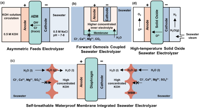
图9 膜电解槽的四大创新方向:(a) 不对称进料电解槽;(b) 正渗透耦合海水电解槽; (c) 自透气防水膜集成海水电解槽;(d) 高温固体氧化物海水电解槽[119]

Fig.9 Four major innovations of membrane electrolyzers: (a) asymmetric feed electrolyzer; (b) positive osmosis coupling seawater electrolyzer; (c) self-breathable waterproof membrane integrated seawater electrolyzer; (d) high-temperature solid oxide seawater electrolyzer[119]

4.1.1 Asymmetric Feed Electrolyzer

A typical seawater electrolyzer uses a symmetrically alkalized seawater feed to achieve efficiency comparable to state-of-the-art electrolyzers. However, seawater alkalization incurs additional costs. Therefore, achieving efficient seawater electrolysis without using alkaline additives remains a challenge.
In 2020, Strasser et al.[120]developed an asymmetric feed electrolyzer that uses non-alkalized seawater, with a structure shown in Figure 10.The system demonstrates high Cl- resistance and OER selectivity even when the cell potential exceeds 3.0 V. This approach enables direct circulation of neutral seawater at the cathode while pure KOH electrolyte circulates at the anode. In alkaline electrolytes containing Cl-, NiFe-LDH exhibits superior catalytic activity and OER selectivity compared to Ir benchmark catalysts. In 2023, Frisch et al.[121]found that transition metal phosphides/sulfides have demonstrated significant potential as highly active and corrosion-resistant PGM-free catalysts for seawater electrolysis. Due to anodic sulfidation, anodic Cl- rejection is achieved in alkalized seawater. The system exhibits an overpotential below 2.0 V, a current density of up to 1.0 A·cm-2, and stable operation for 100 hours. Additionally, Liu et al.[122]designed a pH-asymmetric electrolyzer that incorporates a Na+ exchange membrane for direct seawater splitting, which prevents Cl- transport to the anode while also inhibiting Cl- corrosion and Mg2+/Ca2+ precipitation. By using a Na+ exchange membrane as a separator, Cl- from the cathode (natural seawater) cannot enter the anode. By employing a flowing electrolyte approach, the issue of Mg2+ and Ca2+ precipitation in near-neutral seawater (pH < 9.5) is mitigated. However, this asymmetric feed technology requires the use of high-quality ion exchange membranes and electrocatalysts to ensure high efficiency and durability.
图10 不对称进料电解槽结构图[120]

Fig.10 The asymmetrically fed electrolyzer[120]

4.1.2 Forward Osmosis-Coupled Seawater Electrolyzer

Reverse osmosis (RO) is one of the most popular membrane processes for seawater treatment. However, a major drawback of this technology is its high energy consumption due to the need to apply high pressure to the RO membrane. As a result, forward osmosis (FO), a more energy-efficient technology, has emerged as a low-cost alternative, as illustrated in Figure 11.
图11 正渗透分解水电解槽示意图

Fig.11 The forward osmosis decomposition water electrolyzer

In 2021, Veroneau and Nocera[123]proposed an electrolyzer design in which FO is used to split water, allowing direct utilization of brine without pre-treatment or purification while circumventing challenges posed by impurities and energy-wasting side reactions. The FO water-splitting system consists of an electrochemical compartment isolated from a non-pure water source by a semipermeable membrane. The FO water-splitting cell is filled with a higher-concentration internal electrolyte buffered at pH 7 and is separated from a 0.6 M NaCl external solution by a cellulose acetate semipermeable membrane. In 2022, Nocera et al.[124]replaced the 0.6 M NaCl external solution with real seawater without any pre-treatment; the resulting concentration gradient induces water flow from the saline solution into the more concentrated electrolyte. When the forward osmosis rate and the effective water-splitting rate are balanced, the concentration gradient is maintained through water splitting. Due to the increased selectivity of the cellulose acetate membrane for Cl-,Ca2+,Mg2+,and CO2,the FO electrolysis of seawater system is scalable and suitable for large-scale H2 production from seawater.

4.1.3 Integrated Seawater Electrolyzer with Self-Ventilated Waterproof Membrane

Although FO technology holds great potential for hydrogen production via seawater electrolysis, ion diffusion between brine and electrolyte still occurs during operation periods of 24–120 hours, indicating that the membrane exhibits a non-ideal ion-separation effect.
To ensure complete separation of pure water from seawater, Xie et al.[125]developed a novel direct seawater splitting system for hydrogen production, as shown in Fig. 12a.The primary design feature of this system is the integration of an in-situ water purification process based on a self-driven phase-change mechanism with a seawater electrolysis unit. This is achieved by using a hydrophobic porous polytetrafluoroethylene-based waterproof and breathable membrane as the gas-phase interface and employing a concentrated KOH solution as a self-damping electrolyte, as shown in Fig. 12b.In this setup, the difference in water vapor pressure between seawater and the KOH electrolyte drives the spontaneous evaporation of seawater, which then diffuses through the membrane to the KOH side, where it re-liquefies. The hydrophobic properties of the membrane prevent impurity ions from seawater, while the micrometer-scale gas diffusion pathways enable the migration of water vapor. This “liquid–gas–liquid” phase-change–migration process provides a feed of pure water generated from natural seawater, while simultaneously preventing impurity ions such as Cl-,Mg2+,and SO42-.Finally, when an equilibrium is established between the water migration rate and the electrolysis rate, the integrated system operates in a continuous and stable manner, producing H2 from real seawater. As shown in Fig. 12c, the system can operate under practical conditions at 250 mA·cm-2 for more than 3200 hours.
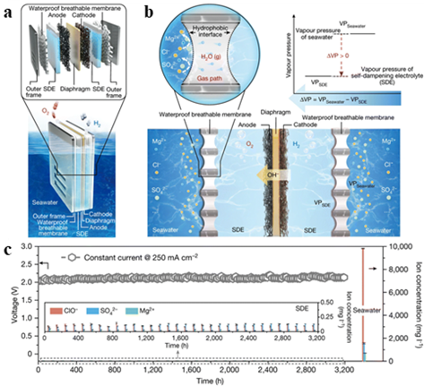
图12 (a) 新型海水电解槽示意图;(b) 通过液-气-液相变的水净化和迁移机制;(c) 在 250 mA·cm-2的恒定电流密度下对放大电解槽的电解耐久性测试[125]

Fig.12 (a) Schematic diagram of a new seawater electrolyzer. (b) Water purification and migration mechanism through liquid-gas-liquid phase transition. (c) Electrolytic durability test of an amplified electrolyzer at a constant current density of 250 mA·cm-2[125]

4.1.4 High-temperature solid oxide seawater electrolyzer

In addition to the aforementioned seawater electrolyzers operating at low temperatures, high-temperature solid oxide seawater electrolyzers driven by thermal energy (800–1000 °C) have also been reported. In high-temperature SOECs, water vapor is evaporated from seawater and transported to the cathode to produce H2.The generated O2-travels through the solid oxide membrane to the anode, where it forms O2. In 2017, Lim et al.[126] investigated the impact of seawater electrolysis on the production of electrolytic steam for H2 generation from simulated seawater (primarily containing Na+, Cl-, K+, Mg2+, Ca2+, Br-, and SO42-). The solid oxide seawater electrolyzer demonstrated durability of up to 70 hours under a constant current density of 0.8 A·cm-2. Moreover, at high temperatures, part of the energy required to split water molecules is supplied in the form of heat, which in turn reduces the demand for electrical energy. This configuration for producing clean steam from low-grade water sources may open up new perspectives beyond the design of electrocatalysts/electrodes. However, seawater electrolysis in SOECs may present challenges, including the long-term durability requirements of the electrodes and the potential damage to the electrolyzer caused by trace impurities in the seawater steam.

4.2 Innovative Electrolysis of Water Method

4.2.1 Bipolar Membrane Water Electrolysis

Bipolar membrane (BPM) technology, as a novel solid polymer water electrolysis method, has attracted considerable attention in the field of seawater electrolysis. A BPM consists of two polymer layers with opposite charges: one layer permits only anions to pass through (anion-exchange membrane layer, AEL, N-type membrane), while the other permits only cations to pass through (cation-exchange membrane layer, CEL, P-type membrane). A PN junction exists at the interface between the anode membrane and the cathode membrane, imparting rectifier-like properties similar to those of semiconductors and giving the BPM unique current–voltage characteristics. As shown in Figure 13a,when a reverse bias is applied (with the CEL facing the cathode and the AEL facing the anode), ion consumption within the membrane increases, leading to an increase in the BPM’s resistance and the electric field strength of the interfacial layer (IL). Consequently, water molecules become polarized and dissociate into H+and OH-. The unique advantage of the BPM lies in its ability to operate the anode and cathode under different pH conditions, thereby allowing the catalysts on each electrode to be optimized independently.
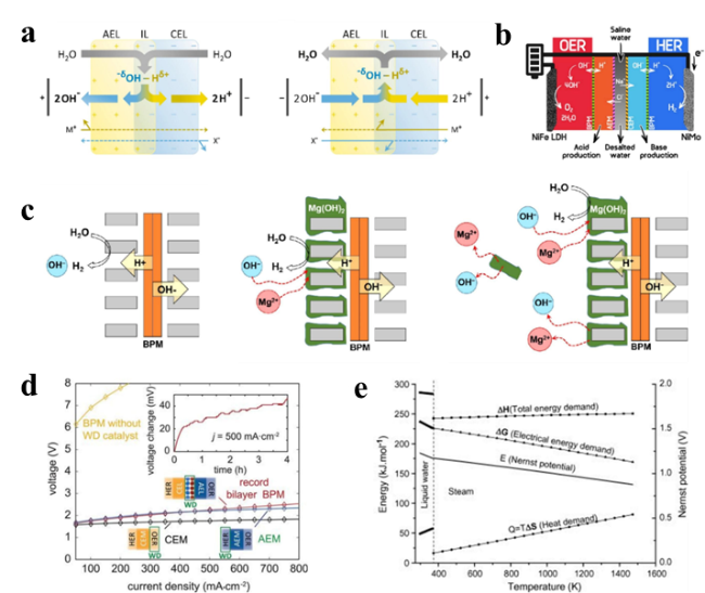
图13 (a) 双极膜原理的示意图[129];(b) 带有AEM、CEM和BPM的海水淡化耦合电催化装置[130];(c) BPM中的无机沉淀和质子通量会以阴极的形式酸化海水[128]

Fig.13 (a) Schematic diagram of the bipolar membrane principle[129]. (b) Coupled electrocatalytic device for desalination with AEM, CEM and BPM [130]. (c) Inorganic precipitation and proton fluxes in BPM acidify seawater in the form of cathodes [128]

Oener et al.[127]introduced various BPM junctions to accurately measure the overpotential of water dissociation. The addition of a water dissociation catalyst significantly enhanced the performance of BPM-based water electrolysis, enabling a current density of 500 mA·cm-2 at a low cell voltage of only 2.2 V, as shown in Fig. 13d.Han et al.[128]used BPM as a separator to control inorganic precipitation by acidifying natural seawater without the need for additional chemicals. In the IL, a reverse bias accelerates the dissociation of water into hydroxide ions and protons, driving them in opposite directions. Inorganic precipitates on the cathode surface isolate the hydroxide ions generated by HER, thereby suppressing the overpotential of HER and the formation of dispersed inorganic deposits (Fig. 13c).

4.2.2 Decoupled Water Electrolysis

Decoupled water electrolysis is a novel electrolysis process that spatially and temporally separates the hydrogen evolution reaction (HER) from the oxygen evolution reaction (OER). At its core, it employs redox mediators or stepwise electrolysis strategies to operate the hydrogen and oxygen production processes independently, thereby avoiding the risks of hydrogen-oxygen mixing and side reactions. This approach breaks through the voltage limitations of traditional electrolyzers and extends electrode lifespan. Due to its unique technological advantages, this technology is particularly well-suited for direct hydrogen production from seawater and for use in highly corrosive electrolyte environments.
Wu et al.[131]synthesized a phenazine-based compound and tested its performance in an acidic two-step decoupled electrolyzer, achieving a current density of 30 A/g over 3000 cycles and a rate performance of 186 mA h/g. Yang et al.[132]proposed a thermoelectrochemical redox-mediated decoupling system. In this system, a temperature-dependent mediator (based on ferricyanide anions) converts low-grade heat into thermal energy, thereby enhancing hydrogen production in decoupled electrolyzers. Wu et al.[133]developed an integrated photovoltaic and decoupled water electrolysis cell, improving the solar-to-hydrogen (STH) conversion efficiency, with a maximum efficiency of up to 30%.

4.2.3 Membrane-free water electrolysis

Membrane-free water electrolysis is a technology that achieves physical separation of hydrogen and oxygen by eliminating the ion-exchange membrane in conventional electrolyzers and optimizing either the electrolyte flow or the electrode structure. At its core, this technology suppresses gas cross-mixing under membrane-free conditions by regulating the electrode spacing, electrolyte flow rate, and bubble dynamics. The technology simplifies system architecture, reduces costs and maintenance complexity, and is suitable for scenarios with low-purity hydrogen requirements or resource-constrained environments. Samir De et al.[134]designed an integrated unit consisting of three parallel microchannels separated by porous electrodes, which can achieve a current density of 747 mA·cm-2 at a voltage of 2.5 V,with a Faraday efficiency of 99.35%. Vanags et al.[135]combined decoupled water splitting with membrane-free electrolysis, proposing a hybrid amphoteric electrolysis system that uses an H xWO3-assisted electrode, with NiOOH present in spatially separated acidic and alkaline cells. The average efficiency of membrane-free decoupled amphoteric electrolysis is approximately 71%, which is higher than the typical efficiency of decoupled electrolysis.

4.2.4 Hybrid Hydrogen Electrolysis

Unlike the temporal separation strategy employed in decoupled water electrolysis, which separates HER from OER for independent operation to extend electrode life, hybrid water electrolysis replaces the reaction pathway by substituting thermodynamically more favorable oxidation reactions for the conventional OER, thereby significantly reducing the anode potential and lowering the total energy consumption for hydrogen production. The primary bottleneck in water electrolysis lies in the slow kinetics of OER, which requires a relatively high anode potential (>1.5 V vs. RHE) to drive the reaction. To address this, researchers have employed organic molecule-based oxidation catalysts to replace the anodic OER, reducing the oxidative overpotential, lowering hydrogen production costs, and enhancing hydrogen production efficiency.
(1) Electrocatalytic oxidation of urea coupled with HER: Urea is a cost-effective, non-flammable, and non-toxic chemical that readily undergoes electrochemical oxidation. Under standard conditions, the thermodynamic voltage for urea electrolysis is 0.37 V, compared to 1.23 V for conventional water splitting. Therefore, coupling the electrochemical oxidation of urea with HER enables hydrogen production via water electrolysis at lower voltages, thereby enhancing energy conversion efficiency.
Feng et al.[136]found that iron oxide–promoted rough nickel/nickel oxide nanorods exhibit high catalytic performance for urea electrocatalytic oxidation coupled with HER, thereby facilitating H2production. After adding 0.33 M urea to the electrolyte, the cell voltage at 10 mA·cm-2decreased significantly from 1.61 V to 1.49 V compared to pure water splitting. In addition, Yin et al.[137]confirmed that by using UOR in place of OER, Ni-WO2(Ni-WO2)@C/NF encapsulated in a carbon hybrid on NF exhibits excellent bifunctional catalytic performance, with a low potential of 1.31 V and -77 mV at 10 mA·cm-2. To elucidate the mechanism of urea electrocatalytic oxidation, Wang et al.[138]proposed a possible UOR mechanism by combining in situ characterization of the β-Ni(OH)2electrode, periodic sampling during the UOR process, and theoretical calculations. The absence of detectable β-Ni(OH)O in the open-circuit stage confirmed the spontaneous reaction between β-Ni(OH)O and urea during periodic UOR sampling (Figure 14a). Furthermore, β-Ni(OH)O during the periodic sampling of the electrocatalytic oxidation reaction can be further detected via in situ Raman spectroscopy (Figure 14b). The formation of β-Ni(OH)O species and the subsequent dehydrogenative oxidation of N2from urea to UOR occur on the β-Ni(OH)2electrode (Figure 14c). In addition, they used DFT calculations to confirm that overcoming a significant energy barrier is required for the formation of the β-Ni(OH)O intermediate on the β-Ni(OH)2base plane (Figure 14d). Protons and electrons are favorably captured by β-Ni(OH)O through a proton-coupled electron transfer process (Figure 14e).
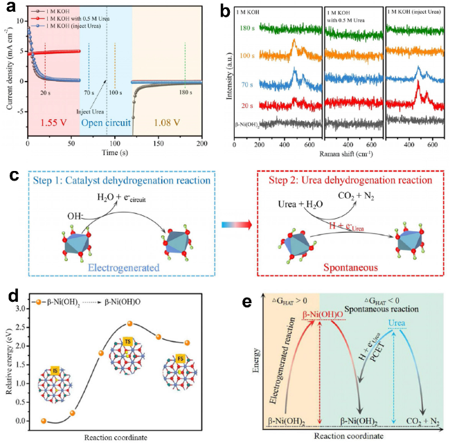
图14 (a) β-Ni(OH)2催化剂在不同电位下的UOR的周期性计时安培测试。 (b) β-Ni(OH)2电极的原位拉曼光谱。(c) β-Ni(OH)2电极上的UOR机制。(d) DFT计算的反应中间体的相对能量。(e) UOR机制的图示[138]

Fig.14 (a) Periodic chronometric amperometric testing of UOR of β-Ni(OH)2 catalyst at different potentials. (b) In-situ Raman spectroscopy of the β-Ni(OH)2 electrode. (c) UOR mechanism on the β-Ni(OH)2 electrode. (d) DFT-calculated relative energy of the reaction intermediate. (e) Diagram of the UOR mechanism[138]

(2) Hydrazine electrocatalytic oxidation coupled with HER: Hydrazine is a rocket fuel and a highly versatile chemical that can be electrochemically oxidized due to its extremely low standard potential (-0.38 V). Consequently, the hydrazine oxidation reaction can significantly reduce the water-splitting voltage in H2production while saving energy. Ma et al.[139]reported a bifunctional electrocatalyst CoS2/TiM nanoarray for HER, coupled with HzOR. The key difference lies in the fact that the dual-electrode system coupling HzOR and HER allows hydrogen evolution to occur at a cell voltage of only 0.81 V to achieve 100 mA·cm-2. This remarkable activity outperforms pure water splitting at the same current density (1.89 V). Tang et al.[140]developed a porous nitrogen-doped carbon-coated cobalt/LaCoO xhybrid nanoparticle (Co/LaCoO x@N-C) as a bifunctional catalyst for both HzOR and HER. This catalyst exhibits outstanding electrochemical activity toward HzOR, achieving 69.2 mA·cm-2at an ultra-low potential of 0.3 V. Its exceptional catalytic activity stems from the synergistic advantages of the abundant catalytic active sites for HzOR in Co/LaCoO x@N-C, along with its excellent charge-transfer capability.
Recently, a robust bifunctional electrocatalyst has been developed by integrating P- and W-co-doped Co3N nanowires (PW-Co3NWA/NF) on NF for HzOR and HER[141]. PW-Co3NWA/NF exhibits superior electrochemical activity for the overall reaction of hydrazine decomposition (OHzS), achieving a current density of 10 mA·cm-2at an ultra-low overpotential of 28 mV (Fig. 15a). Notably, the OHzS system can deliver a high current density of 200 mA·cm-2at an overpotential of 607 mV, highlighting the higher energy efficiency of hydrazine oxidation coupled with HER in H2production (Fig. 15b). Furthermore, using the PW-Co3NWA/NF||Pt/C electrode (Fig. 15c), a direct hydrazine fuel cell (DHzFC) demonstrates a high power density of 46.3 mW·cm-2at a voltage of 0.429 V, underscoring the advantages of this self-powered H2-generation system (Fig. 15d). The system is demonstrated by using the DHzFC to power an OHzS electrolyzer, where vigorous gas evolution is observed (Figs. 15e and f). Gas chromatography is used to measure the H2yield at different time points, with an H2yield of 1.25 mmol·h-1. This also highlights the competitiveness and energy efficiency of this H2-production system (Fig. 15g).
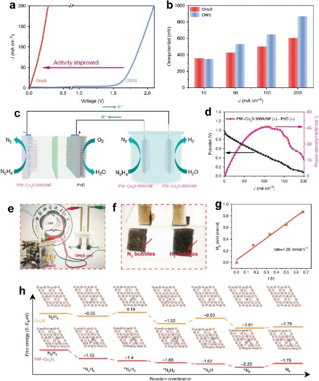
图15 PW-Co3N NWA/NF的电化学性能测量。(a) OHzS和OWS在含有0.1 M肼的1.0 M KOH中电极上的LSV曲线。(b) OHzS和OWSP在不同电流密度下的过电位比较。(c) 将DHzFC和OHzS耦合以实现自供电H2生产。(d) 用于DHzFC的Pt/C电极PW-Co3N NWA/NF的功率密度(P)和电压(V)-电流密度(J)曲线。(e) 自供电H2发生系统的照片。(f) H2生成系统产生的气泡照片。(g) H2代系统不同时间的H2产率[142]

Fig.15 Electrochemical performance measurements of PW-Co3N NWA/NF. (a) LSV curves on the OHzS and OWS electrodes in a 1.0 M KOH containing 0.1 M hydrazine. (b) Overpotential comparison of OHzS and OWSP at different current densities. (c) Coupling DHzFC and OHzS for self-powered H2 production. (d) Power density (P) and voltage (V)-current density (J) curves of the Pt/C electrode PW-Co3N NWA/NF for DHzFC. (e) Photograph of the self-powered H2 generation system. (f) Photographs of bubbles generated by the H2 generation system (g) H2 yield of the H2 generation system at different times [142]

(3) Electrochemical oxidation coupling of alcohols with HER: Alcohols (such as methanol, ethanol, and glycerol) can be converted into their corresponding aldehydes or carboxylic acids via anodic electrochemical oxidation, significantly reducing the electrolysis voltage and suppressing chloride ion interference, thereby enhancing hydrogen production efficiency and equipment lifespan. Moreover, this process can simultaneously produce H2while generating high-value-added chemicals at low energy consumption.
Xu et al.[143]reported a bifunctional electrocatalyst (NC/Ni-Mo-N/NF) that combines water splitting with glycerol electro-oxidation to simultaneously produce H2and formate. The LSV curves demonstrate the superior electrochemical performance of NC/Ni-Mo-N/NF for glucose electrochemical oxidation (GOR), which, compared to OER, delivers a current density of 10 mA·cm-2at a lower potential of 1.16 V (Figure 16a). The Tafel slope for GOR exhibits a smaller value of 114.6 mV·dec-1, indicating more favorable catalytic kinetics than those for OER (Figure 16b). Moreover, this catalyst exhibits high selectivity for the oxidation of glycerol to formate (Figure 16c). In addition, by using NC/Ni-Mo-N/NF as an electrode, simultaneous production of H2and formate is achieved, and an integrated water-splitting system is constructed (Figure 16d). Compared to pure water electrolysis, this system exhibits a low cell voltage of 1.38 V at 10 mA·cm-2(Figure 16e), highlighting the energy-saving benefits of using GOR in place of OER for H2evolution. Zhu et al.[144]confirmed the excellent performance of Ru-NPs@NCNTs in benzyl alcohol electro-oxidation coupled with HER, which can promote H2production. In the presence of benzyl alcohol, Ru-NPs@NCNTs exhibit high catalytic activity and a low potential (1.19 V) at 10 mA·cm-2. The corresponding Tafel slope of 122 mV·dec-1indicates that GOR is more favorable than OER (Figures 16f and g). More importantly, benzyl alcohol can be converted to benzaldehyde with high FE, and the electrolytic cell requires a voltage of 1.36 V to achieve 10 mA·cm-2(Figures 16h and i).
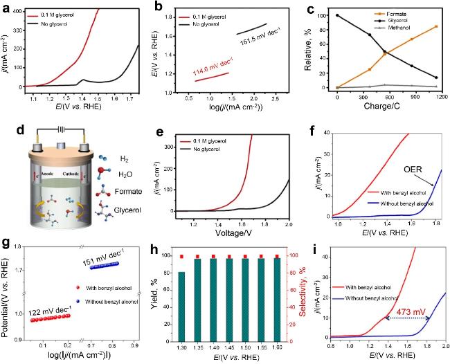
图16 NC/Ni-Mo-N/NF 的电化学性能测量。(a) 含有0.1 M甘油的1 M KOH中GOR的LSV曲线。(b) 相应的塔菲尔斜率。(c) 甘油的消耗量以及甲酸盐和甲醇的收率。(d) HER与GOR整合的示例。(e) 混合电解槽上甘油电化学氧化的LSV曲线[143]。(f) 苯甲醇电化学氧化对Ru-NPs@NCNTs的LSV曲线。(g) 相应的塔菲尔斜率。(h) 苯甲醛在各种电位下的选择性和产率。(i) 苯甲醇在Pt/C||Ru-NPs@NCNTs电解槽[144]

Fig.16 Electrochemical performance measurements of NC/Ni-Mo-N/NF. (a) LSV curve of GOR in 1 M KOH with 0.1 M glycerol. (b) Corresponding tafel slope. (c) Consumption of glycerol and yield of formate and methanol. (d) Example of integration of HER with GOR. (e) LSV curve of electrochemical oxidation of glycerol on a hybrid electrolyzer[143]. (f) LSV curves of benzyl alcohol electrochemical oxidation of Ru-NPs@NCNTs. (g) Corresponding tafel slope. (h) Selectivity and yield of benzaldehyde at various potentials. (i) Benzyl alcohol at Pt/C||RU-NPs@NCNTs Electrolyzer[144]

5 Conclusion and Outlook

In summary, hydrogen production via seawater electrolysis is transitioning from single-material optimization to deep, system-level collaborative innovation. The core of its development lies in enhancing overall efficiency and economic viability through integrated process and system design. Current research focuses on the synergistic optimization of electrolyzer structure, power supply dynamic response, gas–liquid separation efficiency, and gas purification, aiming to overcome key bottlenecks such as chloride-ion corrosion and low electrical conductivity in neutral media. For example, hybrid photovoltaic–wind power supply systems use intelligent control strategies to dynamically allocate power input, prioritizing the integration of fluctuating renewable energy sources and switching to the grid or energy storage systems when necessary, thereby significantly improving energy utilization efficiency. In the future, the miniaturization and intelligentization of power electronic devices will facilitate the distributed deployment of modular electrolytic hydrogen production systems, enabling scenario-specific applications of green hydrogen production, particularly with potential in far-offshore wind power integration and off-grid scenarios.
Material innovation is key to reducing costs and enhancing stability. The development of non-precious metal catalysts (such as transition metal phosphides and sulfides) is gradually replacing precious metals (Ir, Pt), while chloride-ion-resistant composite membranes (such as sulfonated poly(ether ether ketone)-based hybrid membranes), by optimizing ion selectivity and mechanical strength, can extend the lifespan of electrolyzers and reduce maintenance costs. Nanostructural designs (such as three-dimensional porous substrates and atomically dispersed active sites) and heterojunction engineering (metal–oxide heterostructures) further enhance catalytic activity and durability. In addition, the coupled design of high-temperature waste heat recovery systems with electrolyzers can reduce electricity demand by more than 20%; however, the issue of high-temperature material degradation must be further addressed through alloying and interface engineering, laying the material foundation for large-scale applications.
Process innovation is driving breakthrough reductions in hydrogen production energy consumption. Decoupled electrolysis technology separates hydrogen and oxygen evolution reactions in both space and time, thereby avoiding the risk of hydrogen-oxygen mixing and extending electrode lifespan. Bipolar membrane technology leverages pH gradients to precisely create localized acidic/alkaline environments in neutral seawater, significantly suppressing chloride ion side reactions. Hybrid oxidation reactions (such as urea or hydrazine oxidation replacing conventional oxygen evolution) offer thermodynamically more favorable anodic pathways, reducing the hydrogen production voltage from 1.8 V to below 0.5 V and opening up new avenues for ultra-low-energy hydrogen production. Optimization of gas-liquid separation and purification processes is also crucial; novel centrifugal separators and hybrid matrix membranes (such as polyimide-zeolite composite membranes) enhance separation efficiency while reducing pressure drop and costs, though their long-term stability still requires further validation.
In summary, future breakthroughs in seawater electrolysis for hydrogen production depend on multidisciplinary integration and industrial chain collaboration. By using intelligent algorithms to optimize system operating parameters and developing adaptive control strategies, efficient dynamic matching between electrolyzers and renewable energy sources can be achieved. Meanwhile, standardization and large-scale production will significantly reduce the costs of key components (such as membrane electrodes and bipolar plates), accelerating the commercialization of the technology. Driven by the “dual carbon” goals, seawater electrolysis for hydrogen production is poised to become a core pathway for green hydrogen supply, facilitating energy structure transformation and deep decarbonization of industry, thereby providing strategic support for global sustainable development.
[1]
Gunathilake C, Soliman I, Panthi D, Tandler P, Fatani O, Ghulamullah N A, Marasinghe D, Farhath M, Madhujith T, Conrad K, Du Y H, Jaroniec M. Chem. Soc. Rev., 2024, 53(22): 10900.

[2]
Amini Horri B, Ozcan H. Curr. Opin. Green Sustain. Chem., 2024, 47: 100932.

[3]
Koumi Ngoh S, Njomo D. Renew. Sustain. Energy Rev., 2012, 16(9): 6782.

[4]
Kasai S. Int. J. Hydrog. Energy, 2014, 39(36): 21358.

[5]
Mahapatra M K, Singh P. Chapter 24-Fuel Cells: Energy Conversion Technology, in Future Energy (Second Edition). Eds.: Letcher T M. Boston: Elsevier, 2014. 511.

[6]
Niblett D, Delpisheh M, Ramakrishnan S, Mamlouk M. J. Power Sources, 2024, 592: 233904.

[7]
Zhou H R, Chen Z W, Meng W L, Yang S Y. J. Environ. Chem. Eng., 2024, 12(3): 112892.

[8]
Seitz S, Roziková M, Vičarová M, Thirstrup C, DeLeeBeeck L C, Dumańska J, Gonzaga F B, da Cruz Cunha K, Hernán Galli A, Stoica D, Wang H, Haraldsson C, Smirnov A. Metrologia, 2020, 58(1A): 08001.

[9]
Lee S H, Rasaiah J C. J. Chem. Phys., 2011, 135(12): 124505.

[10]
Badea G, Hora C, Maior I, Cojocaru A, Secui C, Filip S M, Dan F. Energies, 2022, 15(22): 8560.

[11]
Mabrak H, Elmazouzi S, Takky D, Naimi Y, Colak I. In 2023 12th International Conference on Renewable Energy Research and Applications (ICRERA). Oshawa: IEEE, 2023, 372.

[12]
Tuluhong A, Chang Q P, Xie L R, Xu Z S, Song T F. Sustainability, 2024, 16(20): 9070.

[13]
Sun H N, Xu X M, Kim H, Jung W, Zhou W, Shao Z P. Energy Environ. Mater., 2023, 6(5): e12441.

[14]
Demnitz M, Lamas Y M, Garcia Barros R L, de Leeuw den Bouter A, van der Schaaf J, Theodorus de Groot M. iScience, 2024, 27(1): 108695.

[15]
Zhu Q P, Yang P H, Zhang T, Yu Z H, Liu K, Fan H J. Appl. Phys. Lett., 2021, 119: 013901.

[16]
Brauns J, Turek T. J. Electrochem. Soc., 2023, 170(6): 064510.

[17]
Wu Q N, Wang Y N, Zhang K X, Xie Z B, Sun K, An W, Liang X, Zou X X. Mater. Chem. Front., 2023, 7(6): 1025.

[18]
Höglinger M, Kartusch S, Eder J, Grabner B, Macherhammer M, Trattner A. Int. J. Hydrog. Energy, 2024, 77: 598.

[19]
Padgett E, Bender G, Haug A, Lewinski K, Sun F X, Yu H R, Cullen D A, Steinbach A J, Alia S M. J. Electrochem. Soc., 2023, 170(8): 084512.

[20]
Zhang X L, Yu P C, Su X Z, Hu S J, Shi L, Wang Y H, Yang P P, Gao F Y, Wu Z Z, Chi L P, Zheng Y R, Gao M R. Sci. Adv., 2023, 9(27): eadh2885.

[21]
Vincent I, Bessarabov D. Renew. Sustain. Energy Rev., 2018, 81: 1690.

[22]
Park H J, Lee S Y, Lee T K, Kim H J, Lee Y M. J. Membr. Sci., 2020, 611: 118355.

[23]
Ha J S, Park Y, Jeong J Y, Lee S H, Lee S J, Kim I T, Park S H, Jin H, Kim S M, Choi S, Kim C, Choi S M, Kang B K, Lee H M, Park Y S. Adv. Sci., 2024, 11(25): 2401782.

[24]
Khataee A, Shirole A, Jannasch P, Krüger A, Cornell A. J. Mater. Chem. A, 2022, 10(30): 16061.

[25]
Li K, Yu S L, Li D G, Ding L, Wang W T, Xie Z Q, Park E J, Fujimoto C, Cullen D A, Kim Y S, Zhang F Y. ACS Appl. Mater. Interfaces, 2021, 13(43): 50957.

[26]
Zhang Q Q, Chang Z S, Fu M K, Ren T, Li X. Appl. Therm. Eng., 2023, 229: 120603.

[27]
Corigliano O, Pagnotta L, Fragiacomo P. Sustainability, 2022, 14(22): 15276.

[28]
Tong W M, Forster M, Dionigi F, Dresp S, Sadeghi Erami R, Strasser P, Cowan A J, Farràs P. Nat. Energy, 2020, 5(5): 367.

[29]
Halevy I, Bachan A. Science, 2017, 355(6329): 1069.

[30]
Gao F Y, Yu P C, Gao M R. Curr. Opin. Chem. Eng., 2022, 36: 100827.

[31]
Kang X, Yang F N, Zhang Z Y, Liu H M, Ge S Y, Hu S Q, Li S H, Luo Y T, Yu Q M, Liu Z B, Wang Q, Ren W C, Sun C H, Cheng H M, Liu B L. Nat. Commun., 2023, 14: 3607.

[32]
Sohrabnejad-Eskan I, Goryachev A, Exner K S, Kibler L A, Hensen E J M, Hofmann J P, Over H. ACS Catal., 2017, 7(4): 2403.

[33]
Liang J, Cai Z W, Li Z X, Yao Y C, Luo Y S, Sun S J, Zheng D D, Liu Q, Sun X P, Tang B. Nat. Commun., 2024, 15: 2950.

[34]
Kuang Y, Kenney M J, Meng Y T, Hung W H, Liu Y J, Huang J E, Prasanna R, Li P S, Li Y P, Wang L, Lin M C, McGehee M D, Sun X M, Dai H J. Proc. Natl. Acad. Sci. U. S. A., 2019, 116(14): 6624.

[35]
Liu W, Yu J G, Sendeku M G, Li T S, Gao W Q, Yang G T, Kuang Y, Sun X M. Angew. Chem. Int. Ed., 2023, 62(40): e202309882.

[36]
Shen W C, Hu T T, Liu X Y, Zha J J, Meng F Q, Wu Z K, Cui Z L, Yang Y, Li H, Zhang Q H, Gu L, Liang R Z, Tan C L. Nat. Commun., 2022, 13: 3384.

[37]
Shi Y M, Du W, Zhou W, Wang C H, Lu S S, Lu S Y, Zhang B. Angew. Chem. Int. Ed., 2020, 59(50): 22470.

[38]
Chaudhari N, Jin H, Kim B, Lee K. Nanoscale, 2017, 9(34): 1223.

[39]
Ren G, Hao Q Y, Mao J, Liang L M, Liu H, Liu C C, Zhang J. Nanoscale, 2018, 10(36): 17347.

[40]
Gao X Q, Chen Y D, Sun T, Huang J M, Zhang W, Wang Q, Cao R. Energy Environ. Sci., 2020, 13(1): 174.

[41]
Fei B, Chen Z L, Liu J X, Xu H B, Yan X X, Qing H L, Chen M, Wu R B. Adv. Energy Mater., 2020, 10(41): 2001963.

[42]
Zhao Y Q, Jin B, Zheng Y, Jin H Y, Jiao Y, Qiao S Z. Adv. Energy Mater., 2018, 8(29): 1801926.

[43]
Jiang Y, Gao S S, Liu J L, Xu G C, Jia Q, Chen F S, Song X M. Nanoscale, 2020, 12(21): 11573.

[44]
Wang X D, Chen H Y, Xu Y F, Liao J F, Chen B X, Rao H S, Kuang D B, Su C Y. J. Mater. Chem. A, 2017, 5(15): 7191.

[45]
Li J Y, Xia Z M, Zhou X M, Qin Y B, Ma Y Y, Qu Y Q. Nano Res., 2017, 10(3): 814.

[46]
Han X, Wu X, Deng Y, Liu J, Lu J, Zhong C, Hu W. Adv. Energy Mater., 2018, 8(24): 1800935.

[47]
Mishra A, Shetti N P, Basu S M, Raghava Reddy K, Aminabhavi T M. ChemElectroChem, 2019, 6(23): 5771.

[48]
Zhang C, Bhoyate S, Hyatt M, Neria B L, Siam K, Kahol P K, Ghimire M, Mishra S R, Perez F, Gupta R K. Surf. Coat. Technol., 2018, 347: 407.

[49]
Hao W J, Wu R B, Huang H, Ou X, Wang L C, Sun D L, Ma X H, Guo Y H. Energy Environ. Sci., 2020, 13(1): 102.

[50]
Zhou B H, Gao R J, Zou J J, Yang H M. Small, 2022, 18(27): 2202336.

[51]
Song S W, Wang Y H, Zhou S Y, Gao H W, Tian X Q, Yuan Y G, Li W, Zang J B. ACS Appl. Energy Mater., 2022, 5(2): 1810.

[52]
Li J, Liu Y, Chen H, Zhang Z, Zou X. Adv. Funct. Mater., 2021, 31(27): 2101820.

[53]
Li L, Zhang G W, Wang B, Yang S C. Appl. Catal. B Environ., 2022, 302: 120847.

[54]
Petrykin V, Macounova K, Shlyakhtin O  , Krtil P. Angew. Chem. Int. Ed., 2010, 49(28): 4813.

[55]
Zhang X Y, Feng C, Dong B, Liu C G, Chai Y M. Adv. Mater., 2023, 35(13): 2207066.

[56]
Cui C M, Zhang H N, Wang D, Song J H, Yang Y. Materials, 2024, 17: 4057.

[57]
Xu W C, Fan G L, Zhu S L, Liang Y Q, Cui Z D, Li Z Y, Jiang H, Wu S L, Cheng F Y. Adv. Funct. Mater., 2021, 31(48): 2107333.

[58]
Zhao M X, Yang M Y, Huang W J, Liao W C, Bian H D, Chen D Z, Wang L, Tang J N, Liu C. ChemCatChem, 2021, 13(9): 2138.

[59]
Yuan W J, Cui Z D, Zhu S L, Li Z Y, Wu S L, Liang Y Q. Electrochim. Acta, 2021, 365: 137366.

[60]
Ros C, Murcia-López S, Garcia X, Rosado M, Arbiol J, Llorca J, Morante J R. ChemSusChem, 2021, 14(14): 2872.

[61]
Zang W J, Sun T, Yang T, Xi S B, Waqar M, Kou Z K, Lyu Z Y, Feng Y P, Wang J, Pennycook S J. Adv. Mater., 2021, 33(8): 2003846.

[62]
Zhang X L, Zhang Y, Li F W, Easton C D, Bond A M, Zhang J. Appl. Catal. B Environ., 2019, 249: 227.

[63]
Liu L P, Wang J Y, Ren Z B, Wang F, Wang T, Guo H J. Int. J. Hydrog. Energy, 2023, 48(62): 23885.

[64]
Li W X, Sun Z C, Ye X M, He Y M. Int. J. Hydrog. Energy, 2024, 81: 918.

[65]
Ying Y P, Kamarudin S K, Masdar M S. Int. J. Hydrog. Energy, 2018, 43(33): 16068.

[66]
Parnian M J, Rowshanzamir S, Gashoul F. Energy, 2017, 125: 614.

[67]
Zhou Z P, Zholobko O, Wu X F, Aulich T, Thakare J, Hurley J. Energies, 2021, 14(1): 135.

[68]
Iulianelli A, Basile A. Int. J. Hydrog. Energy, 2012, 37(20): 15241.

[69]
Tahrim A A, Amin I N H M. J. Appl. Membr. Sci. Technol., 2018, 23(1): 37.

[70]
Yagizatli Y, Sahin A, Ar I. Int. J. Hydrog. Energy, 2022, 47(95): 40445.

[71]
Sgreccia E, Di Vona M L, Knauth P. Int. J. Hydrog. Energy, 2011, 36(13): 8063.

[72]
Li X, Sabir I. Int. J. Hydrog. Energy, 2005, 30(4): 359.

[73]
Lee S J, Lai J J, Huang C H. J. Power Sources, 2005, 145(2): 362.

[74]
Kraytsberg A, Auinat M, Ein-Eli Y. J. Power Sources, 2007, 164(2): 697.

[75]
Zuo Y, Li S R, Zhao X H, Tang Y M. Surf. Coat. Technol., 2017, 330: 249.

[76]
Rajaei V, Rashtchi H, Raeissi K, Shamanian M. Int. J. Hydrog. Energy, 2017, 42(20): 14264.

[77]
Orsi A, Kongstein O E, Hamilton P J, Oedegaard A, Svenum I H, Cooke K. J. Power Sources, 2015, 285: 530.

[78]
Hu Y Q, Chen F, Xiang Z D. J. Power Sources, 2019, 414: 167.

[79]
Peng S, Xu J, Li Z Y, Jiang S Y, Munroe P, Xie Z H, Lu H. Ceram. Int., 2020, 46(3): 2743.

[80]
Chen P, Fang F F, Zhang Z N, Zhang W, Wang Y X. Int. J. Hydrog. Energy, 2017, 42(17): 12593.

[81]
Madadi F, Rezaeian A, Edris H, Zhiani M. Mater. Chem. Phys., 2019, 238: 121911.

[82]
Ben Jadi S, El Jaouhari A, Aouzal Z, El Guerraf A, Bouabdallaoui M, Wang R, Bazzaoui E A, Bazzaoui M. Mater. Today Proc., 2020, 22: 52.

[83]
Kontrosh L V, Kalinovsky V S, Khramov A V, Kontrosh E V. Clean. Eng. Technol., 2021, 4: 100186.

[84]
Purnami, Hamidi N, Sasongko M N, Widhiyanuriyawan D, Wardana I N G. Int. J. Hydrog. Energy, 2020, 45(38): 19370.

[85]
Almomani F, Shawaqfah M, Alkasrawi M. Int. J. Hydrog. Energy, 2022, 47(5): 3294.

[86]
Jia J Y, Seitz L C, Benck J D, Huo Y J, Chen Y S, Ng J W D, Bilir T, Harris J S, Jaramillo T F. Nat. Commun., 2016, 7: 13237.

[87]
Ntziachristos L, Kouridis C, Samaras Z, Pattas K. Renew. Energy, 2005, 30(10): 1471.

[88]
Abdel-Basset M, Gamal A, Chakrabortty R K, Ryan M J. Int. J. Hydrog. Energy, 2021, 46(5): 4567.

[89]
Uwineza L, Kim H G, Kim C K. Energy Strategy Rev., 2021, 33: 100607.

[90]
Wang B, Deng Z W, Zhang B C. Energy, 2022, 238: 121833.

[91]
Ghenai C, Rasheed M A, Alshamsi M J, Alkamali M A, Ahmad F F, Inayat A. Case Stud. Therm. Eng., 2020, 22: 100773.

[92]
Trinke P, Haug P, Brauns J, Bensmann B, Hanke-Rauschenbach R, Turek T. J. Electrochem. Soc., 2018, 165(7): F502.

[93]
David M, Bianchi F, Ocampo-Martinez C, Sánchez-Peña R. J. Frankl. Inst., 2021, 358(8): 4373.

[94]
Qi R M, Gao X P, Lin J, Song Y H, Wang J P, Qiu Y W, Liu M. Int. J. Hydrog. Energy, 2021, 46(73): 35997.

[95]
Wang Q Q, Chen J Q, Wang C S, Ji Y P, Shang C, Zhang M, Shi Y, Ding G D. J. Petrol. Sci. Eng., 2023, 220: 111218.

[96]
Yang L S, Cui Y, Wang Z, Sun P P, Cui W W, Wang C P. Asia Pac. J. Chem. Eng., 2024, 19: e2978.

[97]
Yang L S, Xu M H, Wang J J, Song L, Wang J X. Chin. J. Chem. Eng., 2021, 33: 83.

[98]
Dong J P, Chen G H, Wang W W, Fan J L, Li J L, Zhang P. Chem. Eng. Sci., 2022, 251: 117442.

[99]
Wei P K, Wang D, Niu P M, Pang C K, Liu M. Int. J. Multiph. Flow, 2020, 124: 103190.

[100]
Ninahuanca H E M, Stel H, Morales R E M, Ofuchi C, da Silva M J, Neves F Jr. AlChE. J., 2016, 62(6): 2213.

[101]
Zeng X B, Fan G M, Xu J X, Liu A T, Xu Y F, Yan C Q. Chem. Eng. Res. Des., 2020, 160: 561.

[102]
Liu Z, Ji Z L, Wu X L, Ma H, Zhao F T, Hao Y T. Sep. Purif. Technol., 2016, 170: 146.

[103]
Xie J, Xu J L, Liang C, She Q T, Li M J. Energy, 2019, 172: 661.

[104]
Kim G J, Shin J H, Chang Hong S. Int. J. Hydrog. Energy, 2020, 45(35): 17276.

[105]
Lalik E, Kosydar R, Tokarz-Sobieraj R, Witko M, Szumełda T, Kołodziej M, Rojek W, Machej T, Bielańska E, Drelinkiewicz A. Appl. Catal. A Gen., 2015, 501: 27.

[106]
Yasnev I M, Mel’nichenko A N, Gurskii V S. Russ. J. Appl. Chem., 2020, 93(6): 927.

[107]
Dawood F, Anda M, Shafiullah G M. Int. J. Hydrog. Energy, 2020, 45(7): 3847.

[108]
Schorer L, Schmitz S, Weber A. Int. J. Hydrog. Energy, 2019, 44(25): 12708.

[109]
Brea P, Delgado J A, Águeda V I, Gutiérrez P, Uguina M A. Microporous Mesoporous Mater., 2019, 286: 187.

[110]
You Y W, Lee D G, Yoon K Y, Moon D K, Kim S M, Lee C H. Int. J. Hydrog. Energy, 2012, 37(23): 18175.

[111]
Lopes F V S, Grande C A, Rodrigues A E. Fuel, 2012, 93: 510.

[112]
Tang D, Tan G L, Li G W, Liang J G, Ahmad S M, Bahadur A, Humayun M, Ullah H, Khan A, Bououdina M. J. Energy Storage, 2023, 64: 107196.

[113]
Klopčič N, Grimmer I, Winkler F, Sartory M, Trattner A. J. Energy Storage, 2023, 72: 108456.

[114]
Sadeq A M, Homod R Z, Hussein A K, Togun H, Mahmoodi A, Isleem H F, Patil A R, Moghaddam A H. Sci. Total Environ., 2024, 939: 173622.

[115]
Dube S, Gorimbo J, Moyo M, Okoye-Chine C G, Liu X Y. J. Environ. Chem. Eng., 2023, 11(1): 109194.

[116]
Li M, Yan X R, Cong S Z, Shi P X, Guo Z C, Wang C X, Luo C L, Wang Z, Liu X L. J. Membr. Sci., 2024, 700: 122698.

[117]
Li P Y, Wang Z, Qiao Z H, Liu Y N, Cao X C, Li W, Wang J X, Wang S C. J. Membr. Sci., 2015, 495: 130.

[118]
Saini N, Awasthi K. Sep. Purif. Technol., 2022, 282: 120029.

[119]
Liu Y, Wang Y, Fornasiero P, Tian G, Strasser P, Yang X-Y. Angew. Chem. Int. Ed., 2024, 63(47): e202412087.

[120]
Dresp S, Ngo Thanh T, Klingenhof M, Brückner S, Hauke P, Strasser P. Energy Environ. Sci., 2020, 13(6): 1725.

[121]
Frisch M L, Thanh T N, Arinchtein A, Hager L, Schmidt J, Brückner S, Kerres J, Strasser P. ACS Energy Lett., 2023, 8(5): 2387.

[122]
Liu J Y, Liu X, Shi H, Luo J H, Wang L, Liang J S, Li S Z, Yang L M, Wang T Y, Huang Y H, Li Q. Appl. Catal. B Environ., 2022, 302: 120862.

[123]
Veroneau S S, Nocera D G. Proc. Natl. Acad. Sci. U. S. A., 2021, 118(9): e2024855118.

[124]
Veroneau S S, Hartnett A C, Thorarinsdottir A E, Nocera D G. ACS Appl. Energy Mater., 2022, 5(2): 1403.

[125]
Xie H P, Zhao Z Y, Liu T, Wu Y F, Lan C, Jiang W C, Zhu L Y, Wang Y P, Yang D S, Shao Z P. Nature, 2022, 612(7941): 673.

[126]
Lim C K, Liu Q L, Zhou J, Sun Q, Chan S H. J. Power Sources, 2017, 342: 79.

[127]
Oener S Z, Foster M J, Boettcher S W. Science, 2020, 369(6507): 1099.

[128]
Han J H, Jwa E, Lee H J, Kim E J, Nam J Y, Hwang K S, Jeong N, Choi J, Kim H, Jeung Y C, Chung T D. Chem. Eng. J., 2022, 429: 132383.

[129]
Pärnamäe R, Mareev S, Nikonenko V, Melnikov S, Sheldeshov N, Zabolotskii V, Hamelers H V M, Tedesco M. J. Membr. Sci., 2021, 617: 118538.

[130]
Kim B J, Shon H K, Han D, Park H. Desalination, 2023, 551: 116431.

[131]
Wu K X, Li H Z, Liang S K, Ma Y Y, Yang J P. Angew. Chem. Int. Ed., 2023, 62(23): e202303563.

[132]
Yang W, Qiu Y, Bao J J, Luo C H, Zhao Q. Ind. Eng. Chem. Res., 2023, 62(25): 9932.

[133]
Wu T C, Hu Y, Li M, Han B, Liang Z F, Geng D S. Int. J. Hydrog. Energy, 2023, 48(91): 35552.

[134]
Samir De B, Singh A, Ji Dixit R, Khare N, Elias A, Basu S. Chem. Eng. J., 2023, 452: 139433.

[135]
Vanags M, Kulikovskis G, Kostjukovs J, Jekabsons L, Sarakovskis A, Smits K, Bikse L, Šutka A. Energy Environ. Sci., 2022, 15(5): 2021.

[136]
Gu X C, Yang D W, Liu Z, Wang S L, Feng L G. Electrochim. Acta, 2020, 353: 136516.

[137]
Shen F, Jiang W J, Qian G F, Chen W, Zhang H, Luo L, Yin S B. J. Power Sources, 2020, 458: 228014.

[138]
Chen W, Xu L T, Zhu X R, Huang Y C, Zhou W, Wang D D, Zhou Y Y, Du S Q, Li Q L, Xie C, Tao L, Dong C L, Liu J L, Wang Y Y, Chen R, Su H, Chen C, Zou Y Q, Li Y F, Liu Q H, Wang S Y. Angew. Chem. Int. Ed., 2021, 60(13): 7297.

[139]
Ma X, Wang J M, Liu D N, Kong R M, Hao S, Du G, Asiri A M, Sun X P. New J. Chem., 2017, 41(12): 4754.

[140]
Gao L, Xie J F, Liu S S, Lou S S, Wei Z M, Zhu X J, Tang B. ACS Appl. Mater. Interfaces, 2020, 12(22): 24701.

[141]
Li Y P, Zhang J H, Liu Y, Qian Q Z, Li Z Y, Zhu Y, Zhang G Q. Sci. Adv., 2020, 6(44): eabb4197.

[142]
Liu Y, Zhang J H, Li Y P, Qian Q Z, Li Z Y, Zhu Y, Zhang G Q. Nat. Commun., 2020, 11: 1853.

[143]
Xu Y, Liu M Y, Wang S Q, Ren K L, Wang M Z, Wang Z Q, Li X N, Wang L, Wang H J. Appl. Catal. B Environ., 2021, 298: 120493.

[144]
Zhu P, Shen Y L, Dai L X, Yu Q Y, Zhang Z M, An C H. ACS Appl. Mater. Interfaces, 2022, 14(1): 1452.

Outlines

/