Home Journals Progress in Chemistry
Progress in Chemistry

Abbreviation (ISO4): Prog Chem      Editor in chief: Jincai ZHAO

About  /  Aim & scope  /  Editorial board  /  Indexed  /  Contact  / 
Review

TiO2-Based Nanomaterials for High-Efficiency Photocatalytic Hydrogen Production

  • Jiarui Zhang 1, 2 ,
  • Yongchao Yang , 1, 3, *
Expand
  • 1 CAS Key Laboratory of Nanosystem and Hierarchical Fabrication, CAS Center for Excellence in Nanoscience,National Center for Nanoscience and Technology, Beijing 100190, China
  • 2 School of Materials and Energy, Guangdong University of Technology, Guangzhou 510006, China
  • 3 School of Chemical and Biomolecular Engineering, The University of Sydney, NSW 2006, Australia

Received date: 2025-06-20

  Revised date: 2025-10-10

  Online published: 2026-02-04

Supported by

FH Loxton fellowship of the University of Sydney (USYD)

Abstract

In response to the global energy crisis and environmental challenges,photocatalytic hydrogen (H2) production has emerged as a sustainable alternative toward clean energy conversion. Among diverse photocatalysts investigated,TiO2-based nanomaterials have attracted significant attention due to their unique physicochemical properties,such as high chemical stability,strong redox capacity and tunable electronic structures,along with high cost-effectiveness. Extensive research on TiO2-based photocatalysts proves their enormous potential in the field of H2 production. This timely and critical review explores the recent advances in TiO2-based photocatalysts,discussing their distinctive advantages and synthesis methods in photocatalytic H2 production. Modification strategies,such as elemental doping (e.g.,precious metals,non-precious metals and non-metals),morphology engineering and composite formation,are summarised to improve photocatalytic efficiency. Advanced in/ex situ characterization techniques employed to probe photocatalytic mechanisms are also highlighted. Finally,major challenges,such as limited visible-light activity and charge recombination,are outlined,with perspectives on emerging TiO2-based nanomaterials and design strategies to overcome current bottlenecks. And the research focus in the future is prospected,such as atomic interface engineering,machine learning auxiliary material design and large-scale preparation technology. This work aims to provide insights into the rational design of TiO2-based photocatalysts for next-generation H2 production systems.

Contents

1 Introduction

2 Unique advantages of TiO2-based photocatalysts

3 Various preparation methods of TiO2-based photocatalysts

3.1 Top-down synthesis

3.2 Bottom-up synthesis

4 Design strategies of TiO2-based photocatalysts for H2 production

4.1 Elemental doping

4.2 Morphology engineering

4.3 Composite

5 Advanced characterization techniques for TiO2-based photocatalysts

5.1 X-ray diffraction (XRD)

5.2 XPS

5.3 X-ray absorption spectroscopy (XAS)

5.4 TEM and SEM

5.5 Raman and FTIR

6 Conclusions and outlook
Cite this article

Jiarui Zhang , Yongchao Yang . TiO2-Based Nanomaterials for High-Efficiency Photocatalytic Hydrogen Production[J]. Progress in Chemistry, 2026 , 38(2) : 210 -236 . DOI: 10.7536/PC20250622

1 Introduction

The accelerating depletion of fossil fuels,coupled with mounting concerns over global warming and environmental degradation,has intensified the global search for clean and sustainable energy alternatives[1-3]. Among the various emerging technologies,photocatalytic hydrogen (H2) production has garnered significant attention as a promising route for harvesting solar energy—an abundant,renewable,and universally accessible resource—to generate carbon-free fuel[4-5]. H2 possesses a high gravimetric energy density and yields only water as a by-product upon combustion,positioning it as a cornerstone of future low-carbon energy infrastructures[4,6-7]. Photocatalysis leverages semiconductor materials to absorb sunlight and drive thermodynamically uphill chemical reactions,notably the splitting of water into H2 and oxygen[8-10]. This light-to-chemical conversion process is inherently sustainable,scalable,and environmentally benign. From a mechanistic perspective,photocatalytic water splitting involves three fundamental steps:(i) the absorption of incident photons and generation of electron-hole pairs,(ii) the spatial separation and migration of charge carriers to reactive sites,and (iii) surface redox reactions involving water molecules. Each of these steps is governed by distinct physicochemical parameters that collectively determine the system’s solar-to-H2 (STH) efficiency. The band structure of the photocatalyst dictates its ability to harness specific regions of the solar spectrum,while the dynamics of charge separation and transport are critical in minimizing recombination losses. Simultaneously,the surface area,facet orientation,and nanostructure morphology influence adsorption,catalytically active site availability,and interfacial kinetics. Hence,the rational design of photocatalysts necessitates a holistic understanding of structure-property-function relation-ships to maximize reaction efficiency under solar irradiation[11].
An ideal photocatalyst ought to exhibit high activity under visible light,possess an optimal band gap,maintain stable surface chemistry,and demonstrate efficient charge separation to minimize electron-hole pair recombination. In photocatalytic H2 production,the fundamental mechanism involves photon absorption by the photocatalyst,which excites electrons from the valence band to the conduction band. These photogenerated electrons and the corresponding holes (positive charges) can then drive redox reactions,such as the reduction of water to H2 and the oxidation of water to oxygen[12-13]. Among the most extensively studied photocatalysts,ZnO and g-C3N4 have undergone significant modifications and optimizations in recent years,including the development of Ag/CeO2/ZnO nanocomposites,ZnO-CuxO heterostructures,and Z-scheme heterojunction CeO2/g-C3N4 nanocomposites[14-15]. However,ZnO suffers from limited visible light absorption,while g-C3N4 is prone to rapid electron-hole recombination and exhibits poor visible light absorption. In contrast,TiO2 stands out due to its ease of synthesis,chemical stability,and efficiency in driving redox reactions under UV light. While TiO2 is widely regarded as a benchmark photocatalyst,its performance is hindered by its large band gap (~3.2 eV),which restricts its light absorption to the UV region,accounting for only a small fraction of the solar spectrum. Despite these limitations,TiO2 has garnered significant attention as a “rising star” in photocatalysis due to its unique physicochemical properties,including high chemical stability,non-toxicity,and strong oxidative capability under UV light[16].
TiO2 exists in three main crystalline phases:anatase,rutile,and brookite,with anatase generally regarded as the most active phase for photocatalytic reactions. In fact,anatase and rutile phases exhibit higher photocatalytic efficiency than brookite[17]. The structural characteristics,including crystal structure,band gap,and electronic properties,are crucial in determining its photocatalytic performance. The band gap of TiO2 dictates its ability to absorb photons and generate electron-hole pairs,while its crystalline structure influences charge transport and recombination rates. TiO2 has been widely applied in various photocatalytic H2 production systems,ranging from powder suspensions to immobilized thin films. Several modifications,such as doping with metal and non-metal ions,coupling with other semiconductors,and exploiting surface plasmon resonance (SPR) effects,have been employed to enhance its photocatalytic activity under visible light[18-19]. Representative studies have demonstrated the effectiveness of these strategies in improving H2 production efficiency. Notably,Qian et al.[20] hybridized TiO2 with metal sulfides (e.g.,CdS,MoS2,CuS),significantly enhancing the catalytic activity of TiO2. Similarly,Udayabhanu et al.[21] synthesized pure nanomaterials and 1~4 Cu-TiO2/CuO composites via ultrasonic irradiation assisted by green surfactants,leading to substantial improvements in TiO2 catalytic performance[16].
Despite its many merits,TiO2-based photocatalysts are constrained by limited visible-light absorption and rapid charge carrier recombination. To address these limitations,extensive efforts have been devoted to tailoring the structural and electronic properties of TiO2 through a variety of modification strategies. This review provides a comprehensive overview of the unique advantages of TiO2 as a photocatalyst for hydrogen production and critically examines the latest progress in modification strategies,including doping (e.g.,precious metals,non-precious metals and non-metals),morphology engineering,and heterojunction construction. We focus,in particular,on recent advancements in synthetic methodologies and rational design approaches for TiO2-based materials applied in photocatalytic hydrogen evolution. In addition,we highlight the key characterization techniques used to probe the structure-activity relationship and elucidate how these insights have guided material development. Finally,we outline the current challenges and future opportunities in this rapidly evolving field,and analyze research priorities over the next five years,such as atomic-scale interface engineering,machine learning-assisted material design,and large-scale preparation techniques,aiming to provide a forward-looking perspective that will inform the design of next-generation TiO2-based photocatalysts for efficient and scalable solar-to-hydrogen conversion.

2 Unique advantages of TiO2-based photocatalysts

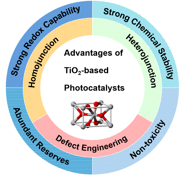
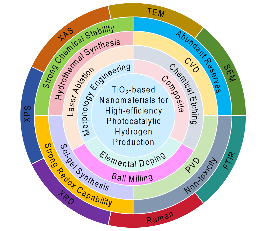
Beyond its intrinsic advantages,TiO2 offers exceptional structural tunability,enabling the precise modulation of its physicochemical properties to meet photocatalytic requirements[22]. The flexibility of the TiO2 lattice accommodates a wide range of chemical substitutions,surface reconstructions,and heterointerface formations,allowing researchers to fine-tune light absorption,charge carrier dynamics,and surface redox activity without compromising stability (Fig.1). A diverse array of modification strategies,including elemental doping,surface functionalization,and the formation of heterojunctions with complementary semiconductors,has been employed to broaden visible-light responsiveness and suppress charge recombination. These approaches exploit the multiscale nature of TiO2 design,spanning atomic-level dopant control to mesoscale morphological engineering. Advancements in synthetic methodologies have further expanded the design space of TiO2-based materials. Techniques such as in situ deposition,hydrothermal crystallization,ionic-liquid-assisted microwave synthesis,photoreduction,and sol-gel processing enable precise control over particle size,crystallinity,defect states,and interfacial architecture[23]. These routes,broadly classified into top-down and bottom-up approaches,provide complementary advantages in tailoring surface area,porosity,and electronic structure. Together,these synthetic and structural strategies empower the rational design of high-performance TiO2 photocatalysts. In the following sections,we explore how such design principles translate into enhanced structure-activity relationships and practical applications in solar-driven H2 production.
图1 TiO2基光催化剂的独特优势示意图

Fig.1 Scheme of the unique advantages of TiO2-based photocatalysts

The band gap of TiO2 is primarily determined by the electronic state of its atomic orbitals. Defect engineering,which alters the lattice structure of TiO2 and introduces electronic defect states into its energy level structure,plays a crucial role in reducing the band gap and broadening the material’s light absorption range. Dalanta et al.[24] demonstrated that Co doping could reduce the band gap of TiO2 from 3.10 to 3.00 eV,thereby expanding its light absorption range. Moreover,increasing the concentration of defect states further enhances the light absorption capabilities of TiO2. In addition to the reduction in band gap,the shape of the defect bands—such as those associated with doping and vacancies—affects the effective mass of photogenerated carriers,which in turn influences their mobility and diffusivity. Doustkhah et al.[25] found that,compared to Cl doping,oxygen vacancy-induced defect bands are relatively flat,resulting in a heavier effective mass for the carriers. Consequently,Cl doping more effectively improves the shape of the defect band,reducing the effective mass of photogenerated carriers,increasing their mobility,and thereby enhancing photocatalytic H2 evolution activity.
Unlike oxygen vacancies,the introduction of Ti vacancies can regulate the electron spin properties of TiO2,thereby enhancing its charge separation ability and surface reaction efficiency. In fact,TiO2 with Ti vacancies exhibits a photocatalytic H2 evolution rate 20 times higher than that of stoichiometric TiO2. However,defect engineering does not always guarantee improved catalytic activity. This is because the intermediate energy levels introduced by defects can act as recombination centers for electron-hole pairs,increasing the recombination probability of photogenerated carriers. Thus,while reducing both bulk and surface defects can promote carrier separation and improve H2 evolution efficiency,it also leads to a decrease in the material’s light absorption capacity. Constructing double or multiple defects has been proposed as an effective strategy to balance these opposing effects[23].
TiO2-based catalysts can also benefit from various structural designs,with the homojunction being one of the most studied. Homojunctions containing TiO2 typically exhibit high-quality contact interfaces with minimal lattice mismatch,which promotes the separation and transfer of photoexcited carriers. The anatase-rutile homojunction is particularly well-studied due to its excellent photocatalytic H2 evolution performance. For instance,Ruan et al.[26] synthesized anatase TiO2 nanorods (a-TiO2) on hydrogenated rutile TiO2 nanorods (H-TiO2) by an epitaxial growth method,creating an a-TiO2/H-TiO2 homojunction. This material demonstrated an impressive apparent quantum efficiency of 45.6% under a 365 nm light source and exhibited excellent photocatalytic H2 evolution activity under UV-visible light irradiation.
Apart from homojunctions,heterojunctions have significant potential for enhancing photocatalytic performance. During the formation of a heterojunction,electrons from both sides of the interface tend to flow toward the semiconductor with the lower Fermi level until the Fermi level difference is balanced. This results in the formation of a strong internal electric field at the heterojunction interface,which facilitates efficient charge transfer. Among the various heterojunctions,S-scheme and Z-scheme heterojunctions of TiO2 have shown strong redox abilities and high carrier utilization efficiencies. Optimizing the electric field strength at the heterojunction interface can further enhance these properties. For example,Tu et al.[27] doped TiO2 with N,I,F,and Ce elements,which altered the Fermi level and consequently adjusted the electric field strength at the TiO2/CdS heterojunction interface. Doping with I increased the Fermi level difference between TiO2 and CdS,leading to enhanced electric field strength and improved charge separation efficiency,as demonstrated in the I-TiO2/CdS system. Additionally,heterojunctions can be combined with other structural designs,such as crystal facet junctions or multiple heterojunctions,to further enhance charge transfer capabilities[23]. These findings underscore the importance of structural modifications to TiO2,as such changes can significantly influence its photocatalytic performance.

3 Various preparation methods of TiO2-based photocatalysts

One of the leading factors in the use of nanomaterials and their applications in various fields is the synthesis and growth mechanism of nanomaterials and nanostructures. The structure and morphology of TiO2-based photocatalysts depend on the growth and synthesis methods. As shown in Table 1,their preparation methods are mainly divided into top-down and bottom-up synthesis[28-44].
表1 TiO2基光催化剂的主要合成方法总结

Table 1 Summary of the main synthesis methods of TiO2-based photocatalysts

Photocatalysts Synthesis methods Method category Ref
Pd/TiO2-BM Ball milling Top-down 29
Ag/TiO2-BDPR Ball milling Top-down 30
TiO2/graphite Ball milling Top-down 31
TiO2-Pt Laser ablation Top-down 32
TiO2/Y2O3 Laser ablation Top-down 33
Au-TiO2 Laser ablation Top-down 34
CFA/TiO2 Chemical etching Top-down 35
TiO2/Ac-Al-x-y Chemical etching Top-down 36
IL-TiO2 Sol-gel synthesis Bottom-up 37
PAgT Sol-gel synthesis Bottom-up 38
CuO/GQD@TiO2 Hydrothermal synthesis Bottom-up 39
CaTiO3/Cu/TiO2 Hydrothermal synthesis Bottom-up 40
ZnO-TiO2 CVD Bottom-up 41
TiO2-Pd CVD Bottom-up 42
NiO/TiO2 PVD Bottom-up 43
TiO2-Ag PVD Bottom-up 44

Note:BM = ball milling;BDPR = date palm rachis biochar;CFA = coal fly ash;Ac = acid;xy = the treatment conditions of Al plates;IL = ionic liquid;PAgT = P/Ag/Ag2O/Ag3PO4/TiO2;GQD = graphene quantum dot;CVD = chemical vapor deposition;PVD = physical vapor deposition.

3.1 Top-down synthesis

Top-down approaches involve the reduction of bulk TiO2 into nanoscale particles to increase surface area and improve photocatalytic efficiency. Common methods include ball milling,laser ablation and chemical etching.

3.1.1 Ball milling

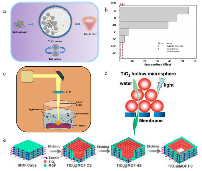
Ball milling is a widely employed top-down approach for reducing bulk TiO2 into nanosized particles,thereby increasing its surface area and enhancing the availability of active sites for photocatalytic reactions (Fig.2a). Additionally,this process induces surface oxidation,leading to the formation of a dense Ti oxide layer that limits oxygen penetration,effectively slowing further oxidation and improving the material’s stability. Notably,ball milling is a simple,cost-effective,and environmentally friendly technique. Compared with the direct mixing of Cu2O and TiO2,ball milling facilitates a more intimate contact between the two components,thereby maximizing H2 generation. However,excessive milling time and speed can significantly reduce the H2 production rate,highlighting the importance of optimizing these parameters (Fig.2b[45].
图2 TiO2基光催化剂的自上而下合成示意图:(a) 球磨示意图[28];(b) 标准化H2生产效应的帕累托图[45];(c) 激光烧蚀示意图[28];(d) 化学刻蚀的微观示意图[46];(e) 单分散TiO2@MOF FS的化学刻蚀合成示意图[47]

Fig.2 The top-down synthesis diagram of TiO2-based photocatalysts. (a) Ball milling schematic diagram. Reproduced with permission[28]. Copyright 2022,Elsevier. (b) Pareto diagram of standardized H2 production effect. Reproduced with permission[45]. Copyright 2022,Elsevier. (c) Laser ablation schematic diagram. Reproduced with permission[28]. Copyright 2022,Elsevier. (d) Microscopic schematic of chemical etching. Reproduced with permission[46]. Copyright 2008,ACS. (e) The schematic diagram of the chemical etching synthesis of monodisperse TiO2@MOF FS. Reproduced with permission[47]. Copyright 2020,Elsevier

In another study,Pd clusters supported on TiO2 were synthesized via ball milling[29]. Compared with samples prepared using conventional wet chemical methods,the Pd/TiO2-BM photocatalyst exhibited a substantially enhanced photocatalytic H2 production rate. The predominant Pd species generated through ball milling were in the metallic state,which promoted the effective separation of photogenerated electron-hole pairs. Under UV irradiation,a unique interaction between Pd clusters and TiO2 was observed,playing a critical role in stabilizing the photocatalytic reaction. Importantly,the ball milling technique enables the formation of stable metal clusters on oxide supports without requiring organic ligands for active site stabilization. Thus,compared with traditional synthesis routes,ball milling represents a viable and effective alternative for fabricating visible-light-active composite photocatalysts[29].

3.1.2 Laser ablation

Laser ablation is an effective technique for fabricating TiO2 nanostructures by irradiating bulk material with high-energy laser pulses,allowing precise control over nanoparticle size and morphology (Fig.2c). This method can be categorized into two main approaches:laser irradiation of conventional TiO2 powder dispersed in liquid,which results in partial oxygen loss,and pulsed laser ablation of a bulk metallic Ti target in liquid[32].
In recent years,pulsed laser ablation in liquid (PLAL) has gained increasing attention for synthesizing a variety of catalysts,including those for photocatalytic H2 production. Studies on TiO2 synthesis via PLAL have examined key ablation processes,including the physical and chemical transformations occurring in the plasma cloud,target surface,and surrounding solution. Using PLAL,researchers have successfully synthesized and optimized dark TiO2 for the photocatalytic H2 evolution reaction (HER)[32]. Notably,dark TiO2 exhibits strong absorption across the entire visible light spectrum and demonstrates enhanced photocatalytic efficiency. The highest activity was observed in samples annealed at 400 ℃,characterized by narrowly dispersed TiO2 with defective anatase crystals. Furthermore,modification with low concentrations of Pt further enhanced photocatalytic performance,increasing the H2 evolution rate by a factor of five. This enhancement was attributed to the increased photogenerated carrier density and reduced electron transfer resistance,indicating that Pt incorporation facilitates more efficient charge carrier dynamics.

3.1.3 Chemical etching

Chemical etching employs acids or other chemical agents to selectively remove material from bulk TiO2,generating nanostructured surfaces that enhance light absorption and reaction kinetics (Fig.2d,e[46-47]. This method is particularly effective for improving photocatalytic performance by increasing surface roughness and active sites. A novel acid-etched CFA/TiO2 nanocomposite was successfully synthesized using HCl etching and the sol-gel method,with CFA serving as the raw material[35]. The photocatalytic degradation efficiency of the acid-treated CFA/TiO2 nanocomposite was significantly higher than that of the untreated CFA/TiO2. HCl etching increased the surface roughness of CFA,allowing UV light to undergo multiple scattering within the sample,thereby enhancing photocatalytic efficiency. The combination of low cost and high degradation efficiency makes CFA a promising support material for TiO2 nanoparticles (NPs),expanding its potential for high-value applications.
Recently,researchers utilized a honeycomb aluminum plate as a metal substrate for TiO2 powder deposition,aiming to facilitate the practical application of TiO2 photocatalysts in toluene oxidation. To enhance the stability of the TiO2 coating,surface etching was performed using TiCl4 as a binder[36]. Compared to anodic oxidation etching,acid etching of the metal substrate exhibited superior load stability and photocatalytic activity. These improvements were attributed to the increased surface roughness of the metal substrate and the strong chemical adsorption between TiO2 and TiCl4,leading to enhanced catalyst-substrate interactions.

3.2 Bottom-up synthesis

Bottom-up approaches construct TiO2 nanostructures from molecular precursors,enabling precise control over their morphology,composition,and structural properties. These methods facilitate the tailored design of TiO2-based photocatalysts,optimizing their performance for specific applications. Key bottom-up synthesis techniques include sol-gel synthesis,hydrothermal synthesis,CVD,and PVD,each offering distinct advantages in controlling crystallinity,porosity,and surface characteristics.

3.2.1 Sol-gel synthesis

Sol-gel synthesis is a widely used method for producing TiO2 NPs. This process involves the hydrolysis and condensation of Ti alkoxides to form a gel,which is subsequently heated to induce crystallization. However,high-temperature annealing,often required to complete crystallization,can lead to unintended phase transitions. Specifically,anatase and brookite,both metastable phases,tend to irreversibly transform into rutile under prolonged thermal treatment[37]. Additionally,extended high-temperature exposure may cause the collapse of porous structures and tunnels,reducing the material’s surface area and catalytic efficiency[48]. Another critical challenge is uncontrolled nanoparticle aggregation,which can diminish the photocatalytic performance by reducing the available active sites. To mitigate this,surfactants are commonly employed as surface-directing or capping agents,reducing surface tension and enhancing solubility to prevent particle agglomeration[49].
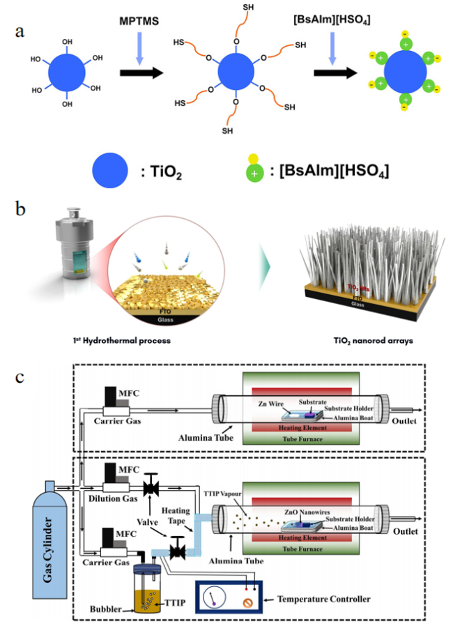
Ionic liquids (ILs) have emerged as effective soft templates for the controlled synthesis of TiO2-based photocatalysts due to their broad liquid temperature range,high thermal stability,and solubility in both organic and inorganic compounds. More importantly,their self-assembly properties facilitate the design of well-ordered nanostructures. For instance,Choi et al.[50] synthesized mesoporous nano-TiO2 by hydrolyzing tetraisopropyl titanate (TTIP) in 1-butyl-3-methylimidazolium hexafluorophosphate ([Bmim][PF6]) at room temperature. The resulting TiO2 nanocrystals exhibited excellent crystallinity and thermal stability,maintaining their phase composition even after exposure to 800 °C. The IL-assisted sol-gel method enables the synthesis of nano-TiO2 at relatively low temperatures by leveraging the self-assembly properties of ILs to guide mesoporous structure formation and control crystal growth (Fig.3a). Additionally,ILs enhance the thermal stability of anatase and inhibit its transition to rutile during heat treatment. This stabilization effect is primarily attributed to the π-π stacking interactions of the imidazole ring,which facilitate the polycondensation and crystallization of TiO2 nuclei,thereby improving phase stability and structural integrity.
图3 TiO2基光催化剂自下而上合成示意图:(a) IL-TiO2的分步合成过程示意图[37];(b) TiO2纳米棒阵列合成的水热过程示意图[51];(c) CVD法制ZnO纳米线和ZnO-TiO2核壳纳米线异质结构[41]

Fig.3 The bottom-up synthesis diagram of TiO2-based photocatalysts. (a) Illustration of the stepwise synthetic procedure of IL-TiO2. Reproduced with permission[37]. Copyright 2020,Springer Nature. (b) Schematics showing the overall hydrothermal procedure of the TiO2 nanorod arrays synthesis. Reproduced with permission[51]. Copyright 2021,Elsevier. (c) CVD method for the creation of ZnO nanowires and ZnO-TiO2 core-shell nanowires heterostructure. Reproduced with permission[41]. Copyright 2023,Elsevier

3.2.2 Hydrothermal synthesis

The hydrothermal method utilizes high-temperature and high-pressure conditions to facilitate the formation of TiO2 nanostructures. This approach is relatively simple,requiring fewer preparation steps,and is advantageous due to its environmental friendliness,low cost,and high tunability. It enables the synthesis of well-defined nanostructures with controlled morphologies,such as nanorods,nanotubes (NTs),and hierarchical structures (Fig.3b[51]. These structural features increase the surface area of the catalyst,enhance light absorption efficiency,and improve charge carrier extraction[52]. For instance,TiO2 photoanodes synthesized via the hydrothermal method exhibit enhanced charge transport performance due to the formation of highly crystalline structures and the suppression of electron-hole recombination.
The hydrothermal synthesis process typically involves dissolving a Ti precursor,such as TiCl4,in a solvent and subjecting the solution to high temperature and pressure within a sealed container. These conditions enable precise control over the size,morphology,and crystal structure of the resulting TiO2 NPs[51]. Despite its advantages,the hydrothermal method also presents certain limitations,including scalability and reproducibility challenges,relatively low crystallinity in some cases,and the tendency for particle aggregation,which can reduce the photocatalytic efficiency[41].

3.2.3 CVD

CVD is a gas-phase synthesis method that involves the decomposition of volatile precursors onto a substrate to form a thin film of TiO2. This technique is commonly used to create uniform,high-quality coatings of TiO2 on various surfaces. Moreover,the precise deposition of TiO2 films during the preparation of photoanodes can improve charge transport and reduce recombination loss,thereby improving photoelectrochemical (PEC) performance[53]. The doping technology in the CVD growth process can control the doping concentration and design the band gap,thereby enhancing light absorption in a wider solar spectrum. In addition,CVD promotes the growth of complex nanostructures with a high aspect ratio and large surface area,promoting light absorption and efficient charge carrier extraction,thereby improving PEC efficiency. The ZnO nanowires and ZnO-TiO2 core-shell nanowires developed by Jeong et al.[54] can precisely control the thickness of the shell (Fig.3c[41]. However,CVD still has some limitations. One limitation is the high cost and complexity of the equipment required for CVD synthesis,and the challenge of preparing high-quality films. In addition,the use of toxic and harmful precursor gases requires careful treatment and safety measures.

3.2.4 PVD

PVD is a process in which the solid is converted from a condensed state to a gas phase and then condensed into a film[55],which can be used to produce high-quality TiO2 films. Advanced PVD technology can provide precise control of the surface morphology of TiO2 photoanodes,allowing the generation of nanostructures or textured surfaces,thereby increasing active sites and improving light absorption efficiency[56]. In addition,the composition of TiO2 thin films can be controlled by adjusting the deposition parameters and material selection so that the band gap engineering can expand the absorption range of solar radiation and improve the utilization of solar energy.
Sputtering is a variant of PVD technology[41]. TiO2 films can be rapidly deposited on different substrates by RF magnetron sputtering. This method allows tailoring film properties in an economical,efficient and scalable manner,providing new possibilities for the production of advanced high-performance materials that are in direct contact with the final carrier. However,due to the high vacuum environment and temperature requirements of PVD,as well as the complex system architecture,it has a higher cost and more difficult operation than CVD. This greatly reduces the scalability of the PVD process.

4 Design strategies of TiO2-based photocatalysts for H2 production

4.1 Elemental doping

4.1.1 Doping with metal elements

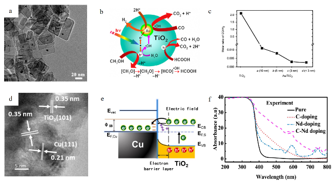
Doping TiO2 with metal elements is one of the most effective strategies for narrowing its band gap and enhancing its visible light absorption. Precious metals such as Pt and Au can serve as co-catalysts to facilitate charge separation. Pt and Au are more stable and durable than base metals,providing high activity for prolonging photocatalytic function[57]. In an experiment,TiO2 NSs with exposed (001) facets were prepared in a Ti(OC4H94-HF-H2O mixed solution. Then,under the irradiation of a xenon lamp,Pt NPs were deposited on TiO2 NSs by the photochemical reduction method to obtain Pt/TiO2 nano-photocatalyst (Fig.4a[58]. The researchers found that when the Pt/TiO2 nanophotocatalyst was placed in an ethanol aqueous solution,the Pt loaded on the TiO2 NSs increased the photocatalytic H2 production rate,and even 2 wt% deposited Pt showed the highest catalytic activity. However,the disadvantage of Pt is that it is rare and too expensive. In addition,when methanol is decomposed during the photocatalytic process on the Pt/TiO2 catalyst,CO,H2 and other gases are produced. CO with a concentration of about 2.7 vol% was observed in H2. This is a problem that needs to be solved because a very small amount of CO will poison the catalyst and thus affect the catalytic activity.
图4 掺杂TiO2基光催化剂的微观结构、性能及示意图:(a) Pt/TiO2纳米片(NSs)的透射电镜(TEM)图像[60];(b) Au/TiO2催化剂的光催化反应图;(c) Au/Pt/TiO2催化剂光催化重整的CO选择性[61];(d) Cu-TiO2复合物的高分辨透射电镜(HRTEM)照片;(e) TiO2-Cu-2.5%的能带图和电子转移路径[62];(f) C、Nd和C+Nd掺杂TiO2的光吸收谱[63]

Fig.4 Microscopic,performance and schematic diagram of doped TiO2-based photocatalysts. (a) Transmission electron microscopy (TEM) image of Pt/TiO2 nanosheets (NSs). Reproduced with permission[60]. Copyright 2010,ACS. (b) Photocatalytic reaction diagram of Au/TiO2 catalyst. (c) CO selectivity in photocatalytic reforming of Au/Pt/TiO2 catalyst. Reproduced with permission[61]. Copyright 2008,Elsevier. (d) High-resolution TEM (HRTEM) image of Cu-TiO2 complex. (e) Energy band diagram and proposed electron transfer path of TiO2-Cu-2.5%. Reproduced with permission[62]. Copyright 2019,Elsevier. (f) Optical absorption spectra of C,Nd and C+Nd doped TiO2. Reproduced with permission[63]. Copyright 2022,Springer Nature

Au can also be used as a doping component on TiO2 semiconductors to prepare photocatalysts. Researchers used an ultralow concentration of CO to produce H2 by photocatalytic decomposition of methanol on an Au/TiO2 catalyst (Fig.4b[58]. It is found that the H2 production rate is significantly improved when the size of Au particles is reduced from 10 nm to less than 3 nm. In addition,with the decrease of Au particle size,the absorption of CO will decrease (Fig.4c). This is because when the intermediate product formic acid is decomposed to form methanol,it mainly produces CO. When the Au particle size decreases,the decomposition of formic acid stops,and the main product CO stops producing;only H2 and CO2 are produced as by-products. However,Bamwenda et al.[59] compared the hydrogen production activity of Au/TiO2 and Pt/TiO2 catalysts. The hydrogen production activity of the Pt sample was 30% higher than that of the Au sample. This is because Au is highly dependent on the preparation method compared to Pt. When the calcination temperature increases from 573 K,the hydrogen production of the Au sample is lower than that of the Pt sample.
Non-precious metal doping offers a cost-effective and environmentally benign strategy to enhance the photocatalytic properties of TiO2. Such dopants not only suppress the recombination of photogenerated charge carriers—thereby improving photocatalytic and PEC performance—but also contribute to band gap narrowing,which facilitates broader visible-light absorption[64]. In addition to their low cost and chemical stability,non-precious metal elements often introduce defect states or modulate the electronic structure of TiO2,enabling more efficient utilization of solar energy. For example,Cu as a catalyst improves charge separation and enhances the photocatalytic activity of TiO2 for H2 production. Under visible light irradiation,Cu-TiO2 exhibits an H2 evolution rate comparable to that of Au-TiO2[65]. This can be attributed to the plasma surface effect of Cu-NPs and Au-NPs. Since the direct excitation of TiO2 requires UV light,the activity of these TiO2 materials can be achieved by the excitation of Cu and Au plasmon bands. In another experiment,Cu-doped mesoporous TiO2 hybrid nanostructured composites were used for photocatalytic H2 production from methanol-containing water under 300 W artificial light irradiation (Fig.4d[66]. The co-catalyst properties of Cu metal and the Schottky junction formed between Cu metal and TiO2 n-type semiconductor play an important role in the separation and transmission of electron-hole pairs,the prevention of recombination and the improvement of HER potential (Fig.4e). Among them,the H2 evolution potential of TiO2-Cu-2.5% is 23 times that of a pure TiO2 catalyst. According to X-ray photoelectron spectroscopy (XPS) analysis,it can be inferred that the doping of Cu on TiO2 follows interstitial doping. The higher photocurrent density of the TiO2-Cu-2.5% catalyst indicates that Cu particles are beneficial to the separation and transport of photogenerated electron-hole pairs. Electrochemical impedance spectra (EIS) confirmed that the TiO2-Cu-2.5% photocatalyst followed a small semi-circular pattern,indicating that the material had a medium-low charge transfer resistance and effective interface charge transfer potential. Similarly,the relatively low PL intensity of the TiO2-Cu-2.5% catalyst indicates that the material has greater potential to inhibit electron and hole recombination. Therefore,based on the aforementioned optical properties,Cu-doped mesoporous TiO2 hybrid nanostructured composites can provide a high HER rate. However,the performance of a single non-precious metal cocatalyst is quite limited and exhibits poor long-term stability due to its easy oxidation. The proper combination of non-precious metals can optimize the overall performance of metals and may exceed the durability of precious metals[67].
Precious metals like Pt and Au have high doping efficiency but high cost,and need to solve the problem of CO by-products. The doping of non-precious metal Cu is economical and environmentally friendly,and the performance is close to that of precious metal,which is a more promising alternative. Future research can focus on optimizing metal particle size,loading and doping methods to balance activity,stability and cost.

4.1.2 Doping with non-metal elements

The use of non-metal-doped TiO2 can reduce its band gap,which is an effective way to enhance its visible light absorption capacity and H2 evolution ability. The addition of non-metallic dopants to the TiO2 matrix may cause structural defects in the material,form impurity energy levels,narrow the band gap,and help overcome the shortcomings of common carrier capture and thermal instability of metal NPs[68]. N is one of the most studied non-metallic dopants because it has a similar atomic size to O,forming a metastable energy state,and there is a considerable overlap between N2p and O2p states,resulting in a narrowing of the band gap and the smooth excitation of electrons between the valence band and the conduction band[69]. The results show that compared with pure TiO2,the optical properties,valence band characteristics,and band position of N-doped TiO2 samples have changed. Moreover,compared with pure TiO2,N-doped TiO2 samples show charge separation and an increase in charge carrier density.
C doping is also an effective method to modify TiO2. It has been reported that C can not only reduce the band gap by forming an intermediate energy level in the band gap of TiO2 but also promote the adsorption of organic matter and the transport of photogenerated carriers inside TiO2[70]. Studies have shown that the addition of C and Nd dopants can increase the light absorption intensity of TiO2 and broaden the light absorption range to visible light[68]. The absorption spectrum of pure TiO2 is not extended to the visible light region,but the absorption range of TiO2 is extended to the visible light region by C doping and C,Nd co-doping,which improves the photocatalytic efficiency of TiO2 Fig.4f). In another study,the photodegradation of 4-chlorophenol under UV and visible light showed that C-doped TiO2 exhibited better catalytic activity under visible light because the C-containing compounds on the surface of the catalyst were removed under UV light,which weakened the catalytic synergy between the C-containing substances on the surface of the catalyst and the crystalline C[70]. An appropriate amount of dopant is very important to improve the catalytic activity of TiO2. This is because,on the one hand,excessive dopants will lead to a large number of defects in the TiO2 lattice,inhibiting the separation of photogenerated carriers;on the other hand,too many carbides will be formed on the surface of TiO2,which will affect the light absorption,hide the active sites and reduce the photocatalytic activity.
Non-metal elements N and C doping is an effective means to regulate the band structure of TiO2,which can significantly improve the visible light response and catalytic activity. However,it is necessary to optimize the doping concentration and method to balance the band gap narrowing and defect suppression to avoid side effects. In the future,more non-metal element combinations can be explored to further optimize the photocatalytic performance of TiO2.

4.2 Morphology engineering

Morphology engineering is an effective way to improve the photocatalytic water-splitting performance of TiO2. Researchers can use morphology engineering to modify the size,shape and surface area of the material to enhance the charge transfer and light absorption characteristics of TiO2. The nanostructures of TiO2-based photocatalysts can usually be divided into four dimensions:zero-dimensional (OD) nanostars and quantum dots,NPs,one-dimensional (1D) nanowires,NTs,nanorods,two-dimensional (2D) NSs,three-dimensional (3D) nanoflowers,nanospheres,and nanotetrahedra. An important progress in TiO2 semiconductors is the direct growth of single crystals on conductive substrates,which can reduce the recombination of charge carriers and thus increase the rate of H2 evolution[41,69,71].
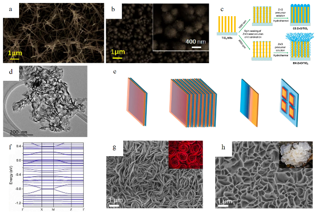
1D nanostructures can provide a “high-speed” path along the longitudinal direction for single crystal nanostructures and shorten the charge diffusion length[72]. Zhou et al.[73] studied two unique ZnO/TiO2 structures and prepared an open bird’s nest structure (BN ZnO/TiO2) and a closed core-shell structure (CS ZnO/TiO2) by controlling the spin coating speed of the ZnO seed solution (Fig.5a,b[41]. The cross-linked ZnO nanowires are uniformly dispersed on the TiO2 nanorods of BN ZnO/TiO2,while the ZnO nanowires on the TiO2 nanorods of CS ZnO/TiO2 are close to each other (Fig.5c). The BN ZnO/TiO2 photoanode resulted in a significant decrease in the onset potential and a significant increase in the photocurrent density,and the BN ZnO/TiO2 exhibited the highest PEC performance,showing a smaller Tafel slope and a higher surface charge injection efficiency (ηsurface) value. BN ZnO/TiO2 has a higher ηsurface value than CS ZnO/TiO2,indicating that the bird’s nest morphology is more conducive to promoting hole transfer.
图5 经过形貌工程后的TiO2基光催化剂的显微成像:(a,b) BN ZnO/TiO2和CS ZnO/TiO2的扫描电镜(SEM)图像;(c) 示意图[41];(d) 2D-TiO2/g-C3N4的TEM图像[71];(e) 典型的2D/2D异质结构示意图[71];(f) 2D-TiO2/g-C3N4纳米复合材料的能带结构[74];(g,h) TiO2/ZnIn2S4和TiO2/Cd:ZnIn2S4的SEM图[75]

Fig.5 Microscopic imaging of TiO2-based photocatalysts after morphology engineering. (a,b) Scanning electron microscopy (SEM) images of BN ZnO/TiO2 and CS ZnO/TiO2. (c) Schematic diagram. Reproduced with permission[41]. Copyright 2023,Elsevier. (d) TEM image of 2D-TiO2/g-C3N4. Reproduced with permission[71]. Copyright 2024,Elsevier. (e) Schematic illustration of typical 2D/2D heterostructures[71]. Copyright 2024,Elsevier. (f) Band structure of 2D-TiO2/g-C3N4 nanocomposites. Reproduced with permission[74]. Copyright 2020,Elsevier. (g,h) SEM images of TiO2/ZnIn2S4 and TiO2/Cd:ZnIn2S4. Reproduced with permission[75]. Copyright 2022,Elsevier.

2D nanostructured films can expose highly reactive crystal planes and shorten the charge diffusion length[72]. 2D/2D heterostructures can be formed through various contact interfaces,such as face-to-face or cross-sectional alignment[71]. In order to optimize the contact area in the 2D/2D heterojunction,two or more materials can be stacked to establish face-to-face interface contact. The coupling pressure between the 2D/2D interfaces,characterized by weak van der Waals interactions between layers,can produce heterostructures. For example,Zhang et al.[74] successfully prepared 2D-2D TiO2/g-C3N4 heterostructures with strong interface coupling by an in situ growth strategy (Fig.5d,e). This process creates a strong chemical connection between TiO2 NSs and g-C3N4 NSs,resulting in enhanced chemical interface interaction. The charge transfer occurs at the entire interface through the N—O—Ti bond,resulting in a significant increase in electrons in the Ti atom and a loss of electrons in the N atom. Some band gap states caused by the close interaction of heterostructures are formed in the band structure of 2D-TiO2/g-C3N4Fig.5f). Therefore,compared with the single 2D-TiO2 monolayer,the visible light absorption of the heterostructure has been greatly improved. This is because the strong coupling of the 2D-2D heterostructure induced significant charge transfer and gap states exhibiting an extraordinary interface coupling state,which significantly enhances the interface charge transfer behavior,thereby greatly improving the electron unsaturation and visible light response. However,2D/2D heterojunctions are prone to restacking issues,which affect the interface quality of heterojunctions[71]. This will lead to a decrease in carrier mobility and the weakening of interlayer coupling in heterojunctions. This is a key issue that needs to be paid attention to when preparing 2D/2D heterojunctions.
3D nanostructures have unique properties,such as light guidance,capture and scattering,to improve PEC efficiency[72]. The researchers synthesized rose-like ZnIn2S4 and tremella-like Cd:ZnIn2S4 on the pre-prepared TiO2 NTs (Fig.5g,h[41]. With the increase of Cd content in Cd:ZnIn2S4,thicker petals and more voids were observed,indicating that Cd2+ ions partially replaced Zn2+ ions in the crystal structure of ZnIn2S4,which was due to the larger radius of Cd2+ ions.
Morphology engineering is applied to optimize the charge transport and light absorption properties of TiO2 by adjusting its size,shape and surface area,thereby improving the performance of photocatalytic hydrogen production. The nanostructures of TiO2-based photocatalysts can usually be divided into four dimensions:OD,1D,2D and 3D. The OD design strategy is to synthesize ultra-small NPs by solvothermal or colloidal chemical methods,narrow the band gap by quantum effects to control the size,and coat or load co-catalysts to suppress carrier recombination. The 1D design strategy is to vertically grow single-crystal nanowires on a conductive substrate to reduce grain boundary charge loss and to form a core-shell or branch structure with other 1D materials to enhance interfacial charge separation. The 2D design strategy is to regulate the synthesis conditions to preferentially expose active crystal surfaces,such as (001) and to form a chemical bonding interface through in-situ growth (such as TiO2/g-C3N4) to avoid poor contact caused by physical stacking. The 3D design strategy is to construct a macroporous-mesoporous composite structure by a template method to enhance light scattering and reactant diffusion,and to regulate the morphology by element doping. For example,Cd2+ doped ZnIn2S4 changes the petal thickness and porosity to optimize the light absorption path. In the future,the development of low-cost and scalable morphology control methods can be studied to promote practical applications.

4.3 Composite

4.3.1 Graphene/TiO2 composite

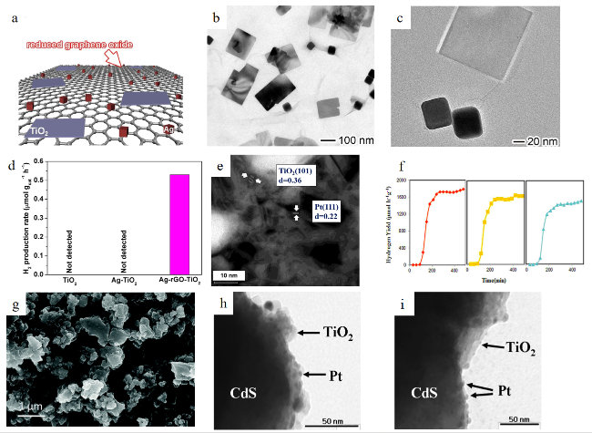
Graphene is the first 2D material with outstanding advantages,such as a high specific surface area and good electron transfer ability[76],which minimizes the reconsolidation of photogenerated charges and improves the photocatalytic yield of the material. Graphene has no band gap,while TiO2 has a larger band gap. Therefore,the combination of graphene and TiO2 is considered to be the perfect combination for photocatalytic applications[77]. The simultaneous doping of metal ions and graphene into TiO2 is a continuous research topic to improve photocatalytic H2 production activity. Lang et al.[78] prepared Ag-rGO-TiO2 composites by depositing Ag nanocubes and TiO2 nanolayers on the surface of reduced graphene oxide (Fig.6a~c). In addition,the author also prepared Ag-TiO2 as a comparison. Under visible light irradiation,the H2 production rate per unit mass of Ag-rGO-TiO2 was 0.53 μmol/(g·h) in methanol aqueous solution,while Ag-TiO2 and TiO2 did not show photocatalytic activity (Fig.6d). This enhanced activity is considered to be the performance of rGO as a conductive bridge to transfer electrons from Ag to TiO2. In addition,the Schottky barrier formed on the surface of rGO-TiO2 enhances the diffusion of hot electrons from rGO to TiO2. For the Ag-TiO2 structure,the hot electrons and holes are recombined due to the absence of a barrier.
图6 TiO2基复合光催化剂微观结构、性能及示意图:(a) Ag-rGO-TiO2杂化结构示意图;(b,c) Ag-rGO-TiO2杂化结构的TEM图像;(d) 在可见光照射下,纯TiO2纳米片、Ag-TiO2和Ag-rGO-TiO2杂化结构的平均光催化产氢速率[78];(e) 0.5% Pt/TiO2-ZnO的TEM图像;(f) Pt/TiO2-ZnO光催化剂重复使用后的产氢速率[79];(g) Cu/CuO/TiO2杂化纳米复合材料的FESEM图像[80];(h,i) 湿浸渍法(WI)和化学还原法(CR)制备的Pt修饰CdS/TiO2复合光催化剂的TEM照片[81]

Fig.6 Microscopic,performance and schematic diagram of TiO2-based composite photocatalysts. (a) The schematic diagram of the Ag-rGO-TiO2 hybrid structure. (b,c) TEM images of the Ag-rGO-TiO2 hybrid structure. (d) The average photocatalytic H2 production rate of bare TiO2 NSs,Ag-TiO2 and Ag-rGO-TiO2 hybrid structures under visible light irradiation. Reproduced with permission[78]. Copyright 2018,Elsevier. (e) TEM image of 0.5% Pt/TiO2-ZnO. (f) H2 production rate of Pt/TiO2-ZnO photocatalyst after repeated use. Reproduced with permission[79]. Copyright 2017,Elsevier. (g) FESEM image of Cu/CuO/TiO2 hybrid nanocomposite. Reproduced with permission[80]. Copyright 2016,RSC. (h,i) TEM images of Pt-modified CdS/TiO2 composite photocatalysts by wet impregnation (WI) and chemical reduction (CR). Reproduced with permission[81]. Copyright 2008,ACS

The co-doping of metal Ag and graphene can synergistically enhance the photocatalytic activity of TiO2,in which the electron conduction and interface barrier regulation of graphene are crucial. The future direction is to explore other metal-graphene composite systems and optimize the interface structure to further improve the charge separation efficiency.

4.3.2 Metal oxide/TiO2 composite

Metal oxide has excellent chemical stability and corrosion resistance,and the formation of complexes with TiO2 can prolong the life of the catalyst[82]. Moreover,metal oxide has the characteristics of enhancing photocatalytic activity,which can expand the light response range of the TiO2 photocatalyst and inhibit electron-hole recombination. Encouragingly,metal oxide/TiO2 is a TiO2-based composite with superior HER performance. Taking ZnO as an example,it has the advantages of high photochemical stability,a wide band gap,good photosensitivity and non-toxicity,and has been widely studied in photocatalytic applications. Therefore,the composite of ZnO and TiO2 is used in the field of photocatalytic HER[77]. For example,Xie et al.[79] mixed TiO2 and ZnO in different proportions before depositing Pt as a co-catalyst for H2 evolution (Fig.6e). The results showed that 0.5% Pt/TiO2-ZnO exhibited the best photocatalytic H2 production performance,and the H2 production rate per unit mass was 2150 μmol/(h·g) under visible light irradiation. The H2 production rates per unit mass of TiO2 and ZnO are 68 and 3.0 μmol/(h·g),respectively. In addition,the durability of the catalyst was tested for H2 production. Compared with the first-day test,the H2 production rate on the 7th and 14th days was only reduced by 12% and 23%,respectively (Fig.6f).
A promising method for preparing metal oxide/TiO2 composites is to use metal-organic frameworks (MOFs) as precursors. MOFs,known as the first members of the cage-like porous material family,are constructed by the combination of metal clusters and organic compounds. MOFs have outstanding properties such as high porosity,large surface area and adjustable chemical structure,and have many uses,including being used as sacrificial templates to prepare metal oxide/TiO2 composites[77]. Mondal and Pal[80] used Cu-based MOF as a sacrificial template to prepare composites. The yield of the optimized Cu/CuO/TiO2 hybrid nanocomposites under sunlight irradiation is much better than that of the traditional CuO/TiO2 hybrid system,which is due to the formation of a small heterojunction and the loading of Cu into the TiO2 matrix (Fig.6g). Dekrafft et al.[83] prepared a Fe2O3@TiO2 core-shell structure using Fe-based MOF and then deposited Pt on its surface for photocatalytic H2 production. Compared with Fe2O3,TiO2 and their mixtures,the catalyst showed a faster H2 production rate.
Metal oxide/TiO2 composites have high activity and stability,and the MOF template method provides a new way for the synthesis of composite materials. In the future,it is necessary to solve the cost problem of complex preparation processes and explore more efficient and inexpensive metal oxide combinations.

4.3.3 Sulfide/TiO2 composite

The direct interaction between sulfide and TiO2 has a short band gap and is easy to use in visible light[84]. Their good response to sunlight is due to the presence of conduction bands at high positions compared to metal oxides. In addition,metal sulfides have good adsorption capacity,and this effective adsorption reduces their oxidation capacity,making them poor reagents in water decomposition. Therefore,these systems require a certain sacrificial agent to produce H2 under the condition of photocatalytic reduction of water.
The band gap of CdS is 2.42 eV,and the smaller band gap makes it have a high application value by photocatalytic decomposition of water under visible light. However,it has a faster electron-hole pair recombination rate,which makes its photocatalytic efficiency lower. On the contrary,TiO2 has good electron-hole pair recombination,making it a more effective photocatalyst,but its band gap is 3.42 eV,which limits its application in the visible region. Therefore,researchers began to focus on the study of CdS/TiO2 composites to overcome the obstacles of photocatalytic decomposition of TiO2 and CdS to produce H2[85]. Researchers have used different methods such as WI,CR,and photo deposition (PD) to platinum the CdS/TiO2 composite photocatalyst to produce H2 in the visible light region (Fig.6h,i[86]. To this end,the metal Pt is implanted on the composite material. Because of the extra high and low states generated by the WI,CR and PD processes,Pt becomes more important so that the efficiency of the CdS/TiO2 composite photocatalyst is higher. On the other hand,the photocatalysts of WI and PD are composed of electron-deficient Pt. In WI,the formation of Pt-Ti fills this defect because the recombination of electron-hole pairs takes a longer time for two electron-deficient photocatalysts,resulting in higher efficiency of water splitting for H2 production. In another experiment,the researchers used titanate NTs to realize the variable diameter systematization of CdS/TiO2 composites through a simple ion change and vulcanization process at medium temperature[86]. The use of this composite as a photocatalyst increased the yield of H2. In this process,an almost 43.4% yield was obtained in the visible light region with a wavelength of about 525 nm. This may be due to the synergistic effect between TiO2 NTs and CdS NPs,as well as the uniform distribution and quantum effect of CdS particles.
After the combination of sulfide CdS and TiO2,the visible light hydrogen production efficiency is significantly improved by matching the energy band structure. Pt loading (such as the electron-deficient Pt-Ti bond formed by the WI/PD method) and nanostructure control (such as TiO2 NTs and CdS NPs composite) can optimize charge separation and transport,and the hydrogen production rate is increased. In the future,it is necessary to combine new sulfides,atomic interface engineering and in situ characterization techniques to promote the development of efficient,stable and low-cost photocatalytic systems.

5 Advanced characterization techniques for TiO2-based photocatalysts

5.1 X-ray diffraction (XRD)

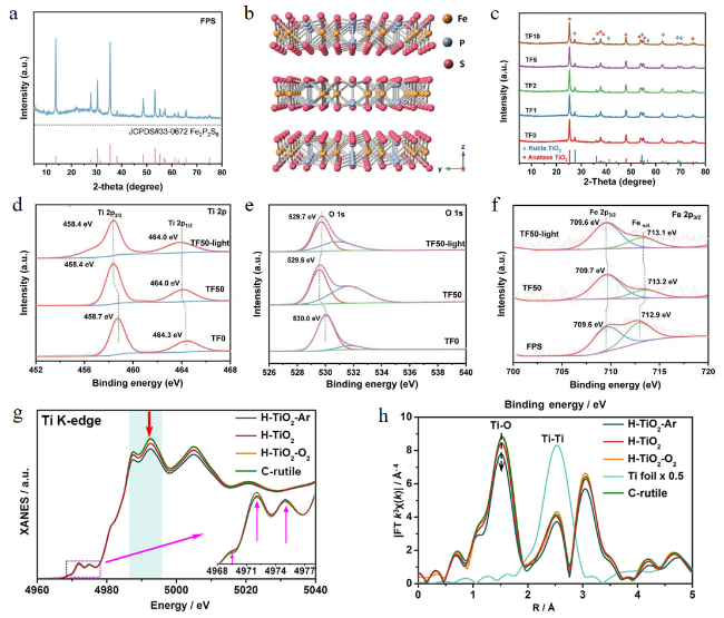
XRD is a characterization technique based on crystal atoms that diffract an incident X-ray beam in many specific directions. XRD can be used to identify the crystal structure and phase composition of TiO2,which can reveal the relationship between the structure and photocatalytic performance of TiO2-based photocatalysts[87]. Bulk FPS was exfoliated into 2D NSs (FPS NSs) via grinding-assisted ultrasonication and centrifugation in ethanol[88]. XRD analysis confirmed the monoclinic phase of FPS,consistent with its layered crystal structure. In a typical FPS unit cell,one Fe atom is connected to six adjacent S atoms. The P atom is connected to one P atom and three S atoms (Fig.7a,b). Subsequently,TiO2 NPs were anchored onto FPS NSs by grinding,using varying volumes (1,2,5,10 mL) of FPS suspension with 0.05 g TiO2,denoted as TF1,TF2,TF5,and TF10,respectively;pristine TiO2 was labeled TF0. XRD patterns of all TF samples revealed both rutile and anatase TiO2 phases (Fig.7c),while FPS diffraction peaks were absent,likely due to their low loading content.
图7 TiO2基光催化剂的X射线表征技术:(a) FPS纳米片的XRD图谱;(b) 单斜FPS沿[100]方向的侧视原子结构;(c) TF0、TF1、TF2、TF5、TF10的XRD图谱;(d~f) 无光照和有光照的TF0和TF50的Ti 2p和O 1s的高分辨XPS谱以及无光照和有光照的FPS 纳米片的Fe 2p3/2的高分辨XPS谱[88];(g,h) Ti K边的X射线吸收近边结构(XANES)谱和扩展X射线吸收精细结构的k3加权傅里叶变换(FT-EXAFS)谱[89]

Fig.7 X-ray-based characterization techniques for TiO2-based photocatalysts. (a) XRD pattern of FPS NSs. (b) The side-looking atomic structure of monoclinic FPS along the [100] direction. (c) XRD pattern of TF0,TF1,TF2,TF5 and TF10. (d~f) High-resolution XPS spectra of Ti 2p and O 1s for TF0 without light illumination and TF50 without/with light illumination and high-resolution XPS spectra of Fe 2p3/2 for FPS NSs without light illumination and TF50 without/with light illumination. Reproduced with permission[88]. Copyright 2022,Wiley. (g,h) X-ray absorption near edge structure (XANES) spectra of Ti K-edge and k3-weighted Fourier transform of extended X-ray absorption fine structure (FT-EXAFS) spectra. Reproduced with permission[89]. Copyright 2022,Elsevier.

In situ XRD,particularly when coupled with synchrotron radiation,has emerged as an indispensable tool for elucidating the crystallization dynamics of TiO2 under variable reaction environments. Its time-resolved and non-destructive nature enables real-time tracking of phase evolution,offering insights into the nucleation and growth mechanisms under hydrothermal or solvothermal conditions. In particular,in situ XRD facilitates the precise mapping of phase transitions. Beyond qualitative phase identification,in situ XRD enables semi-quantitative analysis of crystallinity,average grain size estimation,and particle size distribution profiling,thereby constructing detailed crystallization curves that capture kinetic profiles and thermodynamic stability windows. These insights are essential for guiding the rational design of TiO2-based photocatalysts with tailored phase compositions and defect architectures[87].

5.2 XPS

XPS serves as a powerful surface-sensitive technique for probing the elemental composition,oxidation states,and electronic interactions in TiO2-based photocatalysts[90]. Both ex situ and in situ XPS measurements provide valuable insights into charge redistribution and interfacial electronic structures in heterojunction systems. For instance,in FPS/TiO2 nanocomposites,the absence of Fe,P,and S signals in low-FPS-content samples underscores the detection limit of XPS,which was overcome by increasing the precursor concentration during TF50 synthesis[88]. Upon the formation of the heterojunction,characteristic core-level shifts were observed:the Ti 2p and O 1s peaks shifted toward lower binding energies (the Ti 2p peak of TF50 shifted from 464.0 to 458.4 eV),while the Fe 2p3/2,P 2p,and S 2p peaks exhibited positive shifts (the Fe 2p3/2 peak of TF50 shifted from 709.7 eV to 713.2 eV),collectively indicating electron transfer from FPS to TiO2Fig.7d~f). This electron redistribution suggests the establishment of a space charge region and a built-in electric field oriented from FPS to TiO2,driving the band bending upward in FPS and downward in TiO2 at the interface. Under photoirradiation,further binding energy shifts in O1s (toward higher energies from 529.6 to 529.7 eV) and Fe/P/S (toward lower energies,the Fe 2p3/2 peak of TF50 shifted from 709.7 to 709.6 eV) confirm photoinduced charge separation,with photogenerated holes accumulating on TiO2 and electrons on FPS. These observations provide compelling evidence of effective interfacial charge transfer and band alignment tuning,which is critical for enhancing photocatalytic efficiency.
While ex situ XPS has significantly advanced our understanding of static surface chemistry,the emerging application of in situ/operando XPS offers unparalleled opportunities to probe real-time electronic and chemical changes at photocatalyst interfaces under working conditions[90]. In the context of TiO2-based systems,in situ XPS enables direct monitoring of photoinduced charge redistribution,valence band edge shifts,and surface adsorbate dynamics during illumination or applied bias. This is particularly valuable for capturing transient oxidation states of dopants or co-catalysts. Moreover,the integration of in situ XPS with other spectroscopic modalities—such as ambient-pressure XPS (AP-XPS),time-resolved XPS (TR-XPS),and XPS-Raman hybrid setups—holds promise for correlating chemical shifts with lattice strain,local bonding environments,and photon-driven surface reactions. Such multi-dimensional insights are critical for decoding the interplay between defect states,space charge regions,and band-bending phenomena that dictate charge separation and recombination pathways.

5.3 X-ray absorption spectroscopy (XAS)

XAS serves as a powerful diagnostic tool for probing the local atomic and electronic environments of TiO2-based photocatalysts,particularly under operando or in situ photocatalytic conditions[90]. By offering element-specific sensitivity,XAS enables the direct observation of structure-function correlations,including dynamic changes in oxidation states and coordination geometries during light-driven water splitting. XAS comprises two key components:XANES,which provides insights into the oxidation states,coordination symmetry,and electronic transitions of Ti sites,and EXAFS,which reveals quantitative structural parameters such as bond lengths,coordination numbers,and local disorder. For TiO2-based systems,subtle shifts in the Ti K-edge or O K-edge XANES features can signal the formation of oxygen vacancies,under-coordinated Ti centers,or photoinduced valence fluctuations—all of which are strongly linked to enhanced photocatalytic activity[91].
Advanced XANES simulations and fitting approaches allow for the identification of defect-rich sites,asymmetric coordination,and lattice distortions by comparing experimental spectra with ab initio-generated references. These analyses are particularly valuable for studying heterostructured TiO2,doped systems,and MOF-derived frameworks,where the active centers deviate from the ideal anatase or rutile configurations[92]. When performed under real-time illumination and in reactive environments,XAS provides crucial mechanistic insight into how light absorption and subsequent charge dynamics translate into catalytic function. In a recent study performed on four samples of H-TiO2-Ar,H-TiO2,H-TiO2-O2, and C-rutile,Ti K edge XANES spectra of different samples were similar (it is about 4986 to 4995 eV),confirming a similar local structure environment (Fig.7g[89]. The front peak of Ti (4969.4,4972.0 and 4975.1 eV,the pink curve in Fig.7g) represents the 1s→3d and 1s→hybrid p-d transitions of octahedral symmetry. The intensity of H-TiO2 is slightly higher than that of C-rutile and H-TiO2-O2,indicating that the presence of Ti-H distorts the local structure. However,compared with H-TiO2,a stronger front peak appeared on the H-TiO2-Ar curve,indicating that the local structure was more distorted after Ar annealing. Compared with C-rutile,H-TiO2-O2 and H-TiO2,the white line intensity (light green range in Fig.7g) of H-TiO2-Ar decreased,and the adsorption edge moved to the low energy direction,indicating that the oxidation state of Ti decreased. This is due to the presence of Ti3+ and H-TiO2-Ar has a lower Ti valence. The FT-EXAFS spectrum shows a main peak at 1.50,which belongs to the Ti-O scattering path (Fig.7h). The intensity of the peak decreases in the order of C-rutile (about 8.9 Å),H-TiO2-O2 (about 8.8 Å),H-TiO2 (about 8.5 Å) and H-TiO2-Ar (about 7.5 Å),indicating that the O coordination number of the Ti center decreases.

5.4 TEM and SEM

TEM is an indispensable tool for resolving the nanoscale morphology,crystallinity,and defect structures of TiO2-based photocatalysts[87]. Beyond static imaging,HRTEM enables the direct visualization of lattice fringes and defect sites,revealing fine structural features that govern charge carrier dynamics. During the formation of TiO2 nanostructures via processes such as hydrothermal treatment,micro-arc oxidation,or ion implantation,TEM has been extensively used to monitor microstructural evolution,including phase transitions,nanocrystal coalescence,and facet rearrangement.
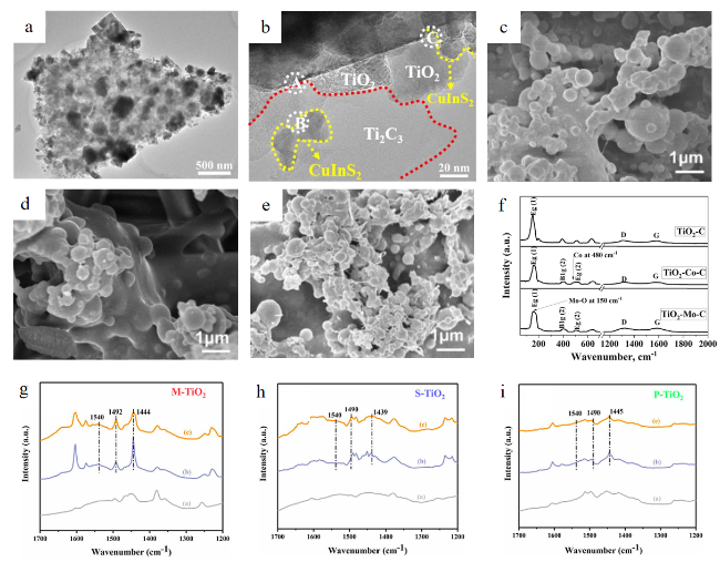
When coupled with electron energy loss spectroscopy (EELS),TEM provides spatially resolved information on elemental composition,oxidation states (e.g.,Ti3+ vs. Ti4+),and even bandgap variation at the nanoscale. This multimodal capability allows researchers to correlate local chemical environments with specific morphological features,thereby offering a holistic understanding of structure-activity relationships in TiO2 systems. In the context of modified or composite TiO2 materials,TEM also plays a key role in revealing heterojunction interfaces,dopant dispersion,and crystal domain coherence. Recent TEM studies have elucidated the morphological and interfacial architecture of Ti3C2 MXene-based TiO2/CIS composites[93]. Ti3C2 MXene exhibits a typical 2D layered morphology,while the Ti3C2@TiO2 (M@T) hybrid adopts a 2D/2D configuration. Upon incorporation of CIS NPs,the resulting M@T/CIS composite maintains a transparent layered structure decorated with finely dispersed CIS domains (Fig.8a,b). HRTEM and corresponding fast Fourier transform (FFT) analyses confirm the formation of heterojunctions between M and T in M@T,as well as well-defined interfaces among M,T,and CIS in the ternary system. The HRTEM images of M@T/CIS-20 composites recorded in different labeling regions were used to further reveal the existence of interface structure between Ti3C2,CuInS2 and TiO2. Obviously,the lattice spacing of 0.35,0.260 and 0.326 nm are attributed to the (101),(010) and (112) planes of TiO2,Ti3C2 and CuInS2,respectively,which confirms the formation of ternary Ti3C2 MXene@TiO2/CuInS2 heterojunction. These extended and intimate interfaces promote efficient charge separation and are key contributors to the enhanced photocatalytic activity observed.
图8 TiO2基光催化剂的TEM、SEM、拉曼和傅里叶变换红外(FTIR)光谱图像:(a,b) Ti3C2 MXene@TiO2/CuInS2 (M@T/CIS)的TEM图像[93];(c~e) TPU-2%光敏机理石墨烯/TiO2 (DTG)、TPU-4% DTG和TPU-6% DTG的SEM图[95];(f) TiO2-C、TiO2-Co-C和TiO2-Mo-C的拉曼光谱[96];(g~i) 吡啶在M-TiO2表面、S-TiO2表面和P-TiO2表面吸附的原位红外光谱[97]

Fig.8 TEM,SEM,Raman and Fourier transform infrared (FTIR) spectroscopy images of TiO2-based photocatalysts. (a,b) TEM images of Ti3C2 MXene@TiO2/CuInS2 (M@T/CIS). Reproduced with permission[93]. Copyright 2022,Elsevier. (c~e) SEM images of TPU-2% dye-sensitizing graphene/TiO2 (DTG),TPU-4% DTG and TPU-6% DTG. Reproduced with permission[95]. Copyright 2024,Springer Nature. (f) Raman spectra of TiO2-C,TiO2-Co-C and TiO2-Mo-C. Reproduced with permission[96]. Copyright 2024,Elsevier. (g~i) In situ FTIR spectra of pyridine adsorbed on M-TiO2 surface,S-TiO2 surface and P-TiO2 surface. Reproduced with permission[97]. Copyright 2022,Elsevier.

SEM was employed to characterize the surface morphology of the TiO2-based photocatalysts,offering high-resolution visualization of topography and particle distribution under low-energy electron beams. Equipped with an optical navigation system and energy-dispersive X-ray spectroscopy (EDS),SEM also enables qualitative elemental analysis of the catalyst surface to identify the major constituents present on the photocatalyst surface[94]. In one study,DTG-modified photocatalyst composites were fabricated by varying the DTG loading (2%,4%,and 6%) relative to the base polyurethane (TPU) film derived from a DMF-THF-TPU solution[95]. SEM images clearly reveal the morphology and distribution of the photocatalyst particles across individual TPU fibers (Fig.8c~e). While NPs appear as polydisperse spherical domains,their aggregation tends to increase on the fiber surface with rising DTG content. Excessive DTG loading,however,leads to pore blockage,reduced fiber porosity,and exacerbated nanoparticle agglomeration—highlighting the need for careful optimization of composite formulation to balance photocatalyst distribution and structural integrity. It can be seen from the SEM images of the TPU-4% DTG film before and after 5 cycles of photocatalytic degradation experiments that the photocatalytic nanospheres on the individual polyurethane fibers decreased slightly and fell off,but the total amount of nanoparticles remained basically unchanged. These results prove that the composite film prepared by electrospraying has significant photocatalytic cycle stability. In addition,compared with traditional methods such as hybrid spinning technology,the combination of electrospinning and electrospraying effectively improves the loading and uniform distribution of photocatalysts.

5.5 Raman and FTIR

Raman is a powerful tool for probing the phonon structure and lattice dynamics of semiconductors,with high sensitivity to vibrational modes in metal oxides such as TiO2[87]. In particular,it offers a non-destructive method to estimate the proportion of the {001} facets in anatase-phase TiO2,an important structural feature influencing photocatalytic activity. While XRD has traditionally been employed for this purpose,its reliance on slow scanning and bulk quantities of samples limits efficiency. Raman,by contrast,allows more rapid and surface-sensitive characterization,with distinct shifts in the A1g,B1g,and Eg modes corresponding to changes in the relative abundance of {001} versus {101} facets. The use of UV excitation sources further enhances Raman sensitivity by reducing fluorescence background and selectively probing surface features due to TiO2’s strong UV absorption. This enables in-depth studies of surface phase transitions,interface structures in composites,and correlations between crystal symmetry and photocatalytic performance. In one example,Raman spectra of TiO2-C,TiO2-Mo-C,and TiO2-Co-C photocatalysts (Fig.8f) revealed suppressed anatase modes due to lattice distortion caused by surface carbon modification[96]. The Raman spectra show the characteristic peaks of the three samples at about 1300 and 1600 cm-1,corresponding to the vibration modes D and G bands of carbon,respectively. The D peak is caused by the breathing mode of the carbon ring,while the G band peak represents the E2g mode,which is caused by the in-plane vibration of the sp2 bond carbon atom. The intensity of the D and G peaks in the Raman spectrum indicates the disorder or sp3 hybridization level in the carbon structure. The increase in ID/IG ratio corresponds to the higher disorder of the carbon structure,suggesting the development of a higher concentration of amorphous carbon and more defects. The ID/IG ratios of TiO2-C,TiO2-Co-C and TiO2-Mo-C were 1.125,1.137 and 1.157,respectively. Notably,TiO2-Co-C exhibited a new peak at ~480 cm-1,indicative of Co substitution at Ti sites,while TiO2-Mo-C showed additional features assigned to Mo—O vibrations at 153 cm-1 and enhanced D/G carbon bands,reflecting stronger interaction between the molybdate species and TiO2 framework.
Due to the extremely weak intensity of the Raman spectral signal,there are some limitations. In order to overcome these limitations,surface-enhanced Raman scattering (SERS) technology has emerged as an effective solution,making Raman spectroscopy widely used in various fields[97,98]. SERS technology uses specially designed nanostructures or nanoparticles as a substrate to provide an adsorption platform for the sample under study. These nanostructures or particles induce the electromagnetic field enhancement effect,which effectively amplifies the Raman scattering signal and greatly improves the detection sensitivity.
FTIR spectroscopy,particularly in situ FTIR,complements Raman by providing direct evidence of surface-adsorbed species and functional group transformations under reaction conditions[87]. In situ FTIR combines the high sensitivity of infrared spectroscopy and the dynamic characteristics of in situ experiments,making it an important tool for understanding the mechanism of photocatalytic oxidation reaction[99]. It is widely used to monitor molecular interactions on TiO2 surfaces,including water adsorption,hydroxyl group behavior,and organic pollutant degradation pathways[87]. Attenuated total reflection-Fourier transform infrared spectroscopy (ATR-FTIR) can obtain the infrared spectrum of the sample through an extremely simple,fast and non-destructive sampling method,so as to qualitatively and quantitatively analyze the chemical composition and structure of the sample[100-101]. In a representative study,the acidic surface properties of M-TiO2,S-TiO2,and P-TiO2 were analyzed via in situ pyridine adsorption FTIR (Fig.8g~i)[97]. Peaks at 1540 and 1492 cm-1 were assigned to Brønsted acid sites,while a band at 1444 cm-1 indicated pyridine bound to Lewis acid sites. Notably,the persistence of these peaks after evacuation confirmed chemical adsorption. Among the samples,M-TiO2 displayed stronger binding to pyridine (line (c) in Fig.8g~i),suggesting a higher density of acid sites. This was attributed to Brønsted sites arising from surface hydroxyl groups and Lewis sites from coordinatively unsaturated Ti centers. Together,Raman and FTIR spectroscopies provide a synergistic platform for understanding the structure-property relationships of TiO2-based photocatalysts,offering insights into both crystallographic configuration and chemical environment,which are essential for rational material design and performance optimization.

6 Conclusions and outlook

In the past few decades,the use of TiO2-based photocatalysts to generate H2 through photocatalytic reactions has been the mainstream method with exceptional performance (Table 2[102-108]. Photocatalytic hydrogen production using TiO2-based photocatalysts is a green and efficient sustainable energy production method.
表2 近期TiO2基光催化剂制氢性能比较总结

Table 2 Summary of the performance comparison of recent TiO2-based photocatalysts for hydrogen production

Photocatalysts Experimental condition Mass of photocatalysts Hydrogen production rate (μmol/(g·h)) Ref
Pd/TiO2-BMa a UV light source containing four LEDs emitting at 365±5 nm 0.0063 g palladium (II) (47.5% Pd) and 0.2937 g TiO2 86700 29
TiO2-Cu-2.5% a 300 W xenon lamp was used as the artificial light source 0.7 mL of 0.05 mol/L Cu(Ac)2·H2O and 0.05 g TiO2 6046 66
Pt/TiO2@MoS2+x @PMMAb illumination with a 300 W xenon lamp with a long-wave-pass cut-off filter film (λ≥400 nm) 0.05 g TiO2,80 µL of 0.1 mol/L H2PtCl6
(Pt=37.5%),130 µL of 0.2 mol/L (NH42MoS4 and 1 mL PMMA
3769 102
HKUST-1c/TiO2 a 300 W xenon lamp was designed to generate a collimated beam with a continuous spectrum from UV to near-infrared (250~2000 nm) 0.02 g HKUST-1/TiO2 (1∶20 mass ratio) 5110 103
CuO/GQDd@TiO2 under visible light 0.66 mL of Titanium (IV) Butoxide (TBT),10 g of corn powder and 1.4584 g of cupric nitrate trihydrate 34466 39
Pt/TiO2 300 W xenon lamp 0.01 g Pt/TiO2 1549 104
BiOCl/TiO2 a 300 W xenon lamp with a UV blocking filter (λ≥380 nm) 5 mL of tetrabutyl titanate,2 mmol of bismuth nitrate pentahydrate and 4 mmol of potassium chloride 1354.94 105
Pt/N-TiO2/Ti 300 W xenon lamp the dimensions of the titanium sheet are 3.5 cm × 4 cm 72547.9 106
Pt2-TiO2-NRse@SiO2 300 W xenon lamp (280~1100 nm) 0.03 g Pt2-TiO2-NRs@SiO2 55470 107
CTf-0.15 300 W xenon lamp 0.05 g CT-0.15 279.53 108

a) BM = ball milling;b) PMMA = a polymer layer of polymethyl methacrylate;c) HKUST-1 = calcining Cu-based MOF;d) GQD = graphene quantum dot;e) NRs = nanorods;f) CT = Cu2O/TiO2.

TiO2 remains a benchmark material in the field of photocatalytic H2 production,owing to its robustness,cost-effectiveness,and structural tunability. However,despite decades of research,TiO2-based systems are still constrained by fundamental limitations,including a wide band gap (~3.2 eV),limited solar spectral utilization,rapid charge recombination,and low intrinsic activity at surface catalytic sites. The grand challenge ahead is to transform TiO2 from a model material into a practically deployable platform capable of sustaining industrial-scale H2 production under solar illumination.
To this end,multi-dimensional strategies must converge to address photon,electron,and surface-level bottlenecks simultaneously. First,bandgap engineering through non-metallic (e.g.,N,C,B) and transition metal doping (e.g.,Cu,Mn) has shown promise in shifting the absorption threshold into the visible spectrum,though care must be taken to avoid introducing deep-level defects that act as recombination centers. Emerging concepts such as surface dipole modulation,interstitial defect engineering,and plasmonic coupling (via Au,Ag,or doped semiconductors) offer sophisticated avenues to tailor the electronic structure while preserving carrier mobility.
Second,morphology-directed charge transport engineering is critical to suppress bulk recombination. Hierarchical 1D/2D/3D architectures,such as NTs,NSs,and inverse opals,can facilitate unidirectional carrier diffusion and multiple light scattering. Importantly,integrating these structures into anisotropic heterojunctions (e.g.,TiO2/SrTiO3,TiO2/CdS,TiO2/g-C3N4) can generate built-in electric fields to enhance spatial charge separation. The interfacial design must now evolve beyond simple type II alignment towards Z-scheme,S-scheme,and Schottky-barrier-assisted pathways,which more closely mimic natural photosynthetic systems.
Third,single-atom catalysts (SACs) anchored on TiO2 surfaces offer an exciting paradigm. These atomically dispersed active centers exhibit maximized atomic efficiency,tailored coordination environments,and often unique redox properties. Coupling SACs with TiO2 not only introduces active sites with tunable electronic structures but also opens up the possibility of multi-functional heteroatomic doping (e.g.,dual M-Nx configurations) to regulate adsorption/desorption kinetics of intermediates during water splitting. Similarly,MOF-derived TiO2 and defect-rich amorphous/crystalline hybrids can yield hybrid platforms with increased reactivity and stability.
On the synthesis front,the future lies in precision synthesis at the atomic and molecular scale. Combining bottom-up self-assembly,atomic layer deposition (ALD),and bio-templating methods allows unprecedented control over crystallinity,facet exposure,and porosity. In particular,biomimetic synthesis using natural templates (e.g.,viruses,cellulose,diatoms) can yield hierarchical structures with superior light-harvesting and adsorption capabilities. Meanwhile,multiplexed synthetic routes that integrate sol-gel,hydrothermal,and vapor-phase strategies may offer scalable and environmentally friendly fabrication methods with controlled phase purity and reproducibility.
Concurrently,the expansion of in situ and operando characterization toolkits is imperative. While techniques such as in situ XPS,FTIR,and XAS have already revealed valuable insights into catalyst evolution and intermediate species,their combination into multimodal platforms (e.g.,XPS-Raman-mass spectrometry,in situ TEM-light coupling,synchrotron IR-EXAFS) will be crucial for unveiling the real-time dynamics of carrier generation,migration,and surface redox during photocatalysis. Furthermore,sub-femtosecond transient absorption spectroscopy and tip-enhanced Raman mapping (TERS) will shed light on ultrafast interfacial processes and spatially resolved active site behavior.
In this data-intensive context,artificial intelligence (AI) and machine learning (ML) are set to revolutionize the design,prediction,and optimization of TiO2-based photocatalysts. AI-guided dopant selection,high-throughput DFT screening,and ML-driven synthesis parameter tuning are increasingly being employed to shorten discovery cycles. More ambitiously,autonomous laboratories equipped with robotic platforms and closed-loop learning algorithms could enable self-driven exploration of the TiO2 modification space,including unknown dopant-substrate combinations and synergistic hybrid strategies such as dual-doping + plasmonic + heterojunction configurations.
Beyond materials design,system-level considerations must come to the fore. Scaling TiO2 photocatalytic systems from the lab to industrial deployment will require breakthroughs in photoelectrode module integration,photon management strategies (e.g.,photonic crystals,micro-lens arrays),and membrane-less reactor design. Long-term durability under real solar conditions—especially under fluctuating temperature,humidity,and irradiation—is a major barrier,as is the need for self-healing mechanisms to resist photocorrosion.
In the future,atomic-level interface engineering will pay more attention to multi-mechanism coordination and dynamic interface process research. In particular,the integration of defect engineering and heterostructure construction,the universal design of single-atom catalysts,and the precise regulation of interface active sites will become key research directions.
Machine learning assisted TiO2 photocatalyst design will develop in the direction of more accurate,more efficient and more automated. The specific trends include:developing domain-adaptive basic models and integrating more multi-dimensional material descriptors;a closed-loop intelligent R&D system is established to integrate the whole process of prediction-synthesis-test-feedback. Strengthen multi-modal data fusion,combined with theoretical calculations,experimental characterization and literature data;improving the interpretability and physical insight of the model not only predicts “what”,but also explains “why”. These advances will greatly accelerate the discovery and optimization of new TiO2-based photocatalysts.
The large-scale preparation technology of TiO2-based photocatalysts will focus on the collaborative optimization of materials-devices-systems. At the material level,green and low-cost synthesis methods are developed to reduce the dependence on precious metals and improve the durability of catalysts. At the device level,the film preparation process is optimized to improve the film uniformity,adhesion and light absorption efficiency;at the system level,an efficient photocatalytic reactor is designed to integrate solar tracking,thermal management and mass transfer functions. At the same time,the establishment of standardized test protocols and life assessment methods will also become an important support for promoting industrialization.
Lastly,TiO2 must be re-envisioned not only as a standalone material but as part of an integrated platform for solar fuel production,potentially coupled with CO2 reduction or biomass oxidation reactions in dual-chamber or Z-scheme tandem systems. Its role in circular energy systems,water purification-photocatalysis hybrids,and decentralized H2 generators for off-grid regions also deserves closer examination.
In conclusion,the roadmap ahead for TiO2-based photocatalysts will be defined by multi-functional design,cross-disciplinary integration,and intelligent discovery frameworks. Progress in this direction could transform TiO2 from a classical benchmark into a next-generation platform for scalable,sustainable H2 production.
[1]
Jaiswal K K, Chowdhury C R, Yadav D. Energy Nexus, 2022, 7: 100118.

[2]
Yang Y, Yang Y, Pei Z. Matter, 2020, 3: 1442.

[3]
Yang Y C, Zhao S L. Chem Catal., 2023, 3(2): 100529.

[4]
Li T, Tsubaki N, Jin Z L. J. Mater. Sci. Technol., 2024, 169: 82.

[5]
Preethi V, Kanmani S. Mater. Sci. Semicond. Process., 2013, 16(3): 561.

[6]
Ahmed S F, Kumar P S, Ahmed B. Int. J. Hydrogen Energy, 2024, 52: 424.

[7]
Xu F H, Weng B C. J. Mater. Chem. A, 2023, 11(9): 4473.

[8]
Guo S H, Li X H, Li J, Wei B Q. Nat. Commun., 2021, 12: 1343.

[9]
Sharma R, Almáši M, Nehra S P, Rao V S, Panchal P, Paul D R, Jain I P, Sharma A. Renew. Sustain. Energy Rev., 2022, 168: 112776.

[10]
Ma S, Deng T, Li Z. Angew. Chem. Int. Ed., 2022, 61: e202208919.

[11]
Zheng D, Xue Y, Wang J. J. Cleaner Prod., 2023, 414: 137700.

[12]
Xiao Q, Yang T T, Guo X, Jin Z L. Surf. Interfaces, 2023, 43: 103577.

[13]
Lakhera S K, Rajan A, Rugma T P, Bernaurdshaw N. Renew. Sustain. Energy Rev., 2021, 152: 111694.

[14]
Hakki H K, Sillanpää M. Mater. Sci. Semicond. Process., 2024, 181: 108592.

[15]
Molaei M J. Int. J. Hydrog. Energy, 2023, 48(84): 32708.

[16]
Sari Y, Gareso P L, Armynah B, Tahir D. Int. J. Hydrog. Energy, 2024, 55: 984.

[17]
Ebanezar John A, Mishra D, Thankaraj Salammal S, Akram Khan M. Sustain. Water Resour. Manag., 2024, 10(3): 105.

[18]
Feng Y J, Wang Y, Wang K W. Rare Met., 2021, 41: 385.

[19]
Ngo N M, Nguyen M D, Tran H V, Medhi R, Lee J M, Lee T R. ACS Appl. Nano Mater., 2025, 8(9): 4841.

[20]
Qian Y, Wang L, Du J, Yang H, Li M, Wang Y, Kang D J. Adv. Mater. Interfaces, 2020, 8(1): 2001627.

[21]
Udayabhanu, Lakshmana Reddy N, Shankar M V, Sharma S C, Nagaraju G. Int. J. Hydrogen Energy, 2020, 45(13): 7813.

[22]
Lettieri S, Pavone M, Fioravanti A, Santamaria Amato L, Maddalena P. Materials, 2021, 14(7): 1645.

[23]
Ding H, Zha D C, Han S Y, Jiang N Z. J. Taiwan Inst. Chem. Eng., 2023, 151: 105135.

[24]
Dalanta F, Kusworo T D, Aryanti N. Appl. Catal. B Environ., 2022, 316: 121576.

[25]
Doustkhah E, Assadi M H N, Komaguchi K. Appl. Catal. B, 2021, 297: 120380.

[26]
Ruan X, Cui X, Cui Y. Adv. Energy Mater., 2022, 12: 2200298.

[27]
Tu B Y, Hao J R, Wang F H, Li Y F, Li J N, Qiu J L. Chem. Eng. J., 2023, 456: 141103.

[28]
Abid N, Khan A M, Shujait S, Chaudhary K, Ikram M, Imran M, Haider J, Khan M, Khan Q, Maqbool M. Adv. Colloid Interface Sci., 2022, 300: 102597.

[29]
Chen Y F, Soler L, Armengol-Profitós M, Xie C Y, Crespo D, Llorca J. Appl. Catal. B Environ., 2022, 309: 121275.

[30]
Chakhtouna H, Ouhssain A, Kadmiri I M, Benzeid H, Zari N, el kacem Qaiss A, Bouhfid R. J. Photochem. Photobiol. A Chem., 2023, 444: 114971.

[31]
Pan X Y. J. Phys. Conf. Ser., 2023, 2539(1): 012057.

[32]
Fakhrutdinova E, Reutova O, Maliy L, Kharlamova T, Vodyankina O, Svetlichnyi V. Materials, 2022, 15(21): 7413.

[33]
Manda A A, Drmosh Q A, Elsayed K A. Arabian J. Chem., 2022, 15: 104004.

[34]
Chaturvedi A, Mondal P, Srihari V, Joshi M P. Opt. Mater., 2023, 138: 113732.

[35]
Liang Y, Chen S, Zhong J X, Ding H, Zhu Z L, Li S. J. Sol Gel Sci. Technol., 2022, 103(1): 185.

[36]
Xu L, Chen J, Zhao P. Molecules, 2023, 28: 6187.

[37]
Zhang Y H, Liu W, Chen S Y, Gao Q, Li Q, Zhu X S. Ionics, 2020, 26(12): 5853.

[38]
Zhu Q, Liu N, Ma Q S, Sharma A, Nagai D C, Sun X, Zhang C, Yang Y N. Mater. Today Energy, 2021, 20: 100648.

[39]
Ullah F, Guan B H, Zafar M, Hira N E, Khan H, Mohamed Saheed M S. Mater. Chem. Phys., 2025, 340: 130781.

[40]
Yang J F, Shi C Y, Dong Y H, Su H, Sun H, Guo Y, Yin S Y. J. Colloid Interface Sci., 2022, 605: 373.

[41]
Sawal M H, Jalil A A, Khusnun N F, Hassan N S, Bahari M B. Electrochim. Acta, 2023, 467: 143142.

[42]
Solís-Casados D A, Escobar-Alarcón L, López R, García-Zaleta D S, Vázquez Rodríguez J M, Encarnación-Gómez C. J Mater. Sci: Mater Eng., 2025, 20: 62.

[43]
Villamayor A, Pomone T, Perero S. Ceram. Int., 2023, 49: 19309.

[44]
Jiang D P, Hudandini M, Masaki Y, Kusdianto K, Kubo M, Shimada M. J. Chem. Eng. Jpn., 2024, 57: 2331105.

[45]
Muscetta M, Al Jitan S, Palmisano G, Andreozzi R, Marotta R, Cimino S, Di Somma I. J. Environ. Chem. Eng., 2022, 10(3): 107735.

[46]
Pan J H, Zhang X W, Du A J, Sun D D, Leckie J O. J. Am. Chem. Soc., 2008, 130(34): 11256.

[47]
Sun L M, Yuan Y S, Wang F, Zhao Y L, Zhan W W, Han X G. Nano Energy, 2020, 74: 104909.

[48]
Xing Z, Zhang J, Cui J. Appl. Catal. B, 2018, 225: 452.

[49]
Zhang L, Jin L, Liu B, He J. Front. Chem., 2019, 7: 22.

[50]
Choi H, Kim Y J, Varma Rajender S, Dionysiou Dionysios D. Chem. Mater., 2006, 18: 5377.

[51]
Park J, Lee T H, Kim C. Appl. Catal. B, 2021, 295: 120276.

[52]
Phoon B L, Lai C W, Pan G T, Yang T C, Juan J C. Ceram. Int., 2018, 44(8): 9923.

[53]
Darrudi M, Tavakol H, Momeni M M. Int. J. Hydrog. Energy, 2023, 48(9): 3495.

[54]
Jeong K, Deshmukh P R, Park J, Sohn Y, Shin W G. ACS Sustainable Chem. Eng., 2018, 6(5): 6518.

[55]
Yang T, Chen Z X, Yang Y C, Zhao S L. Joule, 2024, 8(2): 287.

[56]
Kaur N, Ghosh A, Ahmad M, Sharma D, Singh R, Mehta B R. J. Alloys Compd., 2022, 903: 164007.

[57]
Ravi R, Golder A K. Colloids Surf. A Physicochem. Eng. Aspects, 2023, 663: 131034.

[58]
Rafique M, Hajra S, Irshad M. ACS Omega, 2023, 8: 25640.

[59]
Bamwenda Gratian R, Tsubota S, Nakamura T, Haruta M. J. Photochem. Photobiol., A, 1995, 89: 177.

[60]
Yu J G, Qi L F, Jaroniec M. J. Phys. Chem. C, 2010, 114(30): 13118.

[61]
Wu G P, Chen T, Su W G, Zhou G H, Zong X, Lei Z B, Li C. Int. J. Hydrog. Energy, 2008, 33(4): 1243.

[62]
Zhu J X, Xiong J Y, Cheng G, Li W J, Dou S X. J. Colloid Interface Sci., 2019, 545: 116.

[63]
Irfan F, Tanveer M U, Moiz M A, Husain S W, Ramzan M. Eur. Phys. J. B, 2022, 95(11): 184.

[64]
Tajik S, Beitollahi H, Dourandish Z. Electroanalysis, 2022, 34: 1065.

[65]
AlSalka Y, Al-Madanat O, Hakki A. Appl. Catal. A Gen., 2023, 662: 119287.

[66]
Ali Maitlo H, Anand B, Kim K H. Appl. Energy, 2024, 361: 122932.

[67]
Liu Y X, Sun Z X, Hu Y H. Chem. Eng. J., 2021, 409: 128250.

[68]
Gogoi D, Namdeo A, Golder A K, Peela N R. Int. J. Hydrog. Energy, 2020, 45(4): 2729.

[69]
Mani S S, Rajendran S, Mathew T, Gopinath C S. Energy Adv., 2024, 3(7): 1472.

[70]
Yang H T, Yang B B, Chen W, Yang J J. Catalysts, 2022, 12(10): 1263.

[71]
Zhao Y, Shu Y, Linghu X. Chemosphere, 2024, 346: 140595.

[72]
Wang Y Z, Zu M, Zhou X S, Lin H, Peng F, Zhang S Q. Chem. Eng. J., 2020, 381: 122605.

[73]
Zhou T, Wang J, Chen S, Bai J, Li J, Zhang Y, Li L, Xia L, Rahim M, Xu Q, Zhou B. Appl. Catal., B, 2020, 267: 118599.

[74]
Zhang Y W, Xu J S, Mei J, Sarina S, Wu Z Y, Liao T, Yan C, Sun Z Q. J. Hazard. Mater., 2020, 394: 122529.

[75]
Li Z X, Ng K H, Xu S, Zhang Y Z, Lei Y G, Huang J Y, Lai Y K. Chemosphere, 2022, 307: 135758.

[76]
Hoang M T, Han C, Ma Z P, Mao X, Yang Y, Madani S S, Shaw P, Yang Y C, Peng L Y, Toe C Y, Pan J, Amal R, Du A J, Tesfamichael T, Han Z J, Wang H X. Nano-Micro Lett., 2023, 15: 161.

[77]
Do H H, Nguyen D L T, Nguyen X C. Arabian J. Chem, 2020, 13: 3653.

[78]
Lang Q, Chen Y, Huang T. Appl. Catal. B, 2018, 220: 182.

[79]
Xie M Y, Su K Y, Peng X Y, Wu R J, Chavali M, Chang W C. J. Taiwan Inst. Chem. Eng., 2017, 70: 161.

[80]
Mondal I, Pal U. Phys. Chem. Chem. Phys., 2016, 18(6): 4780.

[81]
Jang J S, Choi S H, Kim H G, Lee J S. J. Phys. Chem. C, 2008, 112(44): 17200.

[82]
Anucha C B, Altin I, Bacaksiz E, Stathopoulos V N. Chem. Eng. J. Adv., 2022, 10: 100262.

[83]
DeKrafft K E, Wang C, Lin W. Adv. Mater., 2012, 24(15): 2014.

[84]
Dharmalingam P, Palani G, Apsari R, Kannan K, Lakkaboyana S K, Venkateswarlu K, Kumar V, Ali Y. Mater. Today Sustain., 2022, 20: 100232.

[85]
Doubi Y, Hartiti B, Siadat M, Labrim H, Fadili S, Tahri M, Thevenin P. Cryst. Res. Technol., 2022, 57(12): 2200129.

[86]
Ashfaq Z, Iqbal T, Ali H. Arabian J. Chem, 2023, 16: 105024.

[87]
Luo C Z, Ren X H, Dai Z G, Zhang Y P, Qi X, Pan C X. ACS Appl. Mater. Interfaces, 2017, 9(28): 23265.

[88]
Xia B, He B, Zhang J. Adv. Energy Mater., 2022, 12: 2201449.

[89]
Jia G, Wang Y, Cui X Q, Zhang H Z, Zhao J X, Li L H, Gu L, Zhang Q H, Zheng L R, Wu J D, Wu Q, Singh D J, Zhang L, Zheng W T. Matter, 2022, 5: 206.

[90]
Zhao S, Yang Y, Tang Z. Angew. Chem. Int. Ed. Engl., 2022, 61: e202110186.

[91]
Qin F, Kang Y, San X. J. Am. Chem. Soc., 2025, 147: 12897.

[92]
Yang Y, Yang Y, Liu Y. Small Sci., 2021, 1: 2100015.

[93]
Yang W, Ma G, Fu Y. Chem. Eng. J., 2022, 429: 132381.

[94]
Danfá S, Oliveira C, Santos R. Appl. Sci., 2022, 12: 7941.

[95]
Li K Y, Liang M Q, Zhang M, Nie J M, Bao L H. Fibres. Polym., 2024, 25(7): 2443.

[96]
Eldoma M A, Alaswad S O, Mahmoud M A. J. Photochem. Photobiol. A, 2024, 446: 115164.

[97]
Sun N, Huang B, Lv Z Y, Ran N, Gan Y, Zhang J. Anal. Chem., 2024, 96(22): 9104.

[98]
Ma H, Li Y, Wang C. Catalysts, 2025, 15: 103.

[99]
Liu C, Qin Y, Guo W, Shi Y Z, Wang Z W, Yu Y, Wu L. Appl. Surf. Sci., 2022, 580: 152262.

[100]
Jung Y J, Kim I Y. Bull. Korean Chem. Soc., 2025, 46(3): 198.

[101]
Edirisooriya E M N T, Senanayake P S, Xu P, Talipov M R, Wang H Y. Nanotechnol. Environ. Eng., 2024, 9(4): 817.

[102]
Zhang Y, Lu Z, Chen H. Chem. Eng. J., 2025, 514: 163378.

[103]
Khan A, Le Pivert M, Ranjbari A, Dragoe D, Bahena-Uribe D, Colbeau-Justin C, Herrero C, Rutkowska-Zbik D, Deschamps J, Remita H. Adv. Funct. Mater., 2025, DOI: 10.1002/adfm.202501736.

[104]
Indla N R, Shelake S P, Sutar D N. J. Chem. Eng. J., 2024, 501: 157584.

[105]
Hou R N, Xu M J, Fan Z Y, Zhong R, Xie Y, Ling Y, Wang Y Q. Mater. Today Phys., 2024, 44: 101426.

[106]
Hua Z, Yang L, Li J. ChemCatChem, 2024, 16(17): e202400398.

[107]
Liu Y, Liu H M, Qian C, Wang Y, Wang T, Wang S. Appl. Surf. Sci., 2025, 681: 161582.

[108]
Qian H, Yuan B, Liu Y. iScience, 2025, 28(6): 112697.

Outlines

/