Home Journals Progress in Chemistry
Progress in Chemistry

Abbreviation (ISO4): Prog Chem      Editor in chief: Jincai ZHAO

About  /  Aim & scope  /  Editorial board  /  Indexed  /  Contact  / 
Review

Preparation and Application of Direct Electrospun Fibrous Sponges

  • Song Yilong ,
  • Zhao Shuang ,
  • Li Kunfeng ,
  • Fei Zhifang ,
  • Chen Guobing ,
  • Yang Zichun , *
Expand
  • School of Power Engineering, Naval University of Engineering,Wuhan 430033, China
*Corresponding author e-mail:

Received date: 2023-04-10

  Revised date: 2023-07-16

  Online published: 2023-09-11

Supported by

National Natural Science Foundation of China(51802347)

Abstract

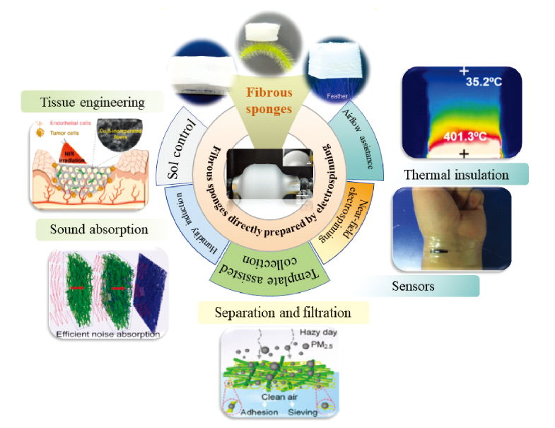
Electrospun fibrous sponge is a fluffy three-dimensional (3D) material based on one-dimensional fibers. The increase of dimension makes this material have many more prominent advantages than traditional electrospun films, so it has shown great application potential in various fields. With the in-depth study of the three-dimensional structure of electrospinning, it has become a current challenge to obtain stable fibrous sponges directly by electrospinning and improve their performance. In this paper, various new strategies for preparing fibrous sponges by direct electrospinning in recent years are reviewed in detail. Firstly, the mechanism, characteristics and representative research results of different methods are analyzed and summarized. Then the application status of this material in the fields of tissue engineering, environmental governance, safety protection and intelligent equipment is introduced. Finally, the future development trend of electrospinning fibrous sponge is prospected.

Contents

1 Introduction

2 Preparation process of direct electrospinning fibrous sponges

2.1 Sol-controlled self-assembly

2.2 Humidity induced phase separation

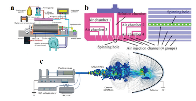
2.3 Air-assisted electrospinning

2.4 Near-field electrospinning/3D printing

2.5 Template-assisted collection

3 Application of direct electrospinning fibrous sponges

3.1 Tissue engineering

3.2 Sound absorption and noise reduction

3.3 Fire protection and heat insulation

3.4 Filtration and separation

3.5 Sensors

4 Conclusion and outlook

Cite this article

Song Yilong , Zhao Shuang , Li Kunfeng , Fei Zhifang , Chen Guobing , Yang Zichun . Preparation and Application of Direct Electrospun Fibrous Sponges[J]. Progress in Chemistry, 2023 , 35(11) : 1686 -1700 . DOI: 10.7536/PC230411

1 Introduction

Electrospinning is the most simple and effective method to produce continuous nanofibers, and its products have broad prospects in the fields of tissue engineering, energy technology, environmental protection, aerospace and intelligent equipment[1~5]. The research and exploration of electrospinning technology, as an important topic in the development of nanomaterials, has attracted wide attention in the scientific community. Nevertheless, the technology has not reached its due height in the integration of industry and learning, which can be attributed to two aspects: (1) the variety of industrial electrospinning products is single, and many functional fibers with excellent properties, such as hollow, core-shell, porous and multiphase structures, have not yet broken through the bottleneck of large-scale preparation[6][7,8][9][10]; (2) The electrospun product is dominated by low-dimensional morphology macroscopically, which is limited by the internal structure of disordered lapping, and its abundant pores and super-tough mechanical potential can not be fully released.
Dimensional expansion is an important means to improve the properties of low-dimensional materials. Referring to the related characteristics of aerogels, which are nanoporous materials that have attracted much attention at present, the concept of "Nano Fibrous Sponges" has been proposed to further develop the size effect of nanostructured and Fibrous materials[11]. Electrospun nanofibers are microscopically similar to aerogel nanopore walls, and are expected to replace the brittle cells of aerogels to obtain 3D porous materials based on flexible nanofibers, thereby improving the brittleness, pulverization and cracking of aerogels, and solving the application problems of traditional porous materials in different scenarios. At the same time, compared with the traditional electrospun film, the three-dimensional nanofiber sponge has more obvious application advantages: (1) it has good self-support and higher mass transfer efficiency, which is an important direction for the development of new sensors; (2) The huge and complex three-dimensional pores make it have large flux, high specific surface area and abundant attachment sites, which broadens the application prospects of the product in filtration, catalysis and other aspects; (3) High-dimensional materials have good expansibility in space, and the structure-activity relationship between porous structure and mechanical properties of materials can be greatly optimized through the orderly design of layered structure, symmetrical structure and topological structure[12].
Currently, the fabrication methods of 3D structures by electrospinning can be divided into two categories, which are secondary molding and direct electrospinning, respectively. Secondary molding is to transform the fiber membrane into 3D porous structure after a series of subsequent treatments (chopping dispersion, freeze-drying, gas foaming, etc.). This method has the advantages of simple principle, good formability and controllable structure, but the preparation time is long and the cost is high, which is not conducive to the large-scale application of sponge[11,14~16]. Directly induced 3D structure formation by electrospinning is a simple and cost-effective method, which basically does not require additional steps or equipment, and mainly controls the electrospinning process to spontaneously form a fluffy structure by using the electrostatic repulsion between the fibers at the collection end or accelerating the solidification of the fibers[17]. The method has the advantages of short process flow and low cost, and is a promising method for constructing the 3D electrospun sponge. In this paper, the latest progress in the research of direct electrospun fiber sponges is reviewed from the aspects of preparation strategies and application status, and the future development direction is also prospected.

2 Preparation of Direct Electrospun Fiber Sponge

In recent years, a variety of electrospinning strategies have been developed to induce 3D fiber formation, including sol control, humidity field regulation, air-assisted electrospinning, near-field electrospinning, and template-assisted collection.

2.1 Sol-controlled self-assembly

The rheological properties of the precursor sol are one of the important parameters affecting the spinning process. It has been shown that factors such as sol concentration and volatility can affect the stacking process of products, and it is a feasible scheme to control the structure of electrospun fibers through sol[18]. It is generally believed that the formation of electrospun 3D structures can be attributed to the rapid solidification of as-spun fibers and the electrostatic repulsion between fibers[19]. In the initial study, it was found that high-concentration solutions induce the formation of macroscopic 3D structure of fibers[20].
Li et al. First reported the stacking process of 3D fibrous sponge structure, and successfully realized the construction of 3D stacking structure by using polyvinylpyrrolidone/nitrate (PVP/N O 3 -) solution and polystyrene (PS) solution as raw materials, respectively.By adjusting the viscosity and charge distribution of the sol, the 2D/3D structure conversion was completed, and it was revealed that the unique fiber packing was mainly due to fiber solidification and electrostatic induction, and that the process also depended on the environmental humidity, solution concentration and volatility[19]. Inspired by this technical route, subsequent studies have prepared polystyrene, sodium alginate, corn protein and other electrospun sponges, and further discussed the charge distribution in the fiber stack (Figure 1)[21][22][23]. After the positively charged polymer jet is subjected to extension, agitation and stretching, and solvent evaporation, the spun fiber is deposited on the receiver, and the surface charge is conducted out through the aluminum foil. Under the influence of the strong electrostatic field, the spun fiber on top of the 3D stack is negatively charged due to electrostatic induction and polarization. As the number of fibers increases rapidly, a film appears on the collector. At the microscopic scale, the film is rough and thick in some areas, and the polymer fibers are polarized under a strong electric field. The negative charge generated by electrostatic induction and polarization on the surface fiber will attract the positively charged jet/fiber, and the stack acts as a new "collection end", and the newly synthesized fiber is deposited on the top of the stack, allowing it to grow rapidly in a short time[21]. Recent studies have found that negatively charged polymers can be spun into fluffy sponge-like structures more than positively charged polymers in high-voltage electric fields, which effectively complements the theoretical basis of the above work[24].
图1 静电纺丝3D结构的(a)俯视图;(b)侧视图;(c)最终结构和(d)顶端纤维电荷分布[21,28]

Fig.1 3D electrospun structure of PS. (a) Top-view, (b) side view, (c) finished size and (d) the fibers on the top of 3D stack repel a rod with negative charges, and attract a rod with positive charges[21,28]. Copyright 2012, Elsevier

In addition to polymer sponges, the process route has also been extended to the preparation of inorganic fiber sponges. Mi et al. Developed a porous silica fiber sponge, and the researchers believed that the chemical chain entanglement of tetraethyl orthosilicate (TEOS)/polyvinyl alcohol (PVA) in the sol was the main reason for the formation of 3D stacking structure.The interaction between the two leads to the formation of siloxane shell between PVA molecules, which makes the composite fiber easily negatively charged due to the electronegativity of silica, and strengthens the loose packing structure of the deposited fiber driven by the electrostatic repulsion between fibers[17][21,25]. Based on the electrospun sponge structure of polyacrylonitrile (PAN), Han et al. Prepared carbon nanofiber sponge by pre-oxidation and carbonization process. Benefiting from the stable mechanical properties and high pressure sensitivity of 3D structure, it has shown great potential in many application fields[26].
The modification and design of single fiber is one of the means of functionalization of electrospun products, and the optimization of single fiber properties based on stable 3D structure is also an important research direction in this field. Mi et al. Developed a superhydrophobic sponge material by crosslinking and fluorinating the silica fiber sponge with glutaraldehyde (GA) and perfluorododecyltriethoxysilane (PDTS) to introduce hydrophobic fluorocarbon chains to the fiber surface, which reduced the surface energy of the fiber, and the modified SiO2-GA-F sponge showed excellent hydrophobic and oil absorption properties[27].
In recent years, with the increasing complexity of electrospinning sol system, the fine preparation of sol-controlled electrospun 3D sponge structure is facing new challenges. Therefore, it is of great significance to further explore the role of each sol parameter in the fiber packing process for the optimization of the process. Vong et al. Studied the effects of additives, crystallinity of fiber and conductivity of sol on 3D structure by experiments, and pointed out that although the addition of additive (HCl) could promote the formation of 3D structure, it would not change the viscosity of sol, and the polarization of a large number of charged particles in sol was the main reason for the formation of 3D structure[28]. This statement is somewhat contradictory to the hypothesis of Li et al. "The increase in the viscosity of the sol caused by the addition of Fe(NO3)3 is the main reason for the accumulation of fibers." Obviously, the former conclusion is more reasonable than the latter[19]. Cheng et al. Designed a 3D reactive electrospinning method controlled by the sol-gel reaction in the jet[29]. Sol with high conductivity (12 910 μS/cm) and low viscosity (18.76 cP) was used as raw material, and the gelation rate of sol jet was controlled by adjusting the protonation degree of colloidal particles.The stability of the jet is significantly reduced by the high-speed stretching of the low viscosity sol, and the jet with high surface potential undergoes a violent whipping instability stage after being stretched into a slender straight jet, forming a 3D coiled structure, and realizing the precise control of the jet shape within milliseconds. Thanks to the interlaced crimp structure between fibers, the material shows excellent structural stability and good recovery ability up to 40% tensile strain, 95% bending strain and 60% compressive strain.
At present, great progress has been made in sol-controlled electrospinning of 3D sponges, and a series of fiber materials with fluffy structure have been prepared. However, there is still a lack of clear theoretical guidance for the design of the sol system, and the spinning process is easily disturbed by environmental factors, resulting in insufficient process stability. Therefore, further clarifying the internal relationship between the sol system and the jet behavior, and optimizing the universality of the sol-controlled electrospinning sponge process should be the focus of future attention.

2.2 Humidity-induced phase separation

In electrospinning, relative humidity is an important parameter that has the ability to affect almost all properties of the fiber, such as morphology, mechanical properties, wetting characteristics, phase composition, chain conformation, and surface potential[30,31]. In recent years, a series of studies have been carried out on the development of nonwovens with 3D fluffy structure by using the high moisture sensitivity of some polymer materials. In high humidity environment, the formation of the fluffy structure of the fiber sponge also depends on the rapid solidification of the jet and the electrostatic repulsion between the fibers, but unlike the aforementioned fiber solidification due to solvent evaporation, the formation of the fluffy structure under this strategy can be attributed to the non-solvent-induced phase separation and the increase of the charge density in the fiber[32,33].
The relative humidity, together with the solvent used, determines the geometry of the fiber[35]. In the "non-solvent-solvent-polymer" ternary system, the non-solvent atmosphere in the environment accelerates the solvent phase separation, that is, before the electrospun nanofibers are deposited on the receiver plate, the curing of the polymer is completed under the induction of the non-solvent vapor, and a large number of nanofibers are stacked to form a 3D fluffy structure[34]. Chen et al. Used PAN and N, N-dimethylformamide (DMF) as spinning raw materials to construct 3D fluffy sponges with low bulk density and high porosity by precisely adjusting the relative humidity, using Flory-Huggins theory.The three-phase diagram of "non-solvent (H2O)- solvent (DMF) -polymer (PAN)" was drawn to analyze the formation mechanism of 3D fluffy structure: the addition of water mist means that the volume fraction of DMF and PAN in the ternary system is decreasing, and the change trend is to move to the phase separation region, that is, to accelerate the curing of PAN[34]. In addition, by changing the relative humidity in the electrospinning conditions, the concentration of free ions in the fibers is changed, which affects the same charge repulsion between fibers and drives the formation of 3D structures[22]. When analyzing the deposition mechanism of PVDF 3D sponge structure under high humidity, Kim et al. Pointed out that high humidity (> 90%) would lead to slow evaporation of solvent in the fiber[33]. The solvent remaining in the fiber also dissociates the polymer electrolyte into charge groups to increase the charge density, and the fiber can be reoriented by similar charge repulsion in adjacent fibers to form a 3D sponge-like structure[22,31].
Research on moisture-controlled 3D bulk-structured nonwovens has focused on the preparation of high moisture-responsive polymer fibers such as polystyrene (PS), polysulfone (PSU), and polyphenylsulfone (PPSU)[26,32,34,37]. In order to enhance the humidity response of other nanofibers in the environmental field of electrospinning and accelerate the hardening process of nanofibers, Yu et al. Added urea to the PAN polymer spinning solution, which increased the moisture absorption of fibers, made the solvent in the jet more easily replaced by moisture in the environment, and promoted the solidification of fibers and achieved a fluffy structure[38]. At present, there are still few studies on the construction of 3D structures based on humidity-regulating hydrophilic polymers. Liang et al. used a hydrophilic polymer (polyethylene oxide) to reveal the relationship between relative humidity and the formation of 3D self-assembled honeycomb polymer structures and their nanofibers, and found that increasing the relative humidity to the critical point (73%) would improve the conductivity and electrostatic repulsion of the rotating jet, and help the nanofibers to complete self-alignment and form 3D honeycomb structures[39].
In recent years, the modification and structure optimization of fiber sponge based on humidity regulation have also been widely studied, which further improves the application prospect of fiber sponge. Ding Bin et al. Of Donghua University used moisture-induced electrospinning technology to manufacture fluffy fiber components with three-dimensional fiber networks, and then formed semi-interpenetrating polymer networks (semi-IPNs) within the fibers through heat treatment to obtain fiber sponges. Fiber sponges based on semi-IPNs have high tensile stress and good fatigue resistance. On this basis, zirconium carbide nanoparticles (ZrC-NPs) were introduced into the fiber, and the ultra-light fiber sponge with superelasticity, effective thermal insulation and photothermal conversion properties was finally obtained[37,40]. In order to further improve the structural stability of electrospun fiber sponges, they prepared a series of fiber sponges with specific microstructures, such as layered structure, gradient structure and interlocking double network, by moisture-assisted multi-step electrospinning and multi-jet blending technology (Fig. 2).Benefiting from the support of the unique and novel elastic unit, these fiber sponges generally have excellent mechanical properties, which provides a new idea for the functional design of electrospun sponges[13,34,36,41,42].
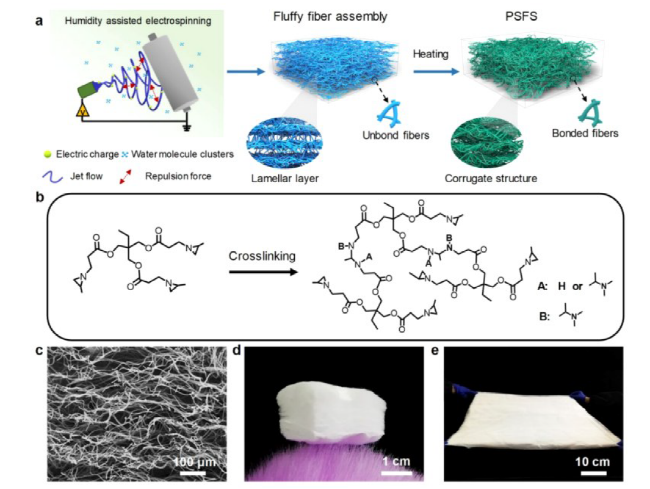
图2 (a) PS纤维海绵制备示意图;(b)交联处理过程中三甲基丙烯三(2甲基-1-丙酸氮吡啶)(TTMA)的化学反应;(c)层状波纹微结构的SEM;(d,e) PS纤维海绵立在羽毛的尖端以及PS纤维海绵的大尺寸照片[36]

Fig.2 (a) Schematic illustration for the fabrication of PSFS. (b) The chemical reaction of TTMA during the crosslink treatment process (c) SEM of the lamellar corrugated microstructure. (d,e) Photographs showing that the ultralight PSFS could stand on the tip of a feather and the large scale of PSFS[36]. Copyright 2019, American Chemical Society

Although humidity-induced phase separation has opened up a simple and stable process path for the preparation of 3D electrospun fiber sponges, it still has some limitations. The theory of non-solvent-induced phase separation determines that this method is only applicable to some humidity-sensitive hydrophobic polymers, and is not universal in the preparation of most hydrophilic polymer fiber sponges and inorganic fiber sponges. In addition, how to realize the precise control of large-scale humidity field in large-scale production is also a practical problem that restricts the further development of the process in engineering.

2.3 Airflow assisted electrospinning

The improvement of equipment to obtain nanofibers with special morphology represents a new direction of electrospinning technology development in recent years, and air-assisted electrospinning is one of the more prominent equipment innovations in this field. This method was first proposed by researchers at Stony Brook University in the United States to solve the problem of fiber refinement in electrospinning with high viscosity solution[43]. Chang et al. Developed a new method to create 3D fiber networks by using heating gas flow control, which provides two oppositely charged polymer jets from a conjugate electrospinning device.An adjustable heat source is used at the middle position of the jet interweaving to provide a controlled upward airflow to balance the gravity, and the turbulence caused by the turbulent mixing of the electrostatic field and the heat source leads to the chaotic motion of the nanofibers, and finally the growth and formation of a large-size 3D nanofiber sphere at the midplane[44]. However, in this process, it is very difficult to maintain the dynamic balance among airflow, gravity and electric field by adjusting the heat source, so it is necessary to construct a relatively stable and controllable airflow field.
Solution blow spinning is a relatively mature spinning and drawing technology at present. Different from electrospinning, this method uses high-speed airflow as the driving force of spinning, and the jet accelerates drying and solidification in the airflow field, which is easier to obtain fluffy fiber structure[45~47]. However, the air flow as a driving force is not enough to stretch the fiber to the nanometer scale, which limits the further improvement of the performance of the sponge material. High-speed airflow was introduced in the electrospinning process, and the vibration of the superimposed airflow field increased the whipping amplitude of the electrostatic jet, thus strengthening the bending instability effect of the jet, which was assembled into 3D nanofiber sponge with ultrafine superelasticity. Zhou et al. Introduced the stepping air flow into the traditional electrospinning system (Fig. 3A, B), and found that the stepped air flow field not only helped to improve the nanofiber yield, but also helped to control the deposition of the formed nanofibers into a fluffy structure in a small area[48]. In order to further exert the bending disturbance effect of high-speed airflow on the jet and overcome the electric orientation effect in the electrospinning process, Guo et al. Reported a synthesis method for preparing zigzag zirconium nanofiber aerogels (ZAGs) by using a turbulent flow field (Fig. 3C): a coaxial blowing device was introduced into the conventional electrospinning system.The high-speed air ejected from the external nozzle first forms a jet, and then transits into the turbulence behind the Taylor cone, forming a complex three-dimensional turbulent flow field. The complex trajectory movement makes the nanofibers entangle with each other, forming a random entwined fiber aerogel structure[49]. Thanks to the carefully designed nanocrystalline structure embedded in the amorphous matrix, the deformation of ceramic fibers under mechanical and thermal excitation has a high-order buckling mode, achieving almost zero Poisson's ratio and thermal expansion coefficient at the macroscopic level.
图3 (a) 分步气流辅助静电纺丝[48]; (b) 纺丝装置侧视图和底部图[48];(c) 湍流辅助静电纺丝[49]

Fig.3 (a) Schematic diagram of stepped airflow-assisted electrospinning set-up[48]. (b) Side and bottom views of the spinning unit[48]. (c) Illustration of the turbulent-flow-assisted electrospinning[49]. Copyright 2022, Nature

At present, most fiber sponges can be prepared by air-assisted electrospinning technology in theory. However, because this method is in its infancy, the number of related products is small, and there is a lack of systematic research experience and results. Therefore, optimizing the process and equipment of air-assisted electrospinning, and further exploring the effects of gas flow rate, gas flow distribution, turbulence control and other factors on the formability of fluffy sponges will open up new space for the flexible preparation of 3D sponge structures.

2.4 Near-field electrospinning/3D printing

The chaotic nature of conventional electrospinning limits its application in patterned micro/nanoscale fiber structure devices. In order to improve the controlled deposition of electrospun fibers, near-field electrospinning (NFES) has been proposed and developed in recent years[50,51]. In the NFES process, the bending instability is significantly limited due to the reduction of the spinning distance, so that the fiber can be controllably deposited in the straight stage. NFES implements position-controlled deposition in pre-designed trajectories and builds aligned fibers and 3D fiber structures.
With the development of 3D printing technology, the combination of electrostatic direct spinning and 3D printing has made important progress in the preparation of controllable 3D stacked nanofiber structures. Luo et al. Proposed a "self-aligned" three-dimensional near-field electrospinning method, which successfully realized the consistent repeated stacking of spun fibers and prepared a variety of 3D microstructures with controllable structures and high aspect ratios (Fig. 4)[52]. In order to further improve the accuracy of electrostatic direct spinning nanostack structures, Park et al. Constructed self-aligned, template-free 3D stacked nanostructures by simply adding inorganic salt (NaCl) to the polymer solution.Benefiting from the increase in the conductivity of the polymer solution, the effective charge dissipation of the deposited fibers is accelerated, which in turn leads to a higher attraction between the nanofiber jet and the deposited fibers, improving the focusing degree of the self-aligned jet[53]. However, the construction of 3D structures based on this method is limited to the micron level, which limits its application in large-size commercial devices.
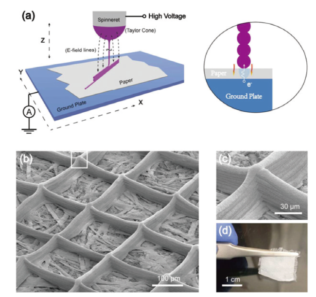
图4 (a)3D静电纺丝过程的示意图和堆叠纤维的特写示意图;(b)在纸基材上构建的10层3D网格结构的SEM图像;(c)网格交叉区域的SEM图像;(d)整个样品的光学照片[52]

Fig.4 (a) Schematic setup of the 3D electrospinning process and a close-up schematic of stacked fibers. (b) SEM image of a 10-layer 3D grid structure on paper substrate. (c) SEM image showing the cross-over area of the grid. (d) An optical photo showing a whole grid structure[52]. Copyright 2015, American Chemical Society

Vong et al. Realized the rapid preparation of macroscopic 3D structures by controlling different sol parameters in near-electric direct spinning[28]. This device, called "3D electrospinning", can control the movement of the nozzle to control the position of the fiber deposition area during electrospinning, and use additives to enhance the polarization and electrostatic induction during fiber deposition to obtain a relatively fluffy fiber structure. In another study, they reported in detail the preparation of different PS sponges such as hollow cylindrical, triangular, pentagonal and polygonal sponges by using the device.The effects of solution concentration, applied voltage, working distance, flow rate and nozzle moving speed on the spinning process were discussed. Thanks to the optimized experimental conditions, the sponge with a height of about 3 ~ 4 cm can be prepared rapidly within 10 min[54]. However, the spinning height in this experiment is much larger than the working distance of the needle in NFES, which aggravates the instability of the jet and sacrifices the accuracy of product stacking.
Near-field electrospinning combined with 3D printing technology can produce 3D products with customized structures, which provides a new way for the controllable preparation of electrospun 3D structures. However, the high accuracy of this method is based on the miniaturization of products, and the construction of most large-scale structures inevitably goes through the process of jet instability whipping. Therefore, the precise control of large-size structures cannot be achieved at present, which will seriously restrict the application prospects of the products of this technology in most fields.

2.5 Template-assisted collection

The collection end morphology is the most direct factor affecting the packing arrangement of electrospun nanofibers, and the method of directly preparing 3D nanofiber structures by using special collection devices has attracted wide attention. At present, there are mainly three kinds of 3D-assisted collection based on different principles: (1) using different substrate support systems to control the deposition state of fibers, such as liquid collector, frozen collector, etc.[55,56]; (2) controlling the jet behavior by affecting the electrostatic field distribution through the geometric design of the collector, such as divergent electrospinning constructed by a double inclined collector[58~62]; (3) Various 3D collection templates are used to induce the attachment and growth of fibers and promote the orderly deposition of fibers, such as hemispherical, reticular and other complex shape collection devices[63~65].
The resistance, flowability, and support of the liquid have a unique influence on the fiber deposition behavior, so the use of a liquid collection device enables the controlled alignment and three-dimensional stacking of electrospun fiber structures. Yousefzadeh et al. Reported a technique to construct various nanofiber 3D structures using a water-supported system, which benefited from the optimized electrostatic field and the discharge effect of the deposited fibers, and realized the rapid stacking of fluffy structures such as nanofiber rings and spindle-shaped nanofiber rings[55]. Studies have shown that the pore structure of the fiber is closely related to the surface tension of the receiving bath. In recent years, the controllable preparation of various fluffy 3D structures such as polyacrylonitrile, polycaprolactone, silk fibroin and composite fibers has been realized by selecting low surface tension liquids instead of pure water as the receiving medium[66][67~69]. In addition, besides liquid receiving, ultra-low temperature freezing receiving also provides a possibility for the rapid deposition and solidification of fiber sponge. Schneider et al. Used a drum filled with dry ice as the collecting end, and the ultra-low surface temperature caused the fiber to rapidly produce ice crystals and solidify, obtaining a flexible and plastic cotton-like poly (lactic acid-co-ethylene glycol) and amorphous tricalcium phosphate nanoparticle composite[56]. Compared with liquid-assisted collection, the method does not need to remove excess solvent, and the obtained product has better environmental protection and biocompatibility.
The electric field force is the main driving force of the electrospinning jet, which has the most significant influence on the jet path and fiber distribution. In the experiment, special collection devices are generally configured to create different electric field environments, so as to realize the three-dimensional design of spinning fibers. Mi et al. Achieved rapid self-assembly of 3D silica fibers by placing a conductive tip in the collection device[70]. The process does not rely on sol control, but uses the electric field of the tip to guide the directional deposition of fibers. The deposited fibers are negatively charged due to electrostatic induction, and these fibers act as new tips to attract the subsequently deposited fibers. Since the fibers initially have the same charge, they tend to repel each other when deposited at the same tip, resulting in a loosely combined structure. In order to further improve the structural controllability of 3D sponge, researchers have proposed a divergent electric field spinning technology based on double inclined collectors[58~60]. Zaman et al. Successfully prepared 3D nanosponges with gradient density by using this technology, and predicted the density gradient of nanofibers inside the collector during divergent electrospinning by statistical methods.The relationship between collector design factors and 3D nanofiber density distribution was explored, providing a practical strategy for the controllable design of 3D nanofiber matrix microstructure gradient (Fig. 5)[62].
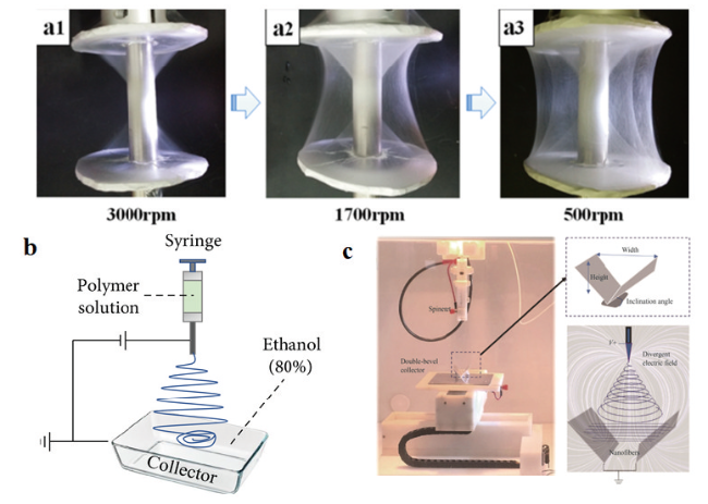
图5 (a)“哑铃”收集器上的3D纳米纤维宏观结构[61]; (b)液体收集器制备3D纳米纤维结构示意图[67]; (c) 发散静电纺丝装置[62]

Fig.5 (a) Three dimension nanofibrous macrostructures on “dumbbell” collector[61]. (b) The schematic set-up for the production of 3D nanofibrous structures (bulk and aligned) using liquid vortex[67]. (c) Configuration of divergence electrospinning[62]. Copyright 2021, Springer Berlin Heidelberg

It is shown that different alignment and orientation ratios of electrospun nanofibers can be obtained by changing the design of the collector in the electrospinning process[71]. Therefore, various 3D collectors with complex shapes are widely used in the preparation of electrospun fiber sponges, which is expected to meet the specific needs of some practical scenarios for the shape of fiber sponges. Shah Hosseini et al. Used 3D printing technology to obtain an electrospinning collection template with fine 3D patterns, and based on this, 3D fiber structures with different orientations were prepared[65]. Kim et al. Designed a new collection device combined with the auxiliary electric field technology, and successfully fabricated a 3D hemispherical transparent scaffold with radially arranged nanofibers by using a pin-top collector composed of a conductive metal needle and a hemispherical non-conductive template[63]. In order to solve the problem that the conformal template collector is difficult to separate from the electrospun nanofibers and further improve the structural complexity of 3D nanofibers, Song et al. Prepared a flexible printable graphene nanoplate-carbon nanotube-polydimethylsiloxane (GCP) composite conductive coating as the collector.The collection of the nanofiber structure on the complex 3D non-conductive conformal substrate is realized, and the nanofiber sponge can be directly used as a tissue engineering scaffold without being separated from the collection substrate due to the good biocompatibility of the GCP coating,It opens up a new idea of direct combination of nanofiber sponge collection and application, and effectively makes up for the shortcomings of fiber materials in functional application[72].
Through the targeted design of the collection process of electrospinning, the structure specificity of electrospun nanofiber sponge was improved, and a batch of fiber materials with integrated structure and function were prepared. However, the existing collection methods are still unable to meet a large number of specific needs in various fields. Therefore, continuing to innovate the fiber collection methods is the direction to promote the further development of electrospun sponges in the future.

3 Application of Direct Electrospun Fiber Sponge

The expansion of the spatial dimension structure endows the electrospun sponge with many unique advantages, which makes it show excellent application potential in the fields of tissue engineering, sound absorption and noise reduction, fire resistance and heat preservation, separation and filtration, and sensing.

3.1 Tissue engineering

With large specific surface area, excellent physicochemical properties and controllable pore size, electrospun nanofibers can mimic extracellular matrix (ECM) and some human tissues, provide structural support for cells, and regulate cell attachment, diffusion, migration and differentiation[73]. Compared with traditional 2D fibers, 3D scaffolds can better connect single cells and organs, providing new directions for cell-cell interactions, cell migration, and cell morphological changes, which play an important role in regulating cell cycle and tissue function[74]. Therefore, the application of various in vitro ECM-mimicking electrospun tissue scaffolds in biomaterials has increased rapidly in recent years[75~78]. Walser et al. Used a conductive ear-shaped mold as a collector to prepare an auricle-shaped PCL fiber scaffold, in which bovine ankle chondrocytes were implanted.Artificial auricle cartilage tissue was obtained by in vitro culture. Benefiting from the rapid proliferation of cells and the good structure of the electrospun 3D scaffold, the tissue showed excellent local mechanical properties close to the original cartilage[79]. It is generally believed that mimicking the natural ECM structure requires electrospun scaffolds with both ultrafine fiber diameter and large pore size to ensure cell infiltration and diffusion of nutrients in the scaffold[80].
McClure et al. Designed a porous collector. Air flows from the pores at a specified rate, and the airflow impedance interferes with the close packing of the electrospun fibers, thus changing the pore size, permeability, and other properties of the electrospun PCL scaffold[81]. The data show that a stable electrospun scaffold with a pore size of 7 μm can be obtained at a pressure of 100 kPa, while the scaffold formed at 50 kPa has the maximum permeability. The design of the porous axis improves the porosity of the fiber scaffold and effectively increases the amount of cell permeability without compromising the mechanical properties and structural integrity.
In addition to maintaining tissue structural integrity, 3D sponges can also enhance the mechanical properties and drug penetration ability in tissue engineering applications through different fiber orientations and composite hydrogels. Bosworth et al. compared the application effects of electrospun random fiber membrane, oriented fiber membrane and 3D fiber bundle scaffold in tendon tissue repair, and the results showed that the oriented fiber membrane and 3D fiber bundle could simulate the parallel distribution of collagen fibers in natural tendon, and give full play to the potential of biomimetic engineering tissue[82]. Eom et al. Developed a novel hydrogel-assisted electrospinning process. Benefiting from the sol-gel transition characteristics of hydrogels, the 3D hydrogel collector can be used as a collector sacrificial template and a drug/cell encapsulation structure, resulting in complex macrostructures and drug/cell-embedded hydrogels, respectively (Figure 6)[83]. However, the development of electrospun scaffolds with highly biocompatible fibers and biomimetic gradient structures for complex tissue regeneration is still in the blank, and the interdisciplinary research of material engineering and tissue engineering should continue to be promoted in the future to lay the foundation for various applications of electrospun materials in the biological field.
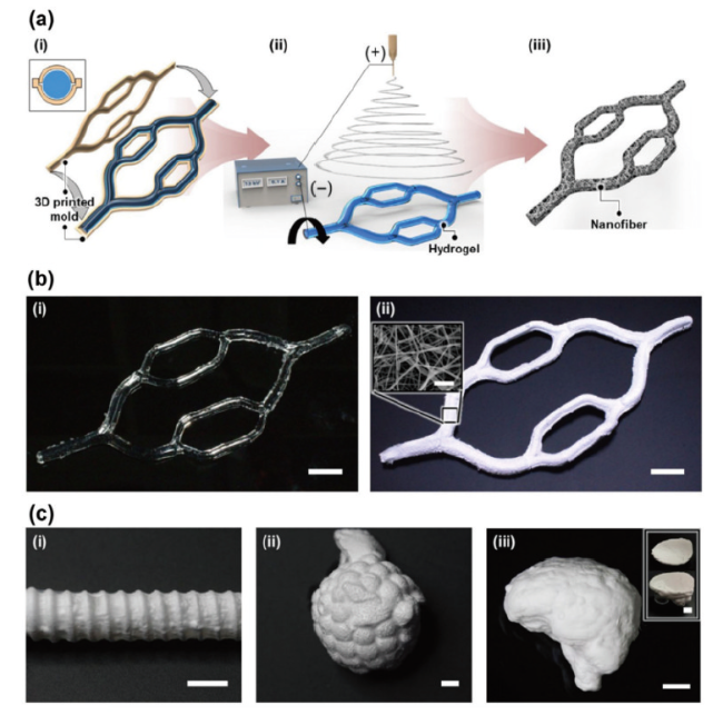
图6 (a)水凝胶辅助静电纺丝(GelES)在成型和静电纺丝两个过程的示意图;(b)多分叉三维明胶圆柱形结构和三维PCL纳米纤维宏观结构照片;(c) GelES制造的各种复杂的三维宏观结构的照片,包括波纹管状宏观结构(c-i)、微型化人类肺泡状宏观结构(c-ii)、类脑壳宏观结构(c-iii)[83]

Fig.6 (a) Schematic diagram of hydrogel-assisted electrospinning (GelES) with the two sequential processes of molding and electrospinning; (b) photographs of the multi-bifurcated 3D gelatin cylindrical structure and the 3D PCL nanofiber macrostructure; and (c) photographs of various complex 3D macroscopic configurations fabricated by GelES including the bellow-shaped tubular macrostructure, miniaturized human alveoli-like macrostructure, and brain-like shell macrostructure. Copyright 2020, American Chemical Society

3.2 Sound absorption and noise reduction

The unique microporous structure makes the electrospun nanofibers have the characteristics of large specific surface area and high porosity, which is conducive to the diffusion and consumption of sound waves in the material. However, the 2D fiber membrane is thin and dense, resulting in a single internal structure and a narrow sound absorption band, so it usually forms a 3D structure to promote the consumption of sound energy, and increases the thickness to extend the sound wave dissipation path and improve the sound absorption performance of the material[44].
The thickness variation of electrospun fibers can be achieved by adjusting the electrospinning time. Zou et al. Reported the change of sound absorption properties of polyurethane (PU) and polyvinylidene fluoride (PVDF) nanofiber mats at different spinning time, and found that the sound absorption properties of PU and PVDF nanofiber mats were significantly enhanced when the electrospinning time was increased from 2 H to 4 H[84]. Ozkal et al. combined several PU nanofibers (electrospinning time 5, 20, 60 and 120 min) with other materials to produce composite sound-absorbing materials.It was found that the resonance frequency of the composite decreased with the increase of electrospinning time, and the thicker nanofiber web could provide higher sound absorption efficiency in the lower frequency range, and there was a statistically significant difference in the noise reduction coefficient of the composite at different time[85].
Traditional electrospun sponges obtain a fluffy structure by simple stacking, which is not stable enough in application. To solve this problem, Cao et al. Prepared an electrospun ultrafine fiber sponge derived from microstructure, which achieved excellent resilience and high sound absorption properties thanks to the layered corrugated structure used as the elastic unit (Fig. 7)[36]. Even if it is deformed under the load of 8900 times the weight, it can quickly recover to the original height. It can still maintain its structural stability after 100 cycles at 60% strain. More importantly, the initial hierarchical structure and hydrophobicity of the prepared materials endow them with ultra-light density, excellent low-frequency sound absorption and structural stability. In addition, in order to improve the structural and functional complexity of fiber sponges, Bai et al. Used polyetherimide (PEI) and elastic polyester (PU) functional fibers as matrices to construct a three-dimensional fiber network integrating flame retardancy and sound absorption through humidity-assisted electrospinning and in situ crosslinking.The PEI/PU fiber sponge has ultra-light, super-elastic, flame retardant and good sound absorption properties, which provides a new idea for the design of multi-scene sound absorption materials in the future[86].
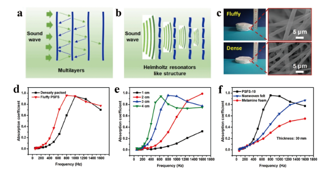
图7 (a) 声能经梯度结构纤维海绵(PSFS)多层反射而耗散;(b) 类亥姆霍兹谐振器结构消耗能量;(c) 致密纤维和蓬松PSFS-10的宏观和微观结构比较;(d)等重量的PSFS和密堆积纤维的吸声性能比较;(e)不同厚度的PSFS的吸声性能;(f)商业吸声材料和PSFS的吸声性能的比较[36]

Fig.7 (a) Energy of sound is consumed by reflections multilayer in gradient structure fibrous sponge (PSFS). (b) Energy consumed by Helmholtz resonators like structure. (c) Comparison of the macro and microstructure for dense-packed fibers and fluffy PSFS-10. (d) Sound absorption performance of PSFS and dense packed fibers in a similar weight. (e) Sound absorption performance of PSFS with various thicknesses. (f) Comparison of the sound absorption performance for the commercial sound absorption materials and the prepared PSFS[36]. Copyright 2019, American Chemical Society

In order to achieve a better broadband sound absorption effect, Feng et al. Prepared a gradient structure fiber sponge with superelasticity and stretchability by moisture-assisted multi-step electrospinning and a unique physical/chemical dual crosslinking method. The sponge has a maximum tensile strength of 169 kPa and can support 10,000 times its own weight without breaking[41]. In addition, the material maintains a stable structure after 500 compression cycles at 60% strain, while having lightweight properties and hydrophobicity. Benefiting from the gradient change of porosity and pore size in the Z direction, the ability of fiber sponge materials to absorb broadband sound waves is significantly enhanced (the noise reduction coefficient is up to 0.53), which opens up a new way for the development of sound absorption materials.
Ultrafine fibrous porous materials prepared by electrospinning technology show broad application prospects in the field of noise reduction, especially the development of multi-component gradient fiber sponge, which makes up for the size dependence of traditional materials on volume and thickness in the field of low-frequency sound absorption. However, the preparation process of multi-component sound-absorbing sponge based on solution electrospinning and humidity regulation can not overcome its inherent defects, and the problems of low efficiency and solvent pollution still need to be solved.

3.3 Refractory insulation

The structural characteristics of electrospun fiber sponge, such as small pore size, high porosity and large specific surface area, can effectively extend the phonon motion path and limit the thermal convection of gas molecules. However, the current fiber sponges are usually assembled by short nanofibers in a point-to-point manner, which leads to the limited effective stress area and makes it difficult to resist large external stress. Therefore, the development of direct electrospun fiber sponges with high continuity and good compression resilience has become an important trend in the development of lightweight and efficient thermal insulation materials.
Natural materials mostly have both hard and soft components, which give them strong and soft mechanical properties. Inspired by this, Zhao et al. Introduced elastomer PU into PSU fiber by electrospinning. PSU can form a stable fluffy structure in high humidity environment, while PU can absorb the deformation energy caused by external force, which improves the fragile characteristics of PSU fiber. Phosphazene flame retardant was added to the spinning solution.The composite fiber sponge ensures that the material has stable mechanical properties and efficient flame retardancy, the elongation at break reaches 160%, the composite fiber sponge has unique compression elasticity, almost no plastic deformation after 100 times of compression tests, and the composite fiber sponge has ultra-low density and thermal insulation properties superior to those of the traditional polyester felt[35]. In order to further improve the structural stability and functional complexity of fiber sponges, Zhang et al. Selected three different polymers to construct three-dimensional fluffy PPSU/PU/PAI fiber sponges by precisely adjusting the relative humidity[32]. Among them, the PPSU component has a rapid phase separation behavior at high relative humidity and is easy to form a relatively fluffy structure; The high elasticity of PU provides the fiber sponge with good resistance to external deformation; The introduction of high-strength polyamide-imide (PAI) nanofibers with high limiting oxygen index improved the high temperature resistance of the material. The mechanical properties and flame retardancy of the fiber sponge are greatly optimized by using the difference of the properties of different materials.
Using high infrared reflectivity particles to modify fabrics to reduce radiation heat dissipation is an important direction for the development of advanced thermal insulation materials. Zirconium carbide (ZrC), which can absorb sunlight and convert it into heat, has shown broad potential in this field. Wu et al. Assembled fibers containing ZrC nanoparticles into 3D structures and created semi-interpenetrating polymer networks to obtain ultra-light and super-elastic fiber sponges for new thermal insulation materials[40]. The fiber sponge has high heat preservation capacity and effective photothermal conversion performance, and can increase the temperature of the fabric to 70.3 deg C under sunlight. In addition, the material has low density, low temperature superelasticity and good hydrophobicity, which provides a new method for developing high-performance thermal insulation materials for personal cold protection.
Table 1 is a comparison of the thermal insulation performance of different fiber sponges. It can be seen that the service temperature range and thermal insulation performance of different materials are quite different. With the development of cutting-edge technology in aerospace, military, civil industry and other fields, the demand for high strength and high temperature resistant ceramic aerogel materials for extreme environment insulation is more urgent. However, in practical applications, the poor mechanical properties and thermal shock instability of ceramic aerogels limit their further application. Therefore, all-ceramic fiber sponges with low density and high temperature resistance are considered as promising thermal insulation materials[49]. Zhang et al. Combined flexible ZrO2-Al2O3 nanofibers with a Al(H2PO4)3(AHP) matrix to prepare a ZrO2-Al2O3 nanofiber aerogel (ZrAlNFAs) with an anisotropic layered structure (Fig. 8). The aerogel has a layered structure composed of multiple sets of arches stacked in parallel, and exhibits high compressive strength and good fatigue resistance at 90% strain[87]. In addition, the layered structure, high porosity (> 98%), and all-ceramic composition endow ZrAlNFAs with temperature-invariant compressibility, high refractoriness up to 1300 ° C, thermal conductivity as low as 32mW·m-1·K-1. Subsequently, Dong et al. Reported a more convenient method, sol-controlled electrospinning, to prepare ultra-low density ZrO2-TiO2 fiber sponges[88]. Due to the different solidification speed everywhere on the fiber, the fiber gradually bends and forms a supporting structure, and the fiber membrane becomes a 3D fiber sponge. The layered sponge has a low density of 9.5 mg·cm-3 after heat treatment at 1200 ° C, high compressibility and good compression resistance over a wide temperature range of − 196 to 1200 ° C. In addition, sponge also has a low thermal conductivity of 27 mW·m-1·K-1, strong fire resistance and high near-infrared reflectivity, making it an ideal substitute for high-temperature thermal insulation materials.
表1 耐火隔热纤维海绵的性能对比

Table 1 Performance comparison of electrospun fiber sponges applied in the field of fire resistance and thermal insulation

Material Preparation method Working temperature (℃) Thermal conductivity(mW·m-1·K-1) Mechanical property Applications ref
PSU/PU Humidity induced phase separation / 27.08 Elongation at break is 160% Insulation and flame retardant in cold environment 35
Mullite Sol-controlled self-assembly -196~1300 22.8 The tensile strain is 100% Thermal protection system of aircraft 29
ZrO2-TiO2 Sol-controlled self-assembly -196~1200 27 / Insulation at high temperatures 87
PMMA/PU Humidity induced phase separation / 25.28 The tensile stress is 159.02 kPa Thermal insulation material 13
PSU/PU Humidity induced phase separation -196~ 25.8 The tensile stress is 1 MPa Heat preservation in cold environment 37
PPSU/PU/PAI Humidity induced phase separation / 24.6 ~0% plastic deformation after 100 compressions tests at a large compressive strain of 50% Heat preservation in cold environment 32
PSU/ZrC Humidity induced phase separation -100~100 25.2 The material could withstand over 10 000 times its weight Thermal insulation and photothermal conversion in cold environment 40
ZrO2 Air-assisted electrospinning ~1300 26(25℃) Poisson’s ratio and thermal expansion coefficient are almost 0 Thermal insulation at extreme high temperatures 49
104(1000℃)
ZrO2-Al2O3 Stack layer by layer ~1300 32.2 High compression strength of more than 1100 kPa (at a strain of 90%) Thermal insulation at extreme high temperatures 86
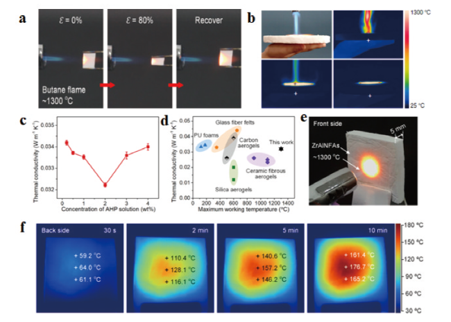
图8 ZrO2-Al2O3纳米纤维气凝胶(ZrAlNFAs)的隔热性能。(a) ZrAlNFAs的热导率; (b)室温下的热导率与气凝胶类材料的最高工作温度的关系; (c)正面经受丁烷喷灯火焰的光学照片;(d) 10 min加热过程中背面的红外图像; (e)背面中心点随时间变化的温度曲线; (f)经过10 min的耐火测试后ZrAlNFA正面和横截面的光学照片和电镜照片[87]

Fig.8 Thermal insulation properties of the ZrAlNFAs. (a) Thermal conductivities of the ZrAlNFAs. (b) Thermal conductivity at room temperature versus maximum working temperature for aerogel-like materials. (c) Optical photograph of the front side subjected to a butane blowtorch flame. (d) Infrared images of the back side during the 10 min heating process. (e) Time-dependent temperature profile of the center point on the back side. (f) Optical photograph and SEM image of front side and cross section of the ZrAlNFAs after a 10 min fire resistance test[87]. Copyright 2020, American Chemical Society

To sum up, the research of electrospun sponge in the field of refractory and thermal insulation has made a series of gratifying progress. However, with the continuous development of national defense industry and aviation industry, higher requirements are put forward for the performance of materials. Therefore, it has become an important research direction in this field in the future to prepare super thermal insulation materials with thermal shock resistance, high strength, compressibility, stretchability and bendability by giving full play to the composite advantages of electrospun sponge and aerogel.

3.4 Filtration separation

The preparation of high efficiency nanofiber filter materials by electrospinning is an important means to solve the problem of environmental pollution. However, the closely packed 2D structure generally has a large filtration resistance, which makes it difficult to achieve a balance between removal efficiency and permeability[34]. Therefore, 3D sponge, which has low filtration resistance and high dust holding capacity, has gradually received special attention as a key material to replace traditional filters[42,89,90].
Electrostatic effect, interception effect and screening effect are all important mechanisms for the function of fiber-based air filter materials. The air filter with multi-stage network structure can give full play to the synergistic effect of the above mechanisms and improve the comprehensive filtering effect of the material (Figure 9)[91~93]. Chen et al. Proposed a new non-woven fabric filter with honeycomb structure composed of PSU and PU nanofibers, which can give full play to the superposition effect of multiple filtration mechanisms through the uneven distribution of fiber diameter and fiber density.The coarse fiber region provides superior mechanical properties, while the charged fine fiber region guarantees ideal air filtration efficiency and high filtration resistance, resulting in higher filtration effect and better mechanical strength of the material[90]. Because the production of this nanofiber filter does not require complex processes, it can be prepared on a large scale on needle-free electrospinning equipment, showing great potential in both industrial and civil filtration. In order to further enhance the structural stability of fiber filter materials and expand the application scenarios of materials in the field of liquid adsorption, they also reported a 3D ultrafine fiber module based on dual-pore characteristics, which simply combines binary solvent system with humidification device.Layered pores are simultaneously generated on various negatively charged polymer fibers, and the porous structure is bonded by steam to improve the structural integrity of macropores, which finally endows the 3D fiber module with low density, high elasticity and excellent cycle compressibility, so that it shows excellent performance in oil-water separation, oil absorption and air filtration[94].
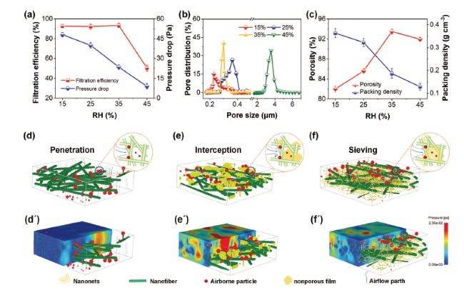
图9 双网络结构纤维海绵。(a)使用PM0.3颗粒物且气流速度为5.33 cm·s-1时的过滤效率和压降; (b) 孔径分布; (c)在不同RH下制备的双网络结构PAN纳米纤维网络的孔隙率和填充密度; (d~f) PAN纳米纤维过滤器在有无空隙下捕获空气中颗粒的过程示意图;(d'~f')气流在5.33 cm·s-1的面速度下通过这三个过滤器时的压力场模型[42]

Fig.9 Dual-Network structured fibrous sponges. (a) The filtration efficiency and pressure drop when PM 0.3 particles are used and the airflow velocity is 5.33 cm·s-1. (b) Pore size distribution. (c) The porosity and filling density of PAN nanofiber networks with dual network structure prepared at different RH. (d~f) The process diagram of PAN nanofiber filter capturing particles in the air with or without voids. (d' ~f') The pressure field model of airflow passing through these three filters at a surface velocity of 5.33 cm · s-1 [42]. Copyright 2019, Wiley-VCH Verlag

In the field of liquid separation, the bulk structure and surface properties of fiber sponge are important factors affecting its adsorption capacity. Various carbonaceous sponges have been developed as oil adsorption materials because of their highly porous structure and inherent hydrophobicity and lipophilicity, but the high cost and complex preparation process seriously restrict the large-scale application of carbonaceous adsorption materials[95~98]. Tai et al. Prepared a sponge material composed of interconnected 3D structures of carbon-silica nanofibers through an economical and easy-to-operate electrospinning technique, which is a promising adsorbent material with high porosity, ultra-low density, hydrophobicity, lipophilicity and high compressibility[99]. Tests show that the sponge has high adsorption capacity and fast absorption rate for various petroleum derivatives and organic solvents, and can adsorb up to 140 times of its own weight of petroleum. Through cyclic distillation or mechanical pressing, petroleum recovery and reuse of the sponge can be realized. Selective removal and recovery of oil in harsh environment is one of the important topics in the field of environmental protection. Mi et al. Developed a stable fluorinated silica fiber sponge, which can be used as an efficient absorbent for selective oil absorption in harsh environment[100]. Silica fiber sponges were prepared by self-assembly electrospinning and calcination, and superhydrophobic silica sponges were obtained by crosslinking and fluorination with glutaraldehyde (GA) and perfluorodecyltriethoxysilane (PDTS).The sponge's fluffy micro-scale fiber structure and low surface energy help to improve its adsorption capacity for various oils, with an adsorption weight 122 times its own weight, excellent separation efficiency, and good stability in harsh environments and repeated use. In addition, GA crosslinking endows silica sponge with high dimensional stability and recyclability, and these properties greatly improve the application value of this material in different scenarios.
According to the above reports, electrospun sponges have shown great potential in air filtration and oil-water separation. But in other areas of environmental protection, there are still many serious problems that cannot be solved. For example, the current filter materials lack efficient means to remove toxic components and radioactive substances in air and water, so it is particularly necessary to improve the comprehensive treatment capacity of filter materials.

3.5 Sensor

With the development of intelligent electronic devices, flexible sensors suitable for non-flat surfaces are increasingly used in multiple scenes. In recent years, researchers have combined nanoparticles with electrospun fibers to construct a series of nanofiber sensors with orderly structure and excellent performance[101~102]. However, the sensing devices based on traditional 2D electrospun films have low sensitivity, small linear working range, and poor durability. Therefore, researchers have developed various new structures to continuously optimize the sensitivity and linear detection range of the sensors[103][14,49,104,107].
Fiber freeze-forming is currently the main method to create hierarchical porous hyperelastic sponges, which enables electrospun nanofibers to be assembled into elastic block structures with adjustable density and shape on a large scale, and to create abundant attachment sites and high elastic response speed[108~110]. Subsequent researchers directly prepared 3D sponges for pressure sensors by using mature electrospinning technology, which broke the dimensional limitation of traditional electrospun materials and overcame the fragility of carbon-based materials, and prepared multifunctional 3D carbon nanofiber networks with excellent pressure sensitivity by electrospinning and heat treatment. The material has a high degree of pressure-sensitive performance far higher than that of similar 3D porous materials, and thanks to the reinforcement of in-situ doped Al2O3, the carbon nanofibers show excellent flexibility, stable elasticity and excellent fatigue resistance, and the pressure sensor designed with the material has a strong ability to monitor voice, pulse, respiration and human joint movement (Fig. 10)[26].
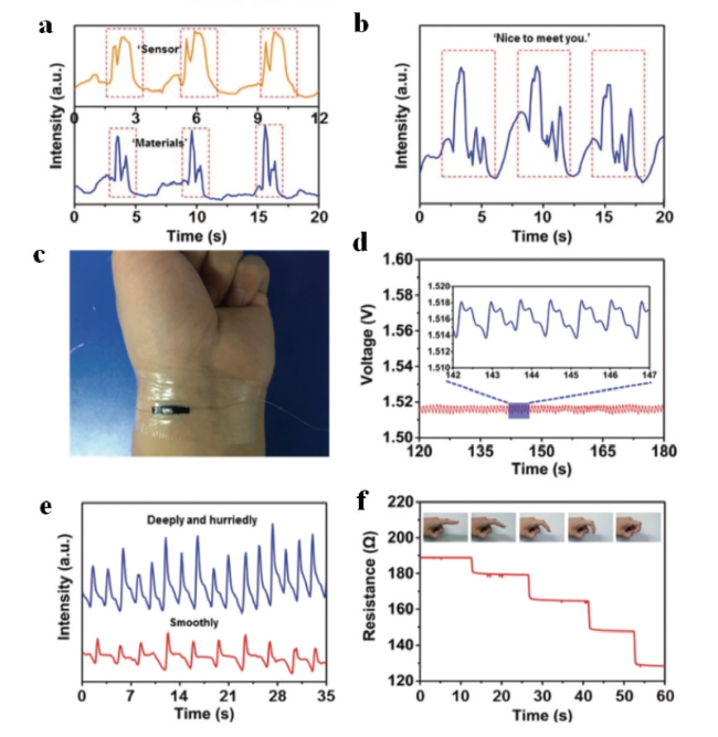
图10 由CNFNs组装而成的可穿戴设备。(a、b)发音期间的实时阻抗响应;(c)固定在手腕上测量脉搏的CNFN传感器的照片;(d)具有清晰波形的脉冲信号,指示每分钟76次搏动;(e)分别由平稳呼吸和急促呼吸的空气运动引起的呼吸信号;(f)附着在手指关节上的CNFN传感器对不同弯曲程度的电阻响应[26]

Fig.10 Wearable device assembled from CNFNs for various physiological signal monitoring. (a and b) Real-time resistance response during pronouncing. (c) Photograph of the CNFN sensor fixed on the wrist to measure the pulse. (d) Pulse signal with clear waveforms, indicating 76 beats per min. (e) Respiratory signal caused by air movements for breathing smoothly and hurriedly, respectively. (f) Resistance responses of the CNFN sensor attached to the finger joint for different degrees of bending[26]. Copyright 2019, Royal Society of Chemistry

At present, the high responsivity and sensitivity of electrospun carbon-based fiber sponges as new sensors have contributed to the vigorous development of wearable smart electronic devices. However, there is still a certain gap between carbon-based materials and traditional conductive metals in terms of strength and chemical stability. In addition to structural optimization, composition modification should be carried out to further improve the comprehensive properties of carbon-based conductive materials.

4 Conclusion and prospect

As a new type of porous material, fiber sponge has shown broad application prospects in tissue engineering, sound insulation and noise reduction, fire resistance and insulation, filtration and separation, environmental protection and intelligent equipment due to its unique three-dimensional pore structure, high specific surface area, large aspect ratio and excellent mechanical properties. At present, the preparation process of direct electrospun fiber sponge still faces many challenges. For example, the electrospinning process based on sol control is easily affected by complex environmental factors, resulting in insufficient process stability and poor repeatability. It is difficult and key to clarify the relationship between sol system, environmental factors and jet behavior. The preparation of 3D sponges by humidity-induced phase separation has some limitations in the scope of application, which is only suitable for humidity-sensitive hydrophobic polymer solvents, and the precise control of a wide range of humidity fields in large-scale preparation is also a major challenge for this technology. The air-assisted spinning method faces great difficulties in the steps of high-speed airflow orientation control and fiber collection, and the shape controllability of the obtained sample is poor. Near-field electrospinning can not produce large-size fluffy fiber sponges, which seriously limits the application range of its products. The 3D collection template needs to design and modify the experimental device, which increases the preparation cost of electrospun sponge, and the separation of template and fiber is also one of the technical problems faced by this method.
Based on the above research status of direct electrospinning fiber sponge, it can be expected that the future research of this material will seek breakthroughs in the following aspects: (1) in-depth study of the formation mechanism of 3D structure under different technical routes. In that exist preparation method, sponge forming depend on the solidification of fiber before collection no matter adding volatile solvent, induce phase separation or airflow blowing,The formation of fiber sponge is affected by many complex factors, so it is of great significance to determine the boundary conditions of different process parameters in fiber curing for guiding the design and preparation of direct electrospun fiber sponge. (2) Further simplify the preparation process and develop a process route that is easy to produce 3D structures in large quantities. Compared with freeze-drying and other electrospinning sponge preparation technologies, direct electrospinning has the advantages of short time consumption and low energy consumption, but because of its single product structure and poor controllability, it usually needs to add follow-up treatment links (layer-by-layer stacking, heat treatment, etc.).It is necessary to develop a simple and low-cost large-scale production technology to directly prepare electrospun fiber sponges with integrated structure and function, so as to promote the application progress of fiber sponges in various fields. (3) Expand the application scenarios of electrospun sponges by optimizing the intrinsic properties of single fibers. Single fiber is an important factor in determining the apparent properties of fiber assemblies. The optimization and modification of fiber base materials can endow materials with excellent electrical, thermal, magnetic and mechanical properties, and give full play to the application potential of fiber sponges in many fields.
[1]
Rahmati M, Mills D K, Urbanska A M, Saeb M R, Venugopal J R, Ramakrishna S, Mozafari M. Prog. Mater. Sci., 2021, 117: 100721.

[2]
Hu J, Zhang S F, Tang B T. Energy Storage Mater., 2021, 37: 530.

[3]
Li X Y, Zhou R F, Wang Z Z, Zhang M H, He T S. J. Mater. Chem. A, 2022, 10(4): 1642.

[4]
Gbewonyo S, Carpenter A W, Gause C B, Mucha N R, Zhang L F. Mater. Des., 2017, 134: 218.

[5]
Ponce-Alcántara S, Martín-Sánchez D, PÉrez-Márquez A, Maudes J, Murillo N, García-RupÉrez J. Opt. Mater. Express, 2018, 8(10): 3163.

[6]
Cho H J, Kim Y H, Park S, Kim I D. ChemNanoMat, 2020, 6(7): 1014.

[7]
Haghighat F, Hosseini Ravandi S A, Nasr Esfahany M, Valipouri A. J. Mater. Sci., 2018, 53(6): 4665.

[8]
Danish Ali Zaidi S, Wang C, Jin Y Z, Zhu S D, Yuan H F, Yang Y Y, Chen J. J. Alloys Compd., 2020, 848: 156531.

[9]
Xia S H, Zhang Y Y, Zhao Y, Wang X, Yan J H. ACS Appl. Mater. Interfaces, 2021, 13(37): 44768.

[10]
Cheng Y, An Q, Li D W, Fu Y Y, Zhang W, Zhang Y. J. Text. Res., 2021, 42(03):71.

( 成悦, 安琪, 李大伟, 付译鋆, 张伟, 张瑜. 纺织学报, 2021, 42(03):71.)

[11]
Liu H Z, Li D W, Shen Y, Deng B Y. Fibers Polym., 2021, 22(3): 664.

[12]
Zong D D, Bai W Y, Geng M, Yin X, Yu J Y, Zhang S C, Ding B. ACS Nano, 2022, 16(9): 13740.

[13]
Zheng Z B, Wu H Y, Si Y, Jia Y T, Ding B. Compos. Commun., 2021, 27: 100788.

[14]
Li Y, Wang J, Qian D J, Chen L, Mo X M, Wang L, Wang Y, Cui W G. J. Nanobiotechnology, 2021, 19(1): 131.

[15]
Li S Y, Qiu F, Xia Y G, Chen D R, Jiao X L. ACS Appl. Mater. Interfaces, 2022, 14(17): 19409.

[16]
Rao F, Yuan Z P, Li M, Yu F, Fang X X, Jiang B G, Wen Y Q, Zhang P X. Artif. Cells Nanomed. Biotechnol., 2019, 47(1): 491.

[17]
Mi H Y, Jing X, Napiwocki B N, Li Z T, Turng L S, Huang H X. Chem. Eng. J., 2018, 331: 652.

[18]
Yan G D, Yu J, Qiu Y J, Yi X H, Lu J, Zhou X S, Bai X D. Langmuir, 2011, 27(8): 4285.

[19]
Li M M, Long Y Z. Mater. Sci. Forum, 2011, 688: 95.

[20]
Deitzel J M, Kleinmeyer J, Harris D, Beck Tan N C. Polymer, 2001, 42(1): 261.

[21]
Sun B, Long Y Z, Yu F, Li M M, Zhang H D, Li W J, Xu T X. Nanoscale, 2012, 4(6): 2134.

[22]
Bonino C A, Efimenko K, Jeong S I, Krebs M D, Alsberg E, Khan S A. Small, 2012, 8(12): 1928.

[23]
Cai S B, Xu H L, Jiang Q R, Yang Y Q. Langmuir, 2013, 29(7): 2311.

[24]
Chen X, Xu Y, Zhang W X, Xu K L, Ke Q F, Jin X Y, Huang C. Nanoscale, 2019, 11(17): 8185.

[25]
Sun B, Long Y Z, Zhang H D, Li M M, Duvail J L, Jiang X Y, Yin H L. Prog. Polym. Sci., 2014, 39(5): 862.

[26]
Han Z Y, Cheng Z Q, Chen Y, Li B, Liang Z W, Li H F, Ma Y J, Feng X. Nanoscale, 2019, 11(13): 5942.

[27]
Mi H Y, Li H, Jing X, Zhang Q, Feng P Y, He P, Liu Y J. Sep. Purif. Technol., 2020, 241: 116700.

[28]
Vong M, Diaz Sanchez F J, Keirouz A, Nuansing W, Radacsi N. Mater. Des., 2021, 208: 109916.

[29]
Cheng X T, Liu Y T, Si Y, Yu J Y, Ding B. Nat. Commun., 2022, 13: 2637.

[30]
Szewczyk P K, Stachewicz U. Adv. Colloid Interface Sci., 2020, 286: 102315.

[31]
Mailley D, HÉbraud A, Schlatter G. Macromol. Mater. Eng., 2021, 306(7): 2100115.

[32]
Zhang R H, Gong X B, Wang S, Tian Y C, Liu Y T, Zhang S C, Yu J Y, Ding B. ACS Appl. Mater. Interfaces, 2021, 13(48): 58027.

[33]
Kim J I, Lee J C, Kim M J, Park C H, Kim C S. Mater. Lett., 2019, 236: 510.

[34]
Chen X, Xu Y, Liang M M, Ke Q F, Fang Y Y, Xu H, Jin X Y, Huang C. J. Hazard. Mater., 2018, 347: 325.

[35]
Zhao L, Wu H Y, Jiao W L, Yin X, Si Y, Yu J Y, Ding B. Compos. Commun., 2021, 25: 100681.

[36]
Cao L T, Si Y, Yin X, Yu J Y, Ding B. ACS Appl. Mater. Interfaces, 2019, 11(38): 35333.

[37]
Wu H Y, Zhao L, Zhang S C, Si Y, Yu J Y, Ding B. ACS Appl. Mater. Interfaces, 2021, 13(15): 18165.

[38]
Yu W J, Xin B J, Lu Z. Compos. Commun., 2022, 32: 101164.

[39]
Liang T, Parhizkar M, Edirisinghe M, Mahalingam S. Eur. Polym. J., 2014, 61: 72.

[40]
Wu H Y, Zhao L, Si Y, Zhang S C, Yu J Y, Ding B. Compos. Commun., 2021, 25: 100766.

[41]
Feng Y Y, Zong D D, Hou Y J, Yin X, Zhang S C, Duan L Y, Si Y, Jia Y T, Ding B. J. Colloid Interface Sci., 2021, 593: 59.

[42]
Liu H, Zhang S C, Liu L F, Yu J Y, Ding B. Adv. Funct. Mater., 2019, 29(39): 1904108.

[43]
Weinbreck F, Tromp R H, de Kruif C G. Biomacromolecules, 2004, 5(4): 1437.

[44]
Chang G Q, Zhu X F, Li A K, Kan W W, Warren R, Zhao R G, Wang X L, Xue G, Shen J Y, Lin L W. Mater. Des., 2016, 97: 126.

[45]
Wang H L, Zhang X, Wang N, Li Y, Feng X, Huang Y, Zhao C S, Liu Z L, Fang M H, Ou G, Gao H J, Li X Y, Wu H. Sci. Adv., 2017, 3(6): e1603170.

[46]
Wang H L, Lin S, Yang S, Yang X D, Song J N, Wang D, Wang H Y, Liu Z L, Li B, Fang M H, Wang N, Wu H. Small, 2018, 14(19): 1800258.

[47]
Wang H L, Huang Y, Liao S Y, He H C, Wu H. IOP Conf. Ser.: Earth Environ. Sci., 2019, 358(5): 052015.

[48]
Zhou Y M, Wang H B, He J X, Qi K, Ding B, Cui S Z. Fibers Polym., 2018, 19(10): 2169.

[49]
Guo J R, Fu S B, Deng Y P, Xu X, Laima S J, Liu D Z, Zhang P Y, Zhou J, Zhao H, Yu H X, Dang S X, Zhang J N, Zhao Y D, Li H, Duan X F. Nature, 2022, 606(7916): 909.

[50]
He X X, Zheng J, Yu G F, You M H, Yu M, Ning X, Long Y Z. J. Phys. Chem. C, 2017, 121(16): 8663.

[51]
Sun D H, Chang C, Li S, Lin L W. Nano Lett., 2006, 6(4): 839.

[52]
Luo G X, Teh K S, Liu Y M, Zang X N, Wen Z Y, Lin L W. ACS Appl. Mater. Interfaces, 2015, 7(50): 27765.

[53]
Park Y S, Kim J, Oh J M, Park S, Cho S, Ko H, Cho Y K. Nano Lett., 2020, 20(1): 441.

[54]
Vong M, Speirs E, Klomkliang C, Akinwumi I, Nuansing W, Radacsi N. RSC Adv., 2018, 8(28): 15501.

[55]
Yousefzadeh M, Latifi M, Amani-Tehran M, Teo W E, Ramakrishna S. J. Eng. Fibers Fabr., 2012, 7(2): 17.

[56]
Schneider O D, Weber F, Brunner T J, Loher S, Ehrbar M, Schmidlin P R, Stark W J. Acta Biomater., 2009, 5(5): 1775.

[57]
Zhou Y G, Hu Z Y, Du D P, Tan G Z. Int. J. Adv. Manuf. Technol., 2019, 100(9/12): 3045.

[58]
Zhou Y, Tan G Z. ASME 2018 13th International Manufacturing Science and Engineering Conference. 2018.

[59]
Tan G Z, Zhou Y G. Nano Micro Lett., 2018, 10(4): 73.

[60]
Zhou Y G, Mahesh T, Edward L. Q, Tan G Z. JOM, 2019, 71: 956.

[61]
Zhu P, Lin A M, Tang X C, Lu X Z, Zheng J Y, Zheng G F, Lei T P. AIP Adv., 2016, 6(5): 55304.

[62]
Zaman M A U, Sooriyaarachchi D, Zhou Y G, Tan G Z, Du D P. Adv. Manuf., 2021, 9(3): 414.

[63]
Kim J I, Kim J Y, Park C H. Sci. Rep., 2018, 8: 3424.

[64]
Lin S J, Xue Y P, Chang G Q, Han Q L, Chen L F, Jia Y B, Zheng Y G. Mater. Res. Express, 2018, 5(2): 025401.

[65]
Shah Hosseini N, Bölgen N, Khenoussi N, Yılmazş N, Yetkin D, Hekmati A H, Schacher L, Adolphe D. Int. J. Polym. Mater. Polym. Biomater., 2018, 67(3): 143.

[66]
Hong S, Kim G. Appl. Phys. A, 2011, 103(4): 1009.

[67]
Yang X L, Chen X, Zhao J Y, Lv W L, Wu Q L, Ren H J, Chen C T, Sun D P. J. Nanomater., 2021, 2021: 4639317.

[68]
Ki C S, Kim J W, Hyun J H, Lee K H, Hattori M, Rah D K, Park Y H. J. Appl. Polym. Sci., 2007, 106(6): 3922.

[69]
Kasuga T, Obata A, Maeda H, Ota Y, Yao X F, Oribe K. J. Mater. Sci. Mater. Med., 2012, 23(10): 2349.

[70]
Mi H Y, Jing X, Huang H X, Turng L S. Mater. Lett., 2017, 204: 45.

[71]
Baji A, Mai Y W, Wong S C, Abtahi M, Chen P. Compos. Sci. Technol., 2010, 70(5): 703.

[72]
Song J Y, Kim D Y, Yun H J, Kim J H, Yi C C, Park S M. Compos. Sci. Technol., 2022, 227: 109629.

[73]
Zhong H L, Huang J, Wu J, Du J H. Nano Res., 2022, 15(2): 787.

[74]
Ng R, Zang R, Yang K K, Liu N, Yang S T. RSC Adv., 2012, 2(27): 10110.

[75]
Choi W, Lee S, Kim S H, Jang J H. Macromol. Biosci., 2016, 16(6): 824.

[76]
Li L, Zhou G L, Wang Y, Yang G, Ding S, Zhou S B. Biomaterials, 2015, 37: 218.

[77]
Taskin M B, Xu R D, Gregersen H, Nygaard J V, Besenbacher F, Chen M L. ACS Appl. Mater. Interfaces, 2016, 8(25): 15864.

[78]
Qian Y, Song J, Zheng W, Zhao X, Ouyang Y, Yuan W, Fan C. Adv. Funct. Mater., 2018, 28(14): 1707077.

[79]
Walser J, Stok K S, Caversaccio M D, Ferguson S J. Biofabrication, 2016, 8(2): 025007.

[80]
Zhang Y G, Zhang M M, Cheng D R, Xu S X, Du C, Xie L, Zhao W. Biomater. Sci., 2022, 10(6): 1423.

[81]
McClure M J, Wolfe P S, Simpson D G, Sell S A, Bowlin G L. Biomaterials, 2012, 33(3): 771.

[82]
Bosworth L A, Alam N, Wong J K, Downes S. J. Mater. Sci. Mater. Med., 2013, 24(6): 1605.

[83]
Eom S S, Park S M, Hong H J, Kwon J J, Oh S R, Kim J S, Kim D S. ACS Appl. Mater. Interfaces, 2020, 12(46): 51212.

[84]
Zou Y L, Shi L, Zhou Y, Yao L R. Tech. Text., 2014, 32(9): 22.

( 邹亚玲, 石琳, 周颖, 姚理荣. 产业用纺织品, 2014, 32(9): 22.)

[85]
Ozkal A, Callioglu F C. Applied Acoustics, 2020(11): 107468.

[86]
Bai W Y, Zong D D, Liu X Y, Wang F, Yin X, Yu J Y, Zhang S C, Ding B. J. Text. Inst., 2023(4):1.

[87]
Zhang X X, Wang F, Dou L Y, Cheng X T, Si Y, Yu J Y, Ding B. ACS Nano, 2020, 14(11): 15616.

[88]
Dong J H, Xie Y S, Liu L X, Deng Z Z, Liu W, Zhu L Y, Wang X Q, Xu D, Zhang G H. Adv. Eng. Mater., 2022, 24(8): 2101603.

[89]
Zhang H N, Xie Y X, Song Y, Qin X H. Colloids Surf., A, 2021, 624: 126834.

[90]
Chen X, Xu Y, Liang M, Ke Q, Fang Y, Xu H, Jin X, Huang C. J. Hazard. Mater., 2018, 347: 325.

[91]
Feng Z B, Long Z W, Yu T. J. Electrost., 2016, 83: 52.

[92]
Liu Z G, Wang P K. Aerosol. Sci. Technol., 1997, 26(4): 313.

[93]
Yu Y S, Tao Y B, Wang F L, Chen X, He Y L. Sep. Purif. Technol., 2020, 251: 117318.

[94]
Chen X, Xu Y, Zhang W X, Xu K L, Ke Q F, Jin X Y, Huang C. Nanoscale, 2019, 11(17): 8185.

[95]
Gao Y, Zhou Y S, Xiong W, Wang M M, Fan L S, Rabiee-Golgir H, Jiang L J, Hou W J, Huang X, Jiang L, Silvain J F, Lu Y F. ACS Appl. Mater. Interfaces, 2014, 6(8): 5924.

[96]
Liu S Z, Zhang Y, Fan L Y, Zhang Q, Zhou Y. Materials Reports, 2020, 34(17): 17099.

( 刘帅卓, 张颖, 范雷倚, 张骞, 周莹. 材料导报, 2020, 034(017): 17099.)

[97]
Venkatesan N, Yuvaraj P, Fathima N N. Mater. Chem. Phys., 2022, 286: 126190.

[98]
Song J N, Wang H Y, Li Z W, Long Y Z, Liu Z L, Wang H L, Li X Y, Fang M H, Li B, Wu H. Chem. Eng. J., 2018, 343: 638.

[99]
Tai M H, Tan B Y L, Juay J, Sun D D, Leckie J O. Chem. Eur. J., 2015, 21(14): 5395.

[100]
Mi H Y, Li H, Jing X, Zhang Q, Feng P Y, He P, Liu Y J. Sep. Purif. Technol., 2020, 241: 116700.

[101]
Bian Y, Liu K., Ran Y. Nat. Commun., 2022, 13: 7163.

[102]
Tropp J, Ihde M H, Williams A K, White N J, Eedugurala N, Bell N C, Azoulay J D, Bonizzoni M. Chem. Sci., 2019, 10(44): 10247.

[103]
Yang H Z, Ma C, Wei S J, Zhou Z L, Tian Z K. Adv. Text. Technol., 2023, 31(2): 256.

( 杨海贞, 马闯, 魏肃桀, 周泽林, 田征坤. 现代纺织技术, 2023, 31(2): 256.)

[104]
Yao H B, Ge J, Wang C F, Wang X, Hu W, Zheng Z J, Ni Y, Yu S H. Adv. Mater., 2013, 25(46): 6692.

[105]
Wu X D, Han Y Y, Zhang X X, Zhou Z H, Lu C H. Adv. Funct. Mater., 2016, 26(34): 6246.

[106]
Han J W, Kim B, Li J, Meyyappan M. Appl. Phys. Lett., 2013, 102(5): 051903.

[107]
Yang G, Luo H J, Ding Y P, Yang J W, Li Y F, Ma C Q, Yan J, Zhuang X P. ACS Appl. Mater. Interfaces, 2023, 15(5): 7380.

[108]
Si Y, Yu J Y, Tang X M, Ge J L, Ding B. Nat. Commun., 2014, 5: 5802.

[109]
Zhang M, Wang Y, Zhang Y Y, Song J, Si Y, Yan J H, Ma C L, Liu Y T, Yu J Y, Ding B. Angew. Chem. Int. Ed., 2020, 59(51): 23252.

[110]
Xu T, Li X F, Liang Z P, Amar V S, Huang R Z, Shende R V, Fong H. Adv. Fiber Mater., 2020, 2(2): 74.

Outlines

/